Electro Cam PLUS PS-6244 Series User manual

Programming &
Installation Manual
4/99
PLµS™ PS-6244 Series
Programmable Limit Switch
PGM:1 RPM:1500
MENU< POS: 180
13647 Metric Rd • Roscoe, IL 61073 U.S.A. • 815-389-2620 • FAX 815-389-3304 • 800-228-5487 (USA & Canada)

1-2 Introduction
Copyright © 1999
All Rights Reserved
Neither this document nor any part may be reproduced or transmitted in
any form or by any means without permission in writing from the publisher.
,PLµS,SLIMLINE, and PLµSNET are all registered trademarks of

1-3 Introduction
Table of Contents
Section 1—Introduction
Mechanical Cam Switches .............1-5
Programmable Limit Switches........1-5
PS-6244 Description ......................1-6
Basic Terminology..........................1-7
PS-6244 Features ..........................1-8
Section 2—Installation & Wiring
General Mounting & Wiring ............2-1
Mounting Dimensions.....................2-2
Terminals & Components
PS-6244-17 ...............................2-3
PS-6244-25 ...............................2-4
Controller Input Wiring....................2-5
Output Wiring .................................2-8
Keypad Wiring ................................2-12
DIP Switch Configurations..............2-13
CommunicationsWiring..................2-15
Encoder Wiring ...............................2-16
Fuse Tester & Fuse Replacement..2-17
Output Transistor Replacement......2-18
Section 3—Programming
Keypad Overview ...........................3-1
Menu Tree .....................................3-2
InitialProgramming.........................3-3
Functions (Alphabetically)
Analog Output............................3-4
Analog Quantity .........................3-5
Communications........................3-6
Default Program ........................3-7
Enable Codes ............................3-8
Enable Options ..........................3-10
Increasing Direction...................3-10
Input ANDing .............................3-11
Input Status ...............................3-11
Keyboard Quantity.....................3-12
Main Screen ..............................3-12
Memory Tests............................3-13
Motion ANDing ..........................3-14
Motion Detection .......................3-15
Section 3—Programming Continued
Offset.........................................3-15
Output Status ............................3-16
Password...................................3-16
Per Channel Enable ..................3-17
Program Copy ...........................3-18
Program Select Mode................3-18
Pulse Copy ................................3-19
Rate Setup ................................3-20
RPM Update Rate .....................3-21
Scale Factor ..............................3-21
Setpoint Use..............................3-22
Setpoints ...................................3-22
Shift Position .............................3-23
Shift Register ANDing ...............3-24
Software Version .......................3-26
Speed Compensation................3-27
Toggle RPM ..............................3-28
Section 4—Troubleshooting
Controller Diagnostics ....................4-1
Keypad Diagnostics .......................4-2
Encoder Troubleshooting ...............4-3
General Troubleshooting................4-4
Fuse Part Numbers ........................4-6
Section 5—Speed Compensation
Introduction to Speed Comp ..........5-1
Standard Speed Comp...................5-2
Leading/Trailing Speed Comp........5-4
Negative Speed Comp ...................5-5
Speed Comp Guidelines ................5-6
Section 6—PluSNET II™ Communications
Appendix
Controller Specs.............................A-1
Module Specs ................................A-2
Factory Defaults .............................A-3
Index ..................................................I-1
Form to Record Setpoints

1-4 Introduction
WARRANTY
1. Electro Cam Corp. warrants that for a period of twelve (12) months from the date of shipment to
the original purchaser, its new product to be free from defects in material and workmanship and
that the product conforms to applicable drawings and specifications approved by the Manufac-
turer. This warranty period will be extended on Distributor or OEM orders to a maximum of
eighteen months to take into consideration Distributor or OEM shelf time.
2. The remedy obligations of Electro Cam Corp.under this warranty are exclusive and are limited to
the repair, or at its option, the replacement or refund of the original purchase price of any new
apparatus which proves defective or not in conformity with the drawings and specifications. Ship-
ment of the claimed defective product to Electro Cam Corp. shall be at the cost of the consumer.
Shipment of the repaired or replacement product to the consumer shall be at the cost of Electro
CamCorp. All claims must bemadeinwriting toElectro CamCorp.,13647 Metric Road, Roscoe,
IL 61073 USA.
3. In no event, and under no circumstances, shall Electro Cam Corp. be liable for:
a. Any product damaged or lost in shipment. Inspection for damage should be made before
acceptance or signing any delivery documents releasing responsibility of the delivering car-
rier.
b. Product failure or damages due to misuse abuse, improper installation or abnormal condi-
tions of temperature, dirt or other contaminants as determined at the sole discretion of Electro
Cam Corp.
c. Product failures due to operation, intentional or otherwise, above rated capacities as deter-
mined at the sole discretion of Electro Cam Corp.
d. Non-authorized expenses for removal, inspection, transportation, repair or rework. Nor shall
the manufacturer ever be liable for consequential and incidental damages, or in any amount
greater than the purchase price of the equipment.
4. There are no warranties which extend beyond the description on the face hereof. This warranty is
in LIEU OF ALL OTHER WARRANTIES, EXPRESSED OR IMPLIED INCLUDING (BUT NOT
LIMITEDTO) ANY IMPLIEDWARRANTIES OF MERCHANTABILITY OR FITNESS FOR A PAR-
TICULAR PURPOSE, ALL OF WHICH ARE EXPRESSLY DISCLAIMED. Any legal proceeding
arisingout of the sale oruse of this apparatusmustbe commencedwithin (18) months of thedate
of shipment from the manufacturer.

1-5 Introduction
Mechanical Cam Switches
Mechanical Cams The PS-6244 Programmable Limit Switch electronically simulates mechanical cam
switches. A cam switch consists of a roller limit switch whose arm rides on a cam as
shown in Figure 1. The cam shaft is driven by a machine at a 1:1 ratio, so that the cam
switch turns on and off at specific positions in the machine cycle. Cam limit switches
have the following disadvantages:
• The roller, the cam, and the limit switch wear out.
• The machine must be stopped during adjustment.
• On/off patterns are limited, and changing the pattern may require replacement of one
cam with another. For example, a cam that switches on and off twice in one revolu-
tion would need to be replaced with a different cam if three on/off pulses per revolu-
tion were required.
• They cannot run at high speeds because of contact bounce and excessive mechani-
cal wear.
Figure 1—Basic Cam Switch
Programmable Limit Switches
PS-6244’s & Encoders The PS-6244 Programmable Limit Switch uses a quadrature encoder (Figure 2) in-
stead of a cam to indicate machine position. A quadrature encoder uses optical discs to
generate streams of pulses that can be processed by the PS-6244. From the encoder
signals, the PS-6244 can determine shaft position, direction, and speed. The encoder
is usually coupled to a machine shaft at a 1:1 ratio so that one encoder shaft rotation
corresponds to one machine cycle. Encoders have no brushes, contacts, or any fric-
tional moving parts to wear out.
Based on the encoder signal, the PS-6244 Programmable Limit Switch turns electrical
circuits, or “Outputs,” on and off, simulating the mechanical roller limit switch. Because
the combination PS-6244/encoder system is completely electronic and has no frictional
parts, it offers several advantages over mechanical cam switches:
• Long service life with no parts to wear out.
• “On” and “off” points can be adjusted instantly from the keypad; there are no cams to
rotate or replace.
• Adjustment is possible with the machine running or stopped.
• Programmable logic allows complex switching functions that are impossible with
mechanical cams.
• Operation at speeds up to 1500 RPM.
1-6 Introduction
PS-6244 Description
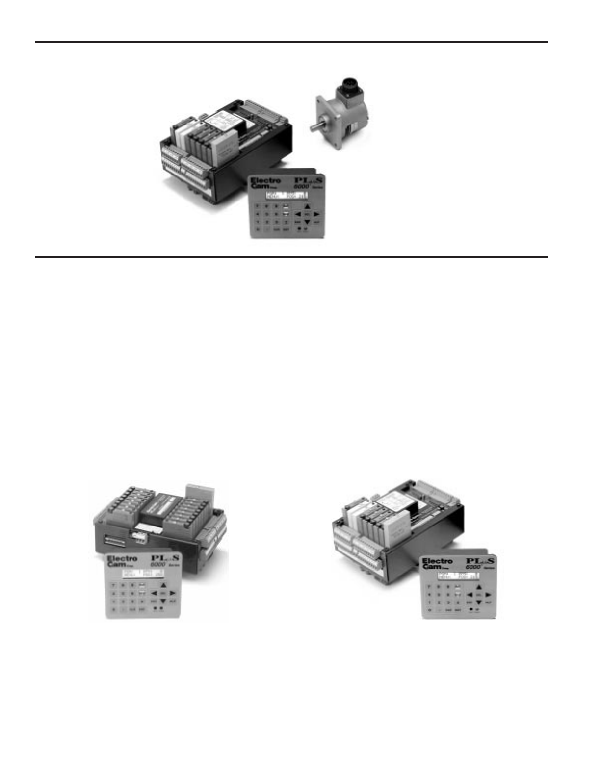
Controller & Keypad PS-6244 Series Programmable Limit Switches consist of two main components: the
controller and the keypad/display. The controller houses the microprocessor, associat-
ed circuitry, and all of the I/O circuits. This eliminates the need for external I/O racks.
A separate 1/4 DIN keypad/display provides a complete user interface from which ev-
ery aspect of the controller’s operation can be monitored and programmed. Multiple
keypads can be connected to a single controller. In addition, when interfaced to a PLC
or other computer, the controller can be used without a keypad/display. When properly
mounted with the gasket provided, the keypad/display meets NEMA 4X standards. A
clear silicon rubber boot assembly is available to provide protection for installations
where harsh washdown chemicals are used.
The PS-6244 Series is available in two models: the PS-6244-24-M17 and the PS-6244-
24-X16M09 Both are described in Figure 3.
Figure 3—PS-6244 Models
PS-6244-24-N16M09 Controller—Up to 25 OutputsPS-6244-24-M17 Controller—Up to 17 Outputs
The PS-6244-24-M17 has 17 total outputs:
• Outputs 1 through 15 can accept AC or DC output
modules for driving “real world” devices such as
solenoids, valves, or glue guns.
• Output 16 will accept an AC or DC module, or an
analog module that generates a control signal
proportional to RPM.
• Output 17 is dedicated to analog output.
The PS-6244-24-N16M09 has 25 total outputs:
• 16 transistor outputs are built into the controller.
• Outputs 17 through 23 can accept AC or DC output
modules for driving “real world” devices such as
solenoids, valves, or glue guns.
• Output 24 will accept an AC or DC module, or an
analog module that generates a control signal
proportional to RPM.
• Output 25 is dedicated to analog output.
Figure 2—PS-6244-24-N16M09 Programmable Limit Switch and Quadrature Encoder
Controller
PS-6400
Keypad/Display
Typical
Quadrature Encoder
(BEI H25D shown)
Programmable Limit Switches

1-7 Introduction
BasicTerminology
Thefollowingtermswill be used throughoutthismanualto explain PS-6244 installation,
programming and operation:
Outputs (channels) An “output,” or “output channel,” refers to an external circuit that the PS-6244 controls
based on encoder position or speed. Outputs can be one of two types:
Switching outputs turn circuits on or off.
Analog outputs generate a control signal that is proportional to RPM.
Setpoints “Setpoints” are the points within one rotation of the encoder at which an output channel
turns on or off. Setpoints can be programmed into an output channel through the key-
pad/display, or they can be downloaded from a computer or PLC through serial com-
munications. The PS-6244 can turn any given output on and off multiple times within
one rotation.
Pulses A “pulse” is the “on” period between the time an output is turned on and off. The “on”
point is the leading edge of the pulse, and the “off” point is the trailing edge. When
multiple “on” and “off” points are programmed into one output channel, the output is
said to have multiple pulses.
Programs Suppose that 15 output channels on a cartoner are programmed with setpoints to fold
andglueacertain size carton. Thesesettingscould be stored asa“program.”Then, the
15 output channels could be re-programmed with different setpoints for a different size
carton. This second set of setpoints could also be stored as a program. To change
carton sizes, an operator could simply activate the correct program, and the corre-
sponding setpoints would take effect.
Theuseof programs canprovidetremendous advantages overmechanicalcam switch-
es. Standard PS-6244’s can store up to 48 programs. The active program can be se-
lected through the keypad/display, mechanical switches, direct PLC interface, or serial
communication messages.
Inputs (hardware inputs) In addition to accepting a signal from the encoder, the PS-6244 can accept up to 16
input signals from mechanical switches, relay contacts, DC two- or three-wire sensors,
solid state DC output modules, or PLC DC outputs. The PS-6244 hardware inputs are
dedicated to specific functions involving program selection and controlling output chan-
nels based on sensor signals.

1-8 Introduction
PS-6244 Features
Programming Access Three levels of programming access are provided: Operator, Setup, and Master. Each
level can be assigned a password that must be entered to allow programming at that
level. In addition, the Operator and Master levels can be activated on an individual
keypad through hardware terminals on the back. Careful use of programming access
levels can provide key personnel the flexibility they need in programming the controller,
while protecting settings against accidental or unauthorized changes.
Speed Compensation Speed compensation advances the setpoints for an output channel as machine speed
increases. This eliminates the need to manually adjust the settings for fixed-response
deviceswhenevermachine speedsarechanged. Speedcompensationprovides greater
accuracy, higher production speeds, and reduced downtime for machine adjustment.
Motion ANDing Two speed ranges can be programmed into the controller, and output channels can be
ANDed with either speed range so that they will be disabled unless the machine speed
is within the specified range. A common use for this feature is disabling outputs to glue
valves to turn off the glue flow if the machine stops.
Input ANDing An output channel may be ANDed with one of eight input signals so that the output is
disabled unless the input signal is present.
Shift Register ANDing The PS-6244 includes a shift register that can turn output channels on or off up to 255
revolutions after a signal is applied to Input Terminal 16, Figure 7. The terminal is usu-
ally connected to a product sensor.
Analog Outputs PS-6244 controllers can drive up to two analog output modules whose output signal will
belinearly proportionalto RPM.TheanalogsignallevelatzeroRPMcanbeprogrammed,
as well as the RPM that corresponds to maximum signal. No measuring equipment is
required for initial setup, and calibration is not needed. Typical uses for the analog
output are to control glue pressure as machine speeds change, or to match speeds of
other equipment to the machine being controlled by the PS-6244.
Serial Communication Using Electro Cam Corp.’s PLuSNET software for IBM-PC compatible computers, the
PS-6244’s programs can be saved to a disk file or loaded from a disk file to the PS-
6244. The programs can be printed or edited using the computer. Individual commands
may also be sent to the PS-6244 to change settings while running.
Washdown Boot A clear silicon rubber boot can be supplied that fits over and around the keypad face.
The back of this boot provides sealing between the back of the keypad and the panel.
The boot is transparent and pliable, allowing the keypad to be viewed and operated
through it. In addition to preventing contamination from harsh chemicals, the boot also
protects the keypad from grease, oil, dirt and normal wear that could otherwise shorten
its life.

2-1 Installation & Wiring
General Mounting &Wiring
Controller The controller body mounts on a DIN rail as shown in Figure 4.
Keypad/Display Mount the keypad/display to a panel using the four studs on the back of the keyboard.
Enclosures are available from Electro Cam if an appropriate mounting location does
not exist.
DIP Switches For convenience, set the DIP switches on the side of the controller and keypad to
their proper positions before mounting the units in a panel. See page 2-13 for DIP
switch information.
Environment 1. Allow space at both sides and the top of controller for terminal blocks to be un-
plugged.
2. Ambient temperature range is +32°to +130°F (0°to +55°C)
3. Locate the controller and keypad away from devices that generate electrical noise,
such as contactors and drives.
4. Use the keypad/display gasket provided to prevent contaminants from getting into
the cabinet.
Terminal Blocks All terminal blocks can be unplugged from the controller. Each block is keyed so it
cannot be plugged into the wrong socket. All terminals are labelled on each block.
Wiring Guidelines Follow normal wiring practices associated with the installation of electronic controls.
Some guidelines are:
1. Route input and output wiring away from high voltage, motor drive, and other high
level control signals.
2. Use shielded cables for encoder, input, transistor output, and communication cir-
cuits. Also shield module output circuits that are driving low current electronic input
circuits.
3. Ground shielded cables at the PS-6244 end only (except for encoder cable). Use
any of the screws on the controller back for grounding.
4. Use appropriate suppression devices where module outputs are directly driving in-
ductive loads.
Power Supply Wiring Connect a 20 to 30 VDC power supply to TB8 (Fig. 5 or 6). Reversing the polarity will
blow the 1-1/4 amp power fuse. The controller will not be damaged, but you must cor-
rect the polarity and replace the fuse before the controller will operate.
Toinsure electricalnoise immunity,connect agood electricalground tothe ground
terminal on the power supply terminal block.
Module Mounting A phillips head screw holds each module in place. Individual modules can be removed
and installed without affecting the other modules on the unit
However, disconnect power to the controller before changing modules.
CAUTION
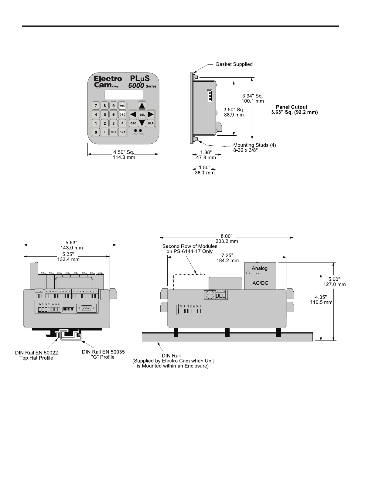
2-2 Installation & Wiring
Figure 4—Mounting Dimensions
Mounting Dimensions
PGM:1 RPM:1500
MENU< POS: 180
2-3 Installation & Wiring
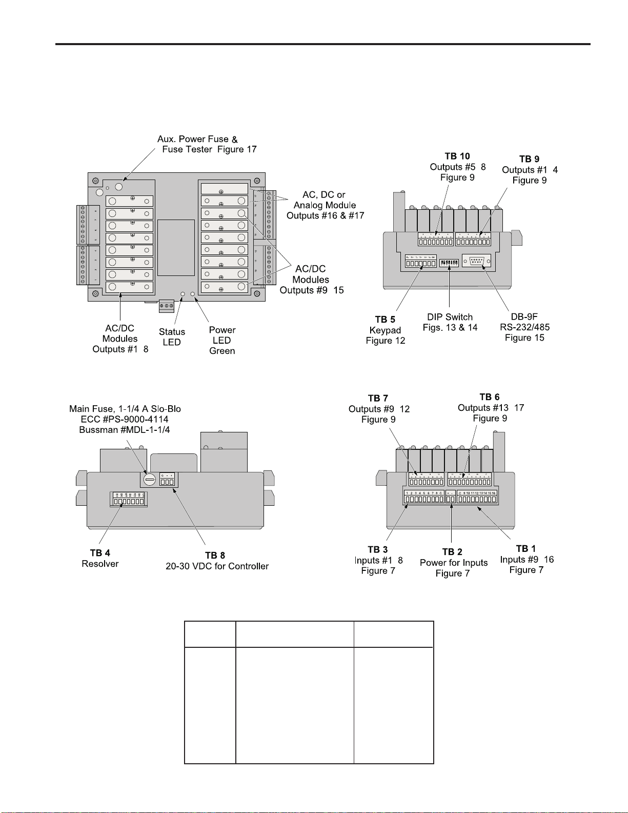
Terminals & Components—PS-6244-24-M17
Figure 5—PS-6244-24-M17 Terminals & Components
Terminal Block Details
1Keyed to prevent accidental insertion into wrong sockets.
Terminal
Block Function ECC Part #1
TB 1 Inputs #9–16 PS-9006-0024
TB 2 Auxiliary power output PS-9006-0018
TB 3 Inputs #1–8 PS-9006-0023
TB 4 Encoder connector PS-9006-0032
TB 5 Keypad connector PS-9006-0029
TB 6 Module outputs #13-17 PS-9006-0031
TB 7 Module outputs #9-12 PS-9006-0030
TB 8 Power for controller PS-9006-0026
TB 9 Module outputs #1-4 PS-9006-0033
TB 10 Module outputs #5-8 PS-9006-0034
Top View
Front View Right Side View
Left Side View
-
-
-
-
-
-
-
-
Yellow

2-4 Installation & Wiring
Terminals & Components—PS-6244-24-X16M09
Figure 6—PS-6244-24-X16M09 Terminals & Components
Top View
Terminal Block Details
1Keyed to prevent accidental insertion into wrong sockets.
Terminal
Block Function ECC Part #1
TB 1 Inputs #9–16 PS-9006-0024
TB 2 Auxiliary power output PS-9006-0018
TB 3 Inputs #1–8 PS-9006-0023
TB 4 Encoder connector PS-9006-0032
TB 5 Keypad connector PS-9006-0029
TB 6 Module outputs #21–25 PS-9006-0028
TB 7 Module outputs #17–20 PS-9006-0027
TB 8 Power for controller PS-9006-0026
TB 9 Transistor outputs #1–8, sinking PS-9006-0019
Transistor outputs #1–8, sourcing PS-9006-0021
TB 10 Transistor outputs #9–16, sinking PS-9006-0020
Transistor outputs #9–16, sourcing PS-9006-0022
TB 11 Power for transistor outputs PS-9006-0017
Left Side View
Right Side View
Front View
Yellow
-
-
-
--
-
-
-

2-5 Installation & Wiring
Controller InputWiring
Input Terminals Hardware inputs can be used to select a program of setpoints, disable keypads, accept
sensor signals, or clear the shift register. The 16 inputs on the PS-6244 are arranged
on two terminal strips, TB 1 and TB 3, as shown in Figure 7. Each input is optically
isolated and can be powered from an external DC power source or the Auxiliary Power
terminals located on TB 2.
Sinking or Sourcing Each terminal strip TB 1 and TB 3 can be wired to accept sinking or sourcing input
signals, but all eight inputs on that strip will require the same type of signal. Many types
of hardware can drive these inputs, including mechanical switches, relay contacts, DC
3-wire sensors, solid state DC output modules, and PLC DC outputs. 2-wire DC sen-
sors can also be used, but may require a load resistor in parallel with the input. Typical
wiring diagrams are shown in Figure 7.
Input Functions Following are the input terminals and their corresponding functions:
Channel Enable (1-8)
These terminals accept signals from sensors or from PLC’s. Each output channel on
the 6244 can be ANDed with any one of these inputs so that the output is enabled only
when a signal is present on the input terminal.
Program Select (9-13)
The on/off status of these terminals selects which program of setpoints is controlling
the outputs. Binary, BCD, or Gray Code formats can drive these terminals as shown in
Figure 8. Although standard controllers can store up to 48 programs, not all of these
programs can be selected through the Program Select terminals.
When all program select inputs are off, the “Default” program will become active as
programmed through DEFAULT PROGRAM function.
Shift Register Clear (14)
A signal on this terminal will completely clear the shift register for all output channels.
Keypad Disable (15)
When energized, this terminal disables any keypads connected to the controller. If the
controller will be used without any keypads, jumper this terminal so that it is always
energized.
Shift Register Input (16)
The leading edge of a signal on this terminal sets a bit in the shift register. See SHIFT
REGISTER ANDING for details.

2-6 Installation & Wiring
Controller InputWiring (cont’d)
Figure 7—Controller Input Wiring (See Figures 5 & 6 for Terminal Block Locations)
Sourcing Devices
(+VDC is being switched) Sinking Devices
(DC common is being switched)
Input Wiring Guidelines
• Voltage from TB 2 will be the same as the voltage supplied to the controller.
• Each input powered from TB 2 will draw 11 mA at 24 VDC. TB 2 is fused at 1/4 amp.
• Inputs will operate with voltages from 10 to 30 VDC.
• An external power supply can be used instead of TB 2 to power inputs.
• A combination of mechanical and solid state devices can be used.
• TB 1 can be wired for sourcing while TB 3 is wired for sinking, and vice versa.
Term. Function
1-8 ChannelEnable
9-13 Program Select
14 Shift Register Clear
15 Keypad Disable
16 Shift Register Input
-
-
-
-

2-7 Installation & Wiring
Controller InputWiring (cont’d)
Figure 8—Program Select Terminals for Various Formats
BCD Program Select Table
Input
Term: 13 12 11 10 9
Value: 10 8 4 2 1
PGM
Default 0 0 0 0 0
100001
200010
300011
400100
500101
600110
700111
801000
901001
Input
Term: 13 12 11 10 9
Value: 10 8 4 2 1
PGM
10 10000
11 10001
12 10010
13 1 0 0 1 1
14 10100
15 10101
16 10110
17 10111
18 11000
19 11001
UNITS10's 10'sUNITS
The BCD format allows standard 1- or 2-digit BCD switches
to operate the program select inputs. PLC’s can also
output values in BCD. The program number selected can
be calculated by adding up the values associated with
each of the input terminals that are on. For example, if
Input Terminals 9, 11 and 13 are on, Program 15 would be
active (10 + 4 + 1).
Please Note:
• Although the PS-6244 can store up to 48 programs, only
Programs 1 through 19 can be selected using BCD input.
A value larger than 19 will select Program 19.
• Only one of the normal four BCD digits for 10’s is used.
• 9 is the largest valid value for the units digit. A units
digit combination larger than 9 will set the units digit to 9.
Binary Program Select Table
The binary format is convenient for PLC program select
output signals. The program number selected can be
calculated by adding up the values associated with each
of the input terminals that are on. For example, if input
terminals 9, 11 and 13 are on, program number 21 would
be active (16 + 4 + 1).
Please Note:
• Although the PS-6244 can store up to 48 programs, only
Programs 1 through 31 can be selected using binary
input. A value larger than 31 will select Program 31.
Input
Term: 13 12 11 10 9
Value: 16 8 4 2 1
PGM
Default 0 0 0 0 0
1 00001
2 00010
3 00011
4 00100
5 00101
6 00110
7 00111
8 01000
9 01001
10 01010
11 01011
12 01100
13 0 1 1 0 1
14 01110
15 01111
Input
Term: 13 12 11 10 9
Value: 16 8 4 2 1
PGM
16 1 0 0 0 0
17 10001
18 10010
19 10011
20 10100
21 10101
22 10110
23 10111
24 11000
25 11001
26 11010
27 11011
28 11100
29 1 1 1 0 1
30 11110
31 11111
Gray Code Select Table
Electro Cam 8-position Gray Code selector switches are
available as accessories for PLuS controls.
Please Note:
• Although the PS-6244 can store up to 48 programs, only
Programs 1 through 31 can be selected using gray code
input. A value larger than 31 will select Program 31.
Input MSB LSB
Term: 13 12 11 10 9
PGM
Default 0 0 0 0 0
100001
200011
300010
400110
500111
600101
700100
801100
901101
10 0 1 1 1 1
11 0 1 1 1 0
12 0 1 0 1 0
13 0 1 0 1 1
14 0 1 0 0 1
15 0 1 0 0 0
Input MSB LSB
Term: 13 12 11 10 9
PGM
16 11000
17 11001
18 11011
19 11010
20 11110
21 11111
22 11101
23 11100
24 10100
25 10101
26 10111
27 10110
28 10010
29 10011
30 10001
31 10000

2-8 Installation & Wiring
Output Wiring
Output Types The outputs available depend on the PS-6244 Model:
Output Model Model
Type 6244-24-M17 6244-24-X16M09
Transistor None Outputs 1-16
AC/DC/RR Modules Only Outputs 1-15 Outputs 17-23
AC/DC/RR or Analog Modules Output 16 Output 24
Analog Modules Only Output 17 Output 25
The load device to be driven must match the output type.
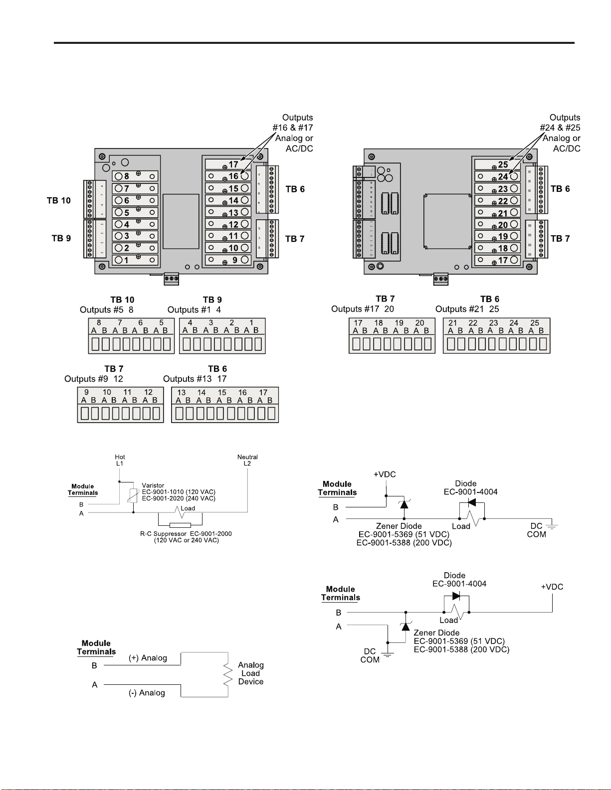
Power Output Modules Outputmodulescan directly switchinductiveloadsand resistive loadsthatrequire more
current or voltage than the transistor outputs can supply. The modules do not supply
the power for the load; they simply switch it. Each output module has two dedicated
terminals and therefore does not share any common signal with the other modules.
This allows AC and DC modules to be mixed on the same control. DC modules can be
wired to sink or source as shown in Figure 9.
Analog Output Modules Analog output modules generate signals that are proportional to the encoder RPM.
They can be used only in the output positions shown above. Either a 0-10 Vdc or 4-20
mA analog module can be used in either module position. ANALOG QTY must be
programmed for the number of analog modules installed. An external power supply is
not needed because the analog modules get the power they source from the controller.
The analog output signal is completely isolated.
Transistor Outputs PS-6244-25 models include 16 transistor outputs to drive the electronic input circuits of
other control devices. The outputs are limited to 30 Vdc, 50 mA each and should not be
used to control inductive devices such as solenoids, solenoid valves or relays.
Thecontrolcanbeordered with either sinkingorsourcingtransistoroutputs. Both types
require a 10-30 VDC power supply connected to TB 11 to drive the transistor output
circuitry. The transistor output fuse will blow if the power supply polarity is incorrect, but
the circuitry will not be damaged. See Figs. 17 & 18 for fuse and transistor chip replace-
ment.
Sinking transistor outputs (N16 controls, Figure 10) conduct to the negative termi-
nal of TB 11. Therefore the common for TB 11 and the load must be electrically the
same. This may require connecting commons together if the power supplied to TB 11 is
not also the load power supply. Electronic counters/ratemeters often fall into this cat-
egory. The power supply that powers the load does not have to be the same voltage as
the transistor power supplied to TB 11.
Sourcing transistor outputs (P16 controls, Figure 11) conduct to the positive power
terminal of TB 11. The load is therefore powered from the same supply that is providing
the transistor power.
2-9 Installation & Wiring
OutputWiring (cont’d)
• Analog output modules source the analog signal.
• No external supply is required.
• Analog output signals are isolated.
DC Output
AC Output
Sourcing
• WhenotherswitchingdevicesareinseriesorparallelwiththeACoutput
module, connect a varistor (MOV) across the terminals to prevent
module damage from inductive voltage spikes.
• Output modules act like switches; they do not supply power to loads.
Analog Output
• Suppress spikes in inductive DC loads with one of the following
methods:
Connect a zener diode across the terminals. Turn off time will not be
significantly affected. Voltage rating of diode must be greater than the
normal circuit voltage. 50 VDC Zener, #EC-9001-5369; 200 VDC
Zener, #EC-9001-5388.
Connect a reverse-biased diode across the load. This will increase the
turn off time of the load. #EC-9001-4004.
Sinking
Figure 9—Wiring for Output Modules
PS-6244-24-X16M09
PS-6244-24-M17
-
---
-
-
-
-
2-10 Installation & Wiring
Output Wiring (cont’d)
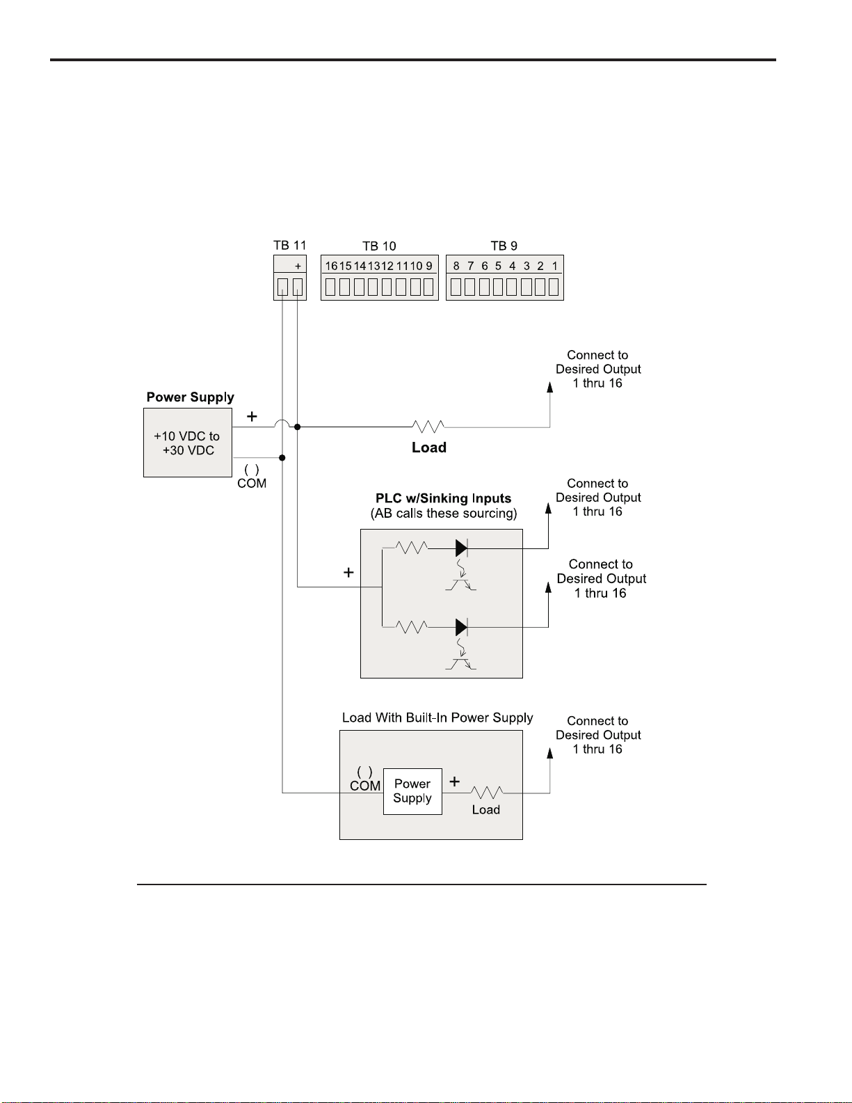
Figure 10—Wiring for Sinking Transistor Outputs (See Figure 6 for Terminal Block Locations)
Model PS-6244-24-N16M09
Please Note:
• Outputs are rated at 30 VDC, 50 mA.
• Transistor outputs should not be used to switch inductive devices such as solenoids or
relays.
• Sinking outputs conduct to the negative terminal of TB 11 when “on.”
• The power supply shown in “Load with Built-In Power Supply” does not have to be the same
voltage as the power supply connected to TB 11.
-
-
-

2-11 Installation & Wiring
OutputWiring (cont’d)
Figure 11—Wiring for Sourcing Transistor Outputs (See Figure 6 for Terminal Block Locations)
Model PS-6244-24-P16M09
Please Note:
• Outputs are rated at 30 VDC, 50 mA.
• Transistor outputs should not be used to switch inductive devices such as solenoids or relays.
• Sourcing outputs conduct to the positive terminal of TB 11 when “on.”
-
-
-

2-12 Installation & Wiring
Keypad Wiring
Number of Keypads One or two keypads may be connected to a PS-6244 controller as shown in Figure 12.
See Figure 14 for possible system configurations.
Programming Enable The wiring connector on the back of each keypad includes terminals to select Operator
or Master level programming for that keypad. These terminals can be temporarily
jumpered during set-up to allow entry of programming access codes, or they can be
switched with a variety of devices including mechanical switches, relay contacts, and
PLC DC outputs. See ENABLE CODES in the programming section for details on pro-
gramming access.
If a solid state device will be activating the Programming Enable terminals, that device
will determine whether sourcing or sinking wiring should be used. For mechanical de-
vices such as jumpers or key switches, either sourcing or sinking wiring may be used.
Figure 12—Keypad Wiring
Programming Enable, Sourcing Programming Enable, Sinking
--
-
Keypad Connector
on Controller Keypad
Terminal Block Keypad
Terminal Block
Bk Wh Bk Gn Rd Bk Bk Wh Bk Gn
Rd Bk Bk Wh Bk Gn
Rd Bk
--
This manual suits for next models
3
Table of contents
Other Electro Cam Switch manuals


Popular Switch manuals by other brands

Spirax Sarco
Spirax Sarco Beta P Assembly, installation, adjustment

Extron electronics
Extron electronics VSW 2VGA A user guide

Cisco
Cisco Catalyst 2960-XR Reference

Open House
Open House H628 ChannelPlus installation guide

Master View
Master View CS-1804 user manual

bluelab
bluelab Powerpod Care and use guide


