Indu-Sol PROmesh P9+ User manual


Indu-Sol GmbH
Blumenstraße 3
D-042626 Schmölln
Phone: +49 (0)34491 / 580 0
Fax: +49 (0)34491 / 580-499
Email: info@indu-sol.com
Web: https://www.indu-sol.com
Our technical support team is available at +49 (0)34491 / 58 18 14, weekdays between 7:30 –16:30 (CET).
You can also email us at: support@indu-sol.com
Is your plant standing still? You can reach our emergency service around the clock at:
+49 (0)34491 / 580 0.

Revision overview
PROmesh P9+–User Manual 3
Revision overview
© Copyright 2022 Indu-Sol GmbH
We reserve the right to amend this document without notice. We continuously work on further developing
our products. We reserve the right to make changes to the scope of supply in terms of form, features, and
technology. No claims can be derived from the specifications, figures, or descriptions in this documentation.
Any kind of reproduction, subsequent editing, or translation of this document, as well as excerpts from it,
requires the written consent of Indu-Sol GmbH. All rights under copyright law are expressly reserved for
Indu-Sol GmbH.
W A R N I N G
Commissioning and operation of this device must only be performed by qualified personnel. Qualified
personnel within the meaning of the safety notices in this manual are persons authorised to commission,
ground, and mark devices, systems, and circuits in accordance with safety engineering standards.
Improper use or configuration of the PROmesh P9+ in the network may cause severe physical injury as
well as property and material damage, also due to uncontrolled machine movements.
Date
Revision
Change(s)
30/06/2022
0
First version
16/08/2022
1
Switch Technology
30/11/2022
2
VLAN Menü

Table of contents
PROmesh P9+–User Manual 4
Table of contents
Revision overview 3
Table of contents 4
1General information 6
1.1 Overview of the PROmesh P9+ –function scope 6
1.2 Scope of supply 7
1.3 Safety notices 7
2Connections and status indicators on the device 8
2.1 Device connections 8
2.2 Installation 9
2.3 Mounting 9
2.4 Connection of power supply and error relay 10
2.5 LED displays 12
2.6 Reset button 12
2.7 Network integration & commissioning 13
Data ports 13
Media selection & connection 13
Wiring 13
2.8 Network topologies & redundancy 14
Network topologies 14
Ring structure 14
3Web application 16
3.1 Preparations 16
3.2 System login 17
3.3 Web interface 17
3.4 Start 18
3.5 System information 20
3.6 Diagnosis 20
Line diagnostics 20
Leakage current 22
Network statistics 22
Neighbourhood detection (LLDP) 24
Port mirroring 24
Alarm trigger 25
Messages 27
3.7 PROFINET 28

Table of contents
PROmesh P9+–User Manual 5
3.8 Switching 28
Port configuration 28
Quality of service 30
VLAN 31
Bandwidth control 32
Link aggregation 33
3.9 Redundancy 34
MRP 34
RSTP 35
MSTP 38
3.10 System configuration 39
Device information 39
IP configuration 40
Password 41
Time setting 41
SNMP 42
Access time 43
Backup 44
Recovery 44
Firmware update 44
Factory settings 46
Reboot 46
3.11 Support 46
3.12 Troubleshooting advice 46
4Technical specifications 48

General information
PROmesh P9+–User Manual 6
1 General information
Please read this document thoroughly from start to finish before you begin installing the device and putting
the device into operation.
1.1 Overview of the PROmesh P9+ –function scope
The PROmesh P9+ is an industrial Ethernet switch with management and PROFINET functions that can be
configured easily and conveniently via a web application. It supports the effective setup of all network
topologies, such as bus, star, and ring structure in your plant, with its comprehensive functions with Store &
Forward technology.
Features:
Web application for configuration
Anti-reverse supply 12-48V DC, redundant operation possible
Line diagnostics
Leakage current monitoring
Port statistics (network load in ms, errors, discards)
Alarm management
9 x 10/100/1000 Mbit/s RJ45
Switch technology: Store & Forward
MAC address table: 16K (16384 addresses)
PROFINET Conformance Class B
PROFINET Netload Class III
Quality of Service (QoS) with eight priority queues
Prioritisation by class of service (COS), type of service (TOS), or port priority
Limitation of incoming and outgoing packets
Port mirroring (Rx/Rx and Tx packets)
Port-based VLAN with 4096 possible VLAN IDs
Simple Network Time Protocol (SNTP) client and NTP server
Simple Mail Transfer Protocol (SMTP)
Internet Group Management Protocol - Snooping (IGMP Snooping)
Dynamic Host Configuration Protocol (DHCP) client function
Simple Network Management Protocol (SNMP), v1, v2c, v3
Update, save, and backup the system configuration via web interface, TFTP, and memory card

General information
PROmesh P9+–User Manual 7
1.2 Scope of supply
The scope of supply comprises the following individual parts:
PROmesh P9+
7-pin pluggable terminal block, 2.5 mm² (power supply and alarm contact)
User quick start guide (hardcopy)
SD card, for backup and update
Check that the content of your delivery is complete before commissioning. In case of questions, contact our
technical support team immediately before commissioning.
Insert the external memory card into the corresponding slot on the back of the unit before using
the device for the first time (see Figure 1).
1.3 Safety notices
Check that it is in perfect condition externally before commissioning of the device. If any damage
is suspected, return the PROmesh P9+ to your supplier immediately and do not operate the
device. Our technical support team will be happy to answer any questions you may have.
The PROmesh P9+ was developed for use in PROFINET applications in accordance with
conformance class B. Also note the selection of the data lines used in accordance with the
standard to fully support the PROFINET standards.
Always observe the technical specification of the device to ensure safe and optimum use. The
device is designed for IP30 protected environments. Take appropriate measures in case of
deviating operating environment to ensure proper operation of the device.
Do not open the housing under any circumstances. No parts that require servicing have been
installed. Unauthorised opening of the housing will void any warranty claims.

Connections and status indicators on the device
PROmesh P9+–User Manual 8
2 Connections and status indicators on the device
2.1 Device connections
X1 data ports
9x RJ45
Status LEDs
Figure 1: Device connections
X2 Power supply
and alarm contact
FE connection
Potential-free
switching contact
24 V
0 V
Reset
SD card holder

Connections and status indicators on the device
PROmesh P9+–User Manual 9
2.2 Installation
The PROmesh P9+ is designed for individual use in control cabinets of various types and can be mounted
on a standard 35 mm DIN top-hat rail.
Only use the existing top-hat rail fastening for mounting the device or, if necessary, purchase appropriate
spare parts to ensure sufficient electrical contact and the mechanical load capacity of the device.
2.3 Mounting
The PROmesh P9+ is mounted vertically in the control cabinet on a 35 mm DIN top-hat rail in accordance
with DIN EN 60715.
Figure 2: Side view with connection terminal on the right
The following distances to other assemblies must be observed for correct mounting:
To the left and right: 20 mm
Up and down: 50 mm
Assembly and disassembly of the device are displayed in Figure 3.

Connections and status indicators on the device
PROmesh P9+–User Manual 10
Figure 3: Mounting and dismounting on the top-hat rail
Do not mount the PROmesh P9+ switches directly adjacent to any devices that generate strong
electromagnetic interference fields, such as transformers, contactors, frequency converters, etc.
Do not mount the PROmesh P9+ switches directly adjacent to any heat-generating devices and
protect the switch from direct sunlight to avoid unwanted heating. Protect the PROmesh P9+ from
any additional heat radiation and observe the permitted storage and operating temperature range.
2.4 Connection of power supply and error relay
Operate your PROmesh P9+ with a nominal voltage of DC 12 V to 48 V. Connect the redundant power
supply VDC1 and VDC2 to the correspondingly marked connection terminals of the supplied 7-pin terminal
block adapter (VDC1, GND as well as VDC2, GND) to ensure your system availability. The power supply
shall comply with UL60950-1/UL62368-1, Class 2 (NEC), limited energy source (UL61010-1).
The 7-pin 2.5 mm² connector terminal block on the top of the device is assigned as follows:
The listed labels are also included on the connector terminal block supplied.
Figure 4:Connector terminal block assignment
VDC1
VDC2
Relay

Connections and status indicators on the device
PROmesh P9+–User Manual 11
There is a potential-free error relay contact (NC contact) at the OUT terminals inside the unit. The relay
serves as an alarm receiver. It can be linked to various alarm triggers in the software. The relay contact
then opens, for example, in case of a power outage or a change in the status of the port depending on the
configuration.

Connections and status indicators on the device
PROmesh P9+–User Manual 12
2.5 LED displays
There are four diagnostic LEDs on the front panel of the switch.
Each of the 9 data ports also has a status LED.
The LEDs display the most important diagnostic information about the device and connection status of the
PROmesh P9+ in your PROFINET network (see Table 1).
LED
Status
Meaning
VDC1
Green
Voltage at connection sufficient
Off
Voltage at connection insufficient
VDC2
Green
Voltage at connection sufficient
Off
Voltage at connection insufficient
Status
Green
Active PROFINET connection to the controller
Yellow
No PROFINET connection to the controller
Error
Red
Configured alarm active
Off
No configured alarm active
LED ports 1-9
(green)
Off
No link
Flashing
Link + data exchange (flashing speed reflects link speed)
On
Link
Table 1: LED functions
2.6 Reset button
The reset button can be used if the PROmesh P9+ experiences any unexpected abnormalities that render
it inaccessible. It can either restart the PROmesh P9+ or reset to its factory settings. This requires the
following procedure:
Restarting the device: Push the reset button for 1 second
Reset to factory settings: Push the reset button until all LEDs go out (approx. 10s)

Connections and status indicators on the device
PROmesh P9+–User Manual 13
2.7 Network integration & commissioning
Data ports
The PROmesh P9+ is equipped with 9 data ports that allow data transmission at up to 1.0 Gbit/s in
compliance with PROFINET standard 2.4. The actual data rate is negotiated by the device using auto-
negotiation.
Media selection & connection
The PROmesh P9+ has nine data ports for connecting RJ-45 copper cables.
Observe the applicable standards and fixed connections in the connector application when designing,
selecting, assigning, and assembling your data cable in order to ensure the longest possible cable length
and cascading of network segments in accordance with your media type (copper, optical fibre, etc.).
Wiring
Connect your PROmesh P9+ via the existing RJ-45 data ports using twisted pair cables of
category 5 (Cat 5) or higher with a maximum cable length of up to 100 m. We recommend the
PROFINET RJ45 connectors from Indu-Sol to improve the shielding.
Connections and status indicators on the device
PROmesh P9+–User Manual 14
2.8 Network topologies & redundancy
The devices of the PROmesh product family can be used in redundant networks, such as meshed networks
or rings, via different protocols in addition to being used in star-shaped switched Ethernet networks.
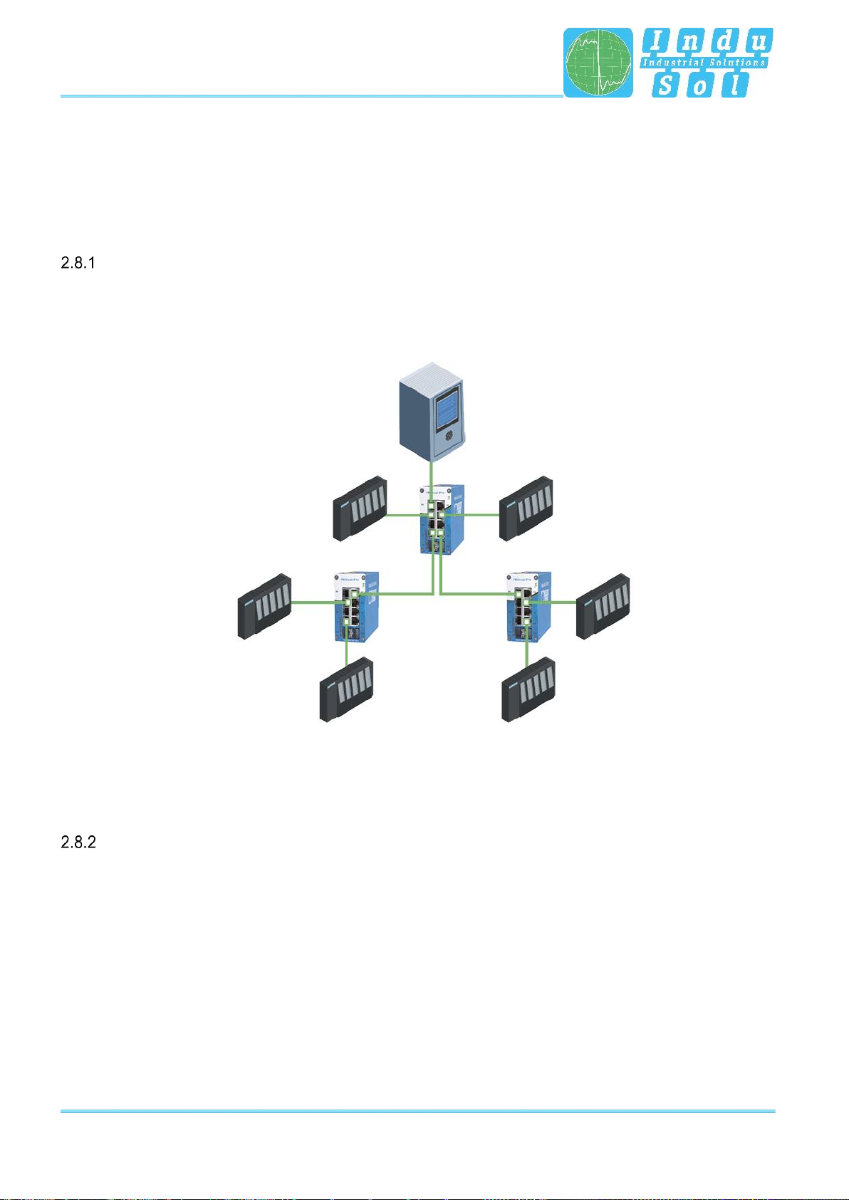
Network topologies
Classical Ethernet star structures (see Figure 5) can be linked to the PROmesh P9+ switches without
additional configuration. The devices are ready for use immediately.
Figure 5: PROmesh P9+ in a star network
Ring structure
The PROmesh P9+ supports the IEC 62439 standard, thereby enabling deterministic reconfiguration of
information forwarding in simple redundancy (ring topologies, see Figure 6). This enables reconfiguration
times of up to 200 ms, depending on the size of your system.

Connections and status indicators on the device
PROmesh P9+–User Manual 15
Figure 6: PROmesh P9+ in a ring-shaped network

Web application
PROmesh P9+–User Manual 16
3 Web application
The PROmesh P9+ switches are equipped with a modern web interface that may be configured comfortably
from any web browser.
3.1 Preparations
Install the PROmesh P9+ switch on the network before using web management and ensure that the PC
designated to configure the switches can access the switch through the web browser. The PROmesh P9+
and the client PC to be connected must be in the same IP address range and IP subnet. You must assign
an PROmesh P9+ IP address at first use for this.
The following IP address, subnet mask, administrator username, and administrator password are set when
the device is shipped from the factory:
IP address: 0.0.0.0
Subnet mask: 0.0.0.0
Gateway: 0.0.0.0
Username: admin
Password: admin
Make sure to change the factory-set password when logging in for the first time. You are
responsible for documenting this password and protecting it from unauthorised
access.
You can easily set your intended user addresses with the Indu-Sol ServiceTool. This is part of the scope
of delivery or can be downloaded for free via the following link:
https://sdx.indu-sol.com/s/CtYtsHNW73Z3KCa
Our software is updated regularly. Please ensure that you have the latest version.
Establish a network connection from your computer to a port of the switch and scan the system with the
search setting PROFINET device after installing and opening the software. You can then make the
appropriate entries in the input mask and save them.
The corresponding address settings are then made automatically this way if you include the switch in a
PROFINET system in the hardware configuration of the controller.
A user access with lower authorizations and adapted menu navigation is available as an alternative to the
administrator access. The user has no access to the Switching, PROFINET and redundancy functions or
their sub-items. The submenus for system configuration are also restricted. The access data for this are:
Username: user
Password: user

Web application
PROmesh P9+–User Manual 17
3.2 System login
1. Launch a web browser on your computer.
2. Enter the IP address of the PROmesh P9+ switch you are using into the address line of the web browser
and confirm your entry with the Enter key.
3. The login mask of the device now appears on the screen.
Figure 7: Login mask
4. Select the desired menu language (DE / EN). You can change this at any time, in any menu of the web
interface.
5. Then enter the username and password.
6. Pressing the Enter key or clicking Login will take you to the switch web interface.
3.3 Web interface
The following symbols are used in the web interface for a simple status display of the individual ports:
No error: The communication works without any errors.
Warning: At least one communication fault (discards, error) has occurred on
the corresponding port, which has not yet led to a failure. The cause of these
events should be located and corrected.
Error: A critical fault has occurred on the corresponding port, resulting in a
communication interruption. Urgent action is needed to correct the disruption.

Web application
PROmesh P9+–User Manual 18
There is no communication at the respective port. Either no device is
connected (potentially also at line interruption) or no telegram traffic can be
detected (serious fault in the network) or the devices no longer communicate.
3.4 Start
Successful login will lead to the main overview with the information bar, where the device name, the
installation location, and the IP address are displayed. The current user is displayed under the logout button
at the right end of the bar. You can log out by pushing the button. The help button displays notes and
explanations for the individual pages.
The port statistics provide an overall view of the state of the existing ports since the switch was started or
reset (history) and within the last minute (current). You can choose between two views. In the Overview
view:
Current partners
Transmission speed
Diagnostic messages
are displayed. In the Details view, the parameters of the overview and:
Mains load per s
Discards
Errors
Line quality value
are displayed.
The number of messages that have occurred is displayed in the message window. Clicking on the alarm
bell will automatically call up the entries in the message list. The messages as well as the counter status of
the ports can be deleted with the corresponding buttons.
The leakage current overview shows the current value between the RJ45 ports and the device’s top-hat
rail. It is possible to switch between the display of the peak value (peak) and the effective value (RMS) or
this. This information makes interference currents visible at an early stage, which can lead to direct
communication disturbances.
The top-hat rail must have been grounded properly in order to measure the leakage current
correctly.
Selection in the menu bar allows you to call up the individual pages and make settings there. The displayed
menu items are subdivided into further subitems.

Web application
PROmesh P9+–User Manual 19
Figure 8: Start
Leakage
current
Port
statistics
Message
window

Web application
PROmesh P9+–User Manual 20
3.5 System information
An overview of the enabled or disabled protocols and functions is displayed under this menu item in addition
to the device information. You can switch directly to the corresponding protocols and functions in order to
make settings there by selecting the respective Edit button.
Figure 9: Status and diagnosis
3.6 Diagnosis
The diagnosis page provides an overview of the status of configured alarm triggers (alarm trigger configured
or not) for the individual diagnostic data acquired by the PROmesh P9+. The status for topology
determination and port mirroring is also displayed.
Line diagnostics
Line diagnosis is available for ports 1 –9. The quality of the connected connections is checked cyclically
(every second). The line quality can lie between the values 100 and 0%. In this context, 0% corresponds
to a defective cable, i.e., no data exchange is possible.
Other manuals for PROmesh P9+
1
Table of contents
Other Indu-Sol Switch manuals

Indu-Sol
Indu-Sol PROmesh P9 User manual

Indu-Sol
Indu-Sol PROmesh P20 User manual

Indu-Sol
Indu-Sol PROmesh B28-R Setup guide

Indu-Sol
Indu-Sol PROmesh U16 Setup guide

Indu-Sol
Indu-Sol PROmesh U3 User manual

Indu-Sol
Indu-Sol PROmesh B16 Setup guide

Indu-Sol
Indu-Sol PROmesh P9+ Setup guide

Indu-Sol
Indu-Sol PROmesh P10X User manual

Indu-Sol
Indu-Sol PROmesh B8 Setup guide

Indu-Sol
Indu-Sol PROmesh P12 PoE User manual


