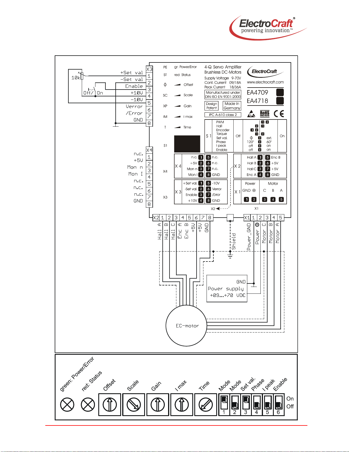
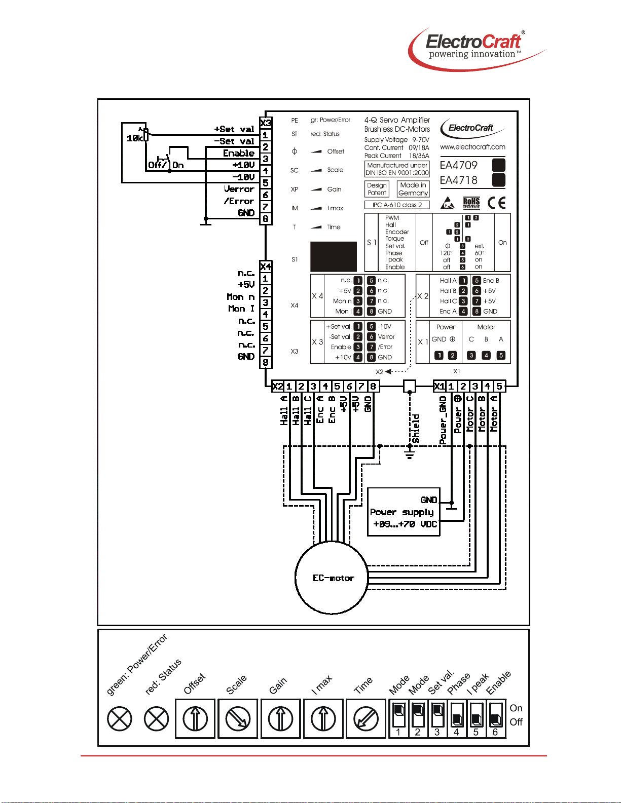
Electro-Craft EA4709 User manual

User Manual EA4709 / EA4718
ElectroCraft®E-Mail: info@electrocraft.com www.electrocraft.com May 2009
1
For Brushless-Commutated DC Motors up to 1260 W
EA4709 / EA4718
•Servo amplifier in a small size, rugged aluminium housing in (bookshelf form)
•Different methods of mounting for fast installation
•Tool free connections for power terminations
•Inputs and outputs via RJ45-CAT5 plug
•Operation mode with simple DIP switch setting
•User adjustable current limit and ramp function
•Wide range supply voltage between +9 and +70 VDC for different kinds of DC-power
supplies
•Protected against overtemperature and over-current
•MOSFet-technology, efficiency 97%
•Continuous current up to 9 / 18 A (model dependent)
Basic drive description: The EA4709 / EA4718 servo amplifiers are designed to drive DC
brushless type motors. They require a single DC power supply for operation. The drives
are to be used with a single motor. They have the functionality to operate as an
independent speed control or high performance servo. The drives are protected against
short circuits, under voltage, over temperature, and over current. It has multiple modes of
operation and serves as a reliable choice for your motion control needs.
4–Q PWM Servo – 09 / 18 A

User Manual EA4709 / EA4718
ElectroCraft®E-Mail: info@electrocraft.com www.electrocraft.com May 2009
2
Table of Contents
1. Safety & Installation .........................................................................3
2. Specifications:..................................................................................4
3. Drive Overview..................................................................................7
4. Wiring...............................................................................................10
5. Explanation of Terminals, Dip Switches, & Potentiometers.......21
6. Glossary .......................................................................................... 25
7. Description of Inputs and Outputs................................................31
8. Basic Troubleshooting...................................................................35
9. Accessories & Options .................................................................. 37
10. Warranties & Disclaimers .............................................................. 38
11. Dimensions .....................................................................................39
12. Mounting Din rail adapter ..............................................................39
Used Symbols
Indicates a warning or caution concerning operations that may lead to
death or injury to persons, or damage to property if not performed correctly.
In order to use the drive safely, always pay attention to these warnings.
Indicates a clarification of an operation, or contains additional explanations,
or operational requirements for a procedure. Reading these notes is much
recommended.

User Manual EA4709 / EA4718
ElectroCraft®E-Mail: info@electrocraft.com www.electrocraft.com May 2009
3
1. Safety & Installation
The EA4709 / EA4718 requires installation by qualified personal which must
pay attention to significant safety and other regulatory standards. They should
be thoroughly familiar with the entire system before beginning installation.
Before final operation of machine be sure to test hookup with motor but
disconnected from the load. Improper wiring could cause a “motor run away”
condition, and cause serious injury or damage to the machine and personal.
Before starting installation of the EA4709 / EA4718, be sure that main power
is disconnected. After powering the drive it should not be touched by hand or
risk shock.
Take care that in case of regeneration or in brake operation the energy
recovery must be buffered by the power supply and / or a braking module.
Ensure with electronically stabilized power supplies that protection circuit isn’t
react.
Don’t switch off the power supply while the motor is turning, in this case the
drive could be destroyed by regeneration.
We recommend connecting a capacitor of 1000 µF per each ampere output
current close to power input, in parallel.
Do not repair or open drives enclosure. Result would result in personal injury
and would void all warranties.
The EA4709 / EA4718 comply with the European directive EN61800-3 (1996).
The followings points must followed:
•A metal mounting plate with correct grounding is mandatory.
•For installation purposes, tooth lock washers have to be used.
•For most wiring schemes, only shielded cables are admissible, to
suppress interference with other devices. Damaged items have to be
replaced.
•Provide for a large contact area between shields and mounting plate.
•The motor has to be grounded in the prescribed manner.
•The drive is an Electrostatic Sensitive Device (ESD). Electrostatic
discharge needs to be avoided.
NOTE:
Certain applications may involve special requirements. Consult Factory!

User Manual EA4709 / EA4718
ElectroCraft®E-Mail: info@electrocraft.com www.electrocraft.com May 2009
4
2. Specifications:
2.1 Electrical Data
Power Supply Voltage
+9 to +70 VDC
(Residual ripple <5 %)
(The lower limit is monitored by
integrated undervoltage trip)
WARNING: Do not exceed 70V.
Overvoltage will damage the drive.
Auxiliary Voltage Input
+5 to +30 VDC
Supply voltage for the /Error output.
(Refer chapter 7.2)
Nominal Current 9 / 18 A (model dependent)
Peak Current 18 / 36 A (model dependent)
Maximum Power (only achievable with
additional heatsink & proper mounting,
see accessories.)
630 / 1260 W (model dependent)
Switching Frequency 50 kHz
Efficiency 97 %
Induction Specification & caution for low
inductance motors Optional choke modules are often an
economical solution for low inductance or
other motors, if an overheating situation
occurs in regular intervals. Contact
factory service for details.
Power connector The diameter must be suited for the
connecting wires of the current load. The
recommendation is 1,5 mm2(AWG16),
the minimum is 0,13 mm2(AWG28).
Maximum wire diameter with respect to
the plug contact is 2,5 mm2 (AWG14).
Strip the wire insulation of the cables on
a length of 10mm. For stranded wire, use
end sleeves with the corresponding
length. Wire ends have to be inserted
into the contact, until they reach the stop.
Signal terminals For the cabling of the RJ45 plugs, we
recommended shielded CAT5 cables.
The cables are available in different
colours and lengths in the system
accessories.

User Manual EA4709 / EA4718
ElectroCraft®E-Mail: info@electrocraft.com www.electrocraft.com May 2009
5
2.2 Mechanical Data
Mechanical Dimensions L x W x H 120 x 85 x 27.5 mm
Weight 210 g
Mounting M3 screws or Din Rail Mounting
2.3 Ambient Conditions
Operation Temperature -10 to +45 oC
Storage Temperature -40 to +85 oC
Humidity (Non Condensing) 20 % to 80 % RH
Overtemperature Protection +80 °C
2.4 Digital and Analog Inputs
Enable TTL, +24 VDC; Resistance = 10 kOhm
Hall A, B, C TTL, +5 VDC; Resistance = 1 kOhm
Encoder Channel A, B TTL, +5 VDC; Resistance = 1 kOhm;
max. 78 kHz
Set value Analog -10 – +10 VDC ;
Resistance = 20 kOhm
2.5 Outputs
Auxiliary Voltage Outputs +5V +5 V / 50 mA for each;
100 mA if connected in parallel
Auxiliary Voltage Output +10V +10 V / 10 mA
Auxiliary Voltage Output -10V -10 V / 10 mA
/Error Open Collector / Push Pull / TTL /
+24 VDC; Resistance = 50 Ohm
Mon I Analog 0 – +10 VDC ;
Resistance = 200 Ohm; max. 20 mA
Mon n Analog 0 – +10 VDC ;
Resistance = 200 Ohm; max. 20 mA

User Manual EA4709 / EA4718
ElectroCraft®E-Mail: info@electrocraft.com www.electrocraft.com May 2009
6
2.6 Control LEDs
Power/Error LED green
Status LED red
2.7 Status Table
State LED green LED red /Error-Output Reset
Reset / Selftest Off On / Off LOW --
Normal On Off HIGH --
Hall error Off Flash 5x/s LOW Enable
Encoder error Off Long flash 1x/s
Duty cycle 90%
LOW Enable
Overtemperature Off Flash 1x/s LOW Enable
Current limiter On On HIGH Auto
Out of control On Flash 5x/s HIGH Auto

User Manual EA4709 / EA4718
ElectroCraft®E-Mail: info@electrocraft.com www.electrocraft.com May 2009
7
3. Drive Overview
3.1 Block Diagram

User Manual EA4709 / EA4718
ElectroCraft®E-Mail: info@electrocraft.com www.electrocraft.com May 2009
8
3.2 Input & Output Schematics

User Manual EA4709 / EA4718
ElectroCraft®E-Mail: info@electrocraft.com www.electrocraft.com May 2009
9
3.3 Control Elements
3.4 Operation Modes
PWM Mode
In the PWM mode the input voltage of the set value is directly converted to a PWM-signal at
the output. The drive works in open loop and the complete regulation circuit is switched off.
In this mode the drive is used e.g. as a power amplifier for a positioning system.
Hall Mode
At hall mode the feedback information is coming from hall switches which are mounted in
the motor or a hall encoder which is mounted at the motor. The speed regulation is good at
each load condition and qualified for each application to control the speed of a system also
for high speed application.
Encoder Mode
At encoder mode feedback information is coming from the encoder signals. The encoder is
mounted at the motor. The speed regulation has got a high performance at each load
condition and qualified for each application to control exactly the speed of a system
especially for low speed application. The maximum achievable speed in this mode is limited
through the encoder input frequency.
Torque Mode
At torque mode the drive does only control the current of the motor. This control loop is very
fast but the speed is moving with the load due to the constant current. This mode is used in
application with force control or as a fast power amplifier for positioning systems.

User Manual EA4709 / EA4718
ElectroCraft®E-Mail: info@electrocraft.com www.electrocraft.com May 2009
10
4. Wiring
According to the safety directives, a correct cable selection is mandatory. Regular
inspection is advisable. Damaged, burned or kinked items have immediately to be
exchanged.
Power (Power ⊕- Power GND)
•Normally no shielding required.
•When connecting several amplifiers to the same supply pack, use star point
wiring.
Motor Wiring (> 30 cm)
•Only shielded cables are recommended.
•Connect the shield to the ground lug of the servo amplifier.
•A separate cable has to be used.
•Choke modules are useful to reduce PWM-pulses.
Connection to hall and encoder (> 30 cm)
•Only shielded cables are recommended.
•Connect the shield to the controller.
•A separate cable has to be used.
Analog Signals (I max, +Set val., -Set val., Mon I; Mon n)
•In most cases no shielding required. This may be different for low level signals or
in an environment with strong magnetic interference.
•Connect the shield on either end of the cable. For 50/60 Hz interference, remove
the shield on one side.
Digital Signals (Enable, /Error)
•No shielding required.
To verify a trouble-free operation and the conformity to CE regulation, it makes only sense
to test the system as a whole, with all components installed (motor, amplifier, supply pack,
EMC filters cables etc.).
Note: To improve the resistance to the noise immunity, always connect unused
logical inputs to a fix potential (GND or +5V). Do not connect the CAT5 connectors
to any network.

User Manual EA4709 / EA4718
ElectroCraft®E-Mail: info@electrocraft.com www.electrocraft.com May 2009
11
4.1 Wiring Example I – Hall Mode

User Manual EA4709 / EA4718
ElectroCraft®E-Mail: info@electrocraft.com www.electrocraft.com May 2009
12
4.1.1 Adjustment procedure for Hall mode
1. Potentiometer pre setting refer chapter 5.2.
2. Choose the maximum set value (e.g. 10 V). Turn the potentiometer Scale , until the
desired maximum speed is reached. If the red LED is flashing 5x/s the maximum
speed is reached, depending on the supply voltage. Then reduce the Scale
potentiometer slightly till the red LED is lit off.
3. Adjust the current limiter to a value requested by you with the I max potentiometer. It
is of major importance that this value is lower than the maximum admissible constant
current (see motor data sheet). To measure the motor current use a current probe in
one of the motor cables with a oscilloscope or a multimeter. If the red LED is lit the
current limitation is activated.
4. Slowly raise the value of the Gain potentiometer. If the motor begins to work
unsteadily, to vibrate or to cause excessive noise, carefully lower the gain factor
again, until the instability symptoms have disappeared for all load selections.
5. Set the set value to zero and adjust the Offset potentiometer, to the standstill of the
motor.
6. The ramp function is deactivated if the potentiometer Time is set to the left.

User Manual EA4709 / EA4718
ElectroCraft®E-Mail: info@electrocraft.com www.electrocraft.com May 2009
13
4.2 Wiring Example II – Encoder Mode

User Manual EA4709 / EA4718
ElectroCraft®E-Mail: info@electrocraft.com www.electrocraft.com May 2009
14
4.2.1 Adjustment procedure for Encoder mode
1. Potentiometer pre setting refer chapter 5.2.
2. Choose the maximum set value (e.g. 10 V). Turn the potentiometer Scale, until the
desired maximum speed is reached. If the red LED is flashing 5x/s the maximum
speed is reached, depending on the supply voltage. Then reduce the Scale
potentiometer slightly till the red LED is lit off.
3. Adjust the current limiter to a value requested by you with the I max potentiometer.
It is of major importance that this value is lower than the maximum admissible
constant current (see motor data sheet). To measure the motor current use a
current probe in one of the motor cables with a oscilloscope. If the red LED is lit the
current limitation is activated.
4. Slowly raise the value of the Gain potentiometer. If the motor begins to work
unsteadily, to vibrate or to cause excessive noise, carefully lower the gain factor
again, until the instability symptoms have disappeared for all load selections.
5. Set the set value to zero and adjust the Offset potentiometer, to the standstill of the
motor.
6. The ramp function is deactivated if the potentiometer Time is set to the left.

User Manual EA4709 / EA4718
ElectroCraft®E-Mail: info@electrocraft.com www.electrocraft.com May 2009
15
4.3 Wiring Example III – Torque Mode

User Manual EA4709 / EA4718
ElectroCraft®E-Mail: info@electrocraft.com www.electrocraft.com May 2009
16
4.3.1 Adjustment procedure for Torque mode
1. Potentiometer pre setting refer chapter 5.2.
2. Adjust the current limiter to a value requested by you with the I max potentiometer. It
is of major importance that this value is lower than the maximum admissible constant
current (see motor data sheet). If the red LED is lightning the current limitation is
activated.
3. Choose the maximum set value (e.g. 10 V). Turn the potentiometer Scale, until the
desired maximum current is reached.
4. To optimize the response time, slowly raise the value of the Gain potentiometer. If
the motor begins to work unsteadily, to vibrate or to cause excessive noise, carefully
lower the gain factor again, until the instability symptoms have disappeared for all
load selections.
5. Set the Set Value to zero and adjust the Offset potentiometer, to the standstill of the
motor.
6. The ramp function is deactivated if the potentiometer Time is set to the left.

User Manual EA4709 / EA4718
ElectroCraft®E-Mail: info@electrocraft.com www.electrocraft.com May 2009
17
4.4 Wiring Example IV – PWM Mode

User Manual EA4709 / EA4718
ElectroCraft®E-Mail: info@electrocraft.com www.electrocraft.com May 2009
18
4.4.1 Adjustment procedure for PWM mode
1. Potentiometer pre setting refer chapter 5.2.
2. Choose the maximum set value (e.g. 10 V). Turn the potentiometer Scale, until the
desired maximum speed is reached. If the red LED is flashing 5x/s the maximum
speed is reached, depending on the supply voltage. Then reduce the Scale
potentiometer slightly till the red LED is lit off.
3. Adjust the current limiter to a value requested by you with the I max potentiometer.
It is of major importance that this value is lower than the maximum admissible
constant current (see motor data sheet). To measure the motor current use a
current probe in one of the motor cables with a oscilloscope. If the red LED is lit the
current limitation is activated.
4. This PWM mode is an open loop mode. The Gain potentiometer has no function.
5. Set the set value to zero and adjust the Offset potentiometer, to the standstill of the
motor.
6. The ramp function is deactivated if the potentiometer Time is set to the left.

User Manual EA4709 / EA4718
ElectroCraft®E-Mail: info@electrocraft.com www.electrocraft.com May 2009
19
4.5 Wiring Example V
Setting of S1:
Hall Mode: Encoder Mode Torque Mode PWM Mode

User Manual EA4709 / EA4718
ElectroCraft®E-Mail: info@electrocraft.com www.electrocraft.com May 2009
20
4.6 Wiring Example VI
Setting of S1: (For Enable switch S1/6 from off to on.)
Hall Mode: Encoder Mode Torque Mode PWM Mode
This manual suits for next models
1
Table of contents
Other Electro-Craft DC Drive manuals