Electro-Craft IQ 2000 User manual

THE RIGHT COMPANY. THE RIGHT SOLUTION.
IQ 2000/5000
Positioning Drive
Modules
Electro-Craft
6950 Washington Avenue South
Eden Prairie, MN 55344
Instruction Manual
Electro-Craft
SERVO SYSTEM S
A Rockwell Business

P/N 0013-1027-005 Rev A
Product Notice
Use of IQ 2000/5000 Positioning Drive Modules
IQ 2000/5000PositioningDriveModules(PDM)areintendedforuseastransistorizedelectronicamplifiers
powering servo motors in machinery. As such, they must be part of a controlled system that includes a
controllingdevice. They are not intended to independently control a motor. Instructions in the motorand
control system manuals must be observed; this document does not replace those instructions.
Unless specified otherwise, IQ 2000/5000 PDM are intended for use in a normal industrial environment,
installed in a suitable electrical cabinet without exposure to excessive or corrosive moisture or abnormal
ambient temperatures. The exact operating conditions may be established by referring to the data for the
PDM. Theconnection and control of PDMs in machinery isa skilled operation, disassembly or repairmust
not be attempted. In the eventthat a PDM fails to operate correctly, contact the place of purchase for return
instructions.
Safety Notes
There are some possible hazards associated with the use of Positioning Drive Modules. The following
precautions should be observed. Specific Warnings and Cautions are listed on the back of the Title Page
to the manual.
Installation and Maintenance: Installation and maintenance or replacement must be carried out by suit-
ably qualified service personnel, paying particular attention to possible electrical and mechanical hazards.
Weight: PDMs are heavy, the center of gravity may be offset and removable covers shield internal com-
ponents. When handling, take appropriate precautions and lift the equipment using permanent, fixed
surfaces, such as thebase;avoidlifting the device using protective covershieldsthat may be loose. Beware
of sharp edges; use protective gloves when handling such assemblies.
FlyingLeadsand Loose Cables:Ensure that flying leadsor loose cables are suitably restrained, to prevent
snagging or entanglement, or are disconnected before carrying PDMs with such leads or cables.
Generation: If a motor is driven mechanically, it may generate hazardous voltages which are conducted
from its power input terminals to the PDM. The power connector must be suitably guarded to prevent a
possible shock hazard.
Loose PDMs: When running an unmounted PDM, ensure that the cooling fan is adequately guarded and
sufficient airflow is provided around the PDM to ensure adequate cooling. The mounting surface of the
PDM is a heatsink and its surface temperature may increase when the PDM is operating. If a motor is
connected to the PDM, remove the keywhich otherwise could flyout and restrain the motor before apply-
ing power to the PDM.
Damaged cables: Damage to cables or connectors may cause an electrical hazard. Ensure there is no
damage before energizing the system.
Supply: PDMs connect to a permanent main power source; not a portable power source. Suitable fusing
and circuit protection devices are required. Consult the instructions and adhere to local and national
regulations before connecting and energizing the PDM.
SafetyLogicSignals:Logicsignalsfrom thePDMareinterruptiblesignals;theyareremovedwhenpower
is removed from the PDM. Consult the manual for information on auxiliary power connections that may
be employed when these signals are used for safety purposes.
SafetyRequirements:The safeincorporationof IQ 2000/5000 PositioningDriveModuless into a machine
systemistheresponsibilityofthemachinedesigner,whoshouldcomplywiththelocalsafetyrequirements
at the place where the machine is to be used. In Europe this is likely to be the Machinery Directive, the
ElectroMagnetic Compatibility Directive and the Low Voltage Directive. In the United States this is likely
to be the National Electrical Code.
MechanicalConnection:PDMs must be installed inside an electrical cabinetthat provides environmental
controls and protection. Installation information for the PDM is provided in the manual and list the min-
imum installation requirements for the PDM are provided in the manual. Motors and controlling devices
that connect to the PDM should have specifications that complement the capabilities of the PDM.
Motors: Motors controlled by the PDM should only connect to the PDM; they should not connect directly
to the AC line. Use of custom motors requires the entering of a valid thermal time constant, otherwise the
motor overload protection will not function properly.

IQ 2000/5000
Positioning Drive
Modules
Electro-Craft
6950 Washington Avenue South
Eden Prairie, MN 55344
Instruction Manual
P/N 0013-1027-005 Rev A
Electro-Craft
SERVO SYSTEM S
A Rockwell Business

P/N 0013-1027-005 Rev A
© 1998 Rockwell International Corporation. All rights reserved.
Printed in the United States of America.
Information contained in this manual is subject to change without notice.
Electro-Craft is a trademark of Rockwell Automation.
Other trademarks cited are the property of their respective owner.

IQ 2000/5000 Installation Manual
Contents
IntroContents
Contents Intro-3
List of Figures Intro-7
List of Tables Intro-9
CHAPTER 1 Getting Started
Purposeofthismanual.......................................1-1
FunctionalDescription .......................................1-2
IQ2000/5000SystemOverview..................................1-2
IQMasterforWindows......................................1-2
PositioningDriveModule(PDM)................................1-2
PowerSupplyModule(PSM)..................................1-4
Motor................................................1-4
OperatorTerminal.........................................1-4
PersonalityModule(PM).....................................1-4
Manuals ..............................................1-4
PersonalComputer(PC).....................................1-5
OptionCards............................................1-5
Accessories.............................................1-6
CHAPTER 2 Installation
FusingRequirements ........................................2-2
IQ-2000ShortCircuitProtection.................................2-2
IQ-5000ShortCircuitProtection.................................2-2
PersonalityModuleInstallation..................................2-3
InstallingthePersonalityModule(PM).............................2-4
SystemFirmwareInstallation....................................2-4
InstallingtheFirmwareEPROMs................................2-5
JumperandDIPSwitches......................................2-5
OptionCardInstallation ......................................2-6
IQ-2000...............................................2-6
IQ-5000...............................................2-7
Mounting...............................................2-8
Environment............................................2-8
Ventilation.............................................2-8
TransformerSizing........................................2-9
MountingRequirements.....................................2-9
IQ-5000 Positioning Drive Module and Power Supply Module . . . . . . . . . . . . . . 2-13
PSMAuxiliaryTransformers.................................. 2-14
Motors .............................................. 2-14
OperatorTerminal........................................ 2-15
24VDCSourcingI/OConversionCard ........................... 2-16
SystemInstallationforElectromagneticCompatibility.................... 2-17
Filtering.............................................. 2-18
ACLineFilterSelection..................................... 2-19
Grounding............................................ 2-20
ShieldingandSegregation................................... 2-20

Intro-4 Contents
P/N 0013-1027-005 Rev A
BondingYourSystem ......................................2-23
BondingMultipleSubPanels..................................2-24
RegulatoryRequirements.....................................2-24
IQ2000InstallationforEuropeanDirectiveCompliance....................2-24
ElectromagneticCompatibilityDirective...........................2-24
MotorsandCables........................................2-26
LowVoltageDirective......................................2-27
CHAPTER 3 Wiring
SystemPowerConnections.................................... 3-1
IQ-2000PositioningDriveModule(PDM) .......................... 3-1
IQ-5000PDM........................................... 3-2
OperatorTerminal........................................ 3-6
MotorPowerConnections.................................... 3-6
ControlConnections........................................ 3-8
Digital Inputs and Outputs . . . . . . . . . . . . . . . . . . . . . . . . . . . . . . . . . . . 3-9
Digital Inputs . . . . . . . . . . . . . . . . . . . . . . . . . . . . . . . . . . . . . . . . . . . 3-10
Digital Outputs . . . . . . . . . . . . . . . . . . . . . . . . . . . . . . . . . . . . . . . . . . 3-11
ConnectingInputsandOutputsTogether...........................3-11
AnalogInput ..........................................3-12
AnalogOutput..........................................3-13
MonitorOutput..........................................3-13
ReadyRelayOutput.......................................3-13
EnabledRelayOutput......................................3-14
Encoders...............................................3-14
StepandDirectionInputs....................................3-17
SerialPorts............................................3-18
ExpansionI/OandMemory..................................3-23
Cables ................................................3-31
CHAPTER 4 Applying Power for the First Time
Start-upProcedureforIQ-2000PDMs.............................. 4-1
Start-upProcedureforIQ-5000.................................. 4-3
PowerSupplyModule...................................... 4-3
Start-upProcedureforPDM.................................. 4-3
MotorStart-upProcedure..................................... 4-5
OperatorTerminal......................................... 4-5
BackingUpthePersonalityModule............................... 4-5
CHAPTER 5 Diagnostics/Troubleshooting
LightEmittingDiodes(LED)................................... 5-1
PositioningDriveModuleSTATUSLED........................... 5-1
DCBusPower(IQ-2000)..................................... 5-1
OperatorTerminal......................................... 5-2
Operator Terminal Status Screens . . . . . . . . . . . . . . . . . . . . . . . . . . . . . . . 5-2
PersonalityModuleDefaultInitialization............................ 5-3
Error Messages and Error Output (08) . . . . . . . . . . . . . . . . . . . . . . . . . . . . . . 5-3
CHAPTER 6 Specifications
IQ-2000SeriesSpecifications.................................... 6-1
IQ-5000Series............................................ 6-2
OperatorTerminal......................................... 6-2


Intro-6 Contents
P/N 0013-1027-005 Rev A

IQ 2000/5000 Installation Manual
List of Figures
IntroList of Figures
CHAPTER 1 Getting Started
IQ2000/5000ProductFamily................................. 1-1
IQ2000/5000SystemComponents ............................. 1-3
IQ2000/5000OperatorTerminal............................... 1-5
CHAPTER 2 Installation
LocationofPersonalityModule................................ 2-3
LocationofSystemFirmware................................. 2-4
LocationofJumperandDIPSwitch ............................. 2-5
IQ-2000OptionCardInstallation............................... 2-6
IQ-5000OptionCardInstallation............................... 2-7
IQ-2000PDM-10,PDM-20andPDM-30Mounting..................... 2-10
IQ-2000PDM-75Mounting.................................. 2-11
IQ-2000PDM-150BMounting................................. 2-12
IQ-5000PDM&PSMMounting................................ 2-13
PSMAuxiliaryTransformerMounting............................ 2-14
OperatorTerminal,Dimensions................................ 2-15
24VDCI/OConversionCardMountingDimensions................... 2-16
EMISource-VictimModel................................... 2-17
ACLineFilterInstallation................................... 2-19
SinglePointGroundTypes.................................. 2-20
Torroid Encoder Shielding Method for Brushless Servo Motors . . . . . . . . . . . . . 2-22
Motor Power Winding Methods to Minimize Noise Emissions . . . . . . . . . . . . . . 2-22
Recommended bonding practices. . . . . . . . . . . . . . . . . . . . . . . . . . . . . . . 2-23
BondingMultipleSubPanelsandCabinet.......................... 2-24
Recommended IQ-2000 Installation for EMC . . . . . . . . . . . . . . . . . . . . . . . . 2-25
EmergencyStopContactorWiring.............................. 2-28
IQ-5000TransformerOutlineDiagram............................ 2-29
IQ-5000TransformerLoadRegulationCurve........................ 2-30
PSM-AUXOutlineandConnectionDiagram........................ 2-31
IQ-2000TransformerOutlineDiagram............................ 2-32
IQ-2000TransformerLoadRegulationCurve........................ 2-33
ExternalShuntMountingandConnectionDiagram.................... 2-34
ExternalShuntWiringExamples............................... 2-34
24VSourcingI/OConversionCard............................. 2-35
CHAPTER 3 Wiring
PSMInterface–InternalCircuitExamples ......................... 3-3
PSM Interface – External Connection Examples . . . . . . . . . . . . . . . . . . . . . . 3-4
PowerSupplyModuleJumperLocation .......................... 3-5
ShuntFuseLocation...................................... 3-5
OperatorTerminalPowerConnections........................... 3-6
MotorPowerConnections .................................. 3-6
MotorPowerEMCShieldConnection............................ 3-7
PDMControlConnections................................... 3-8
Typical Digital I/O Wiring . . . . . . . . . . . . . . . . . . . . . . . . . . . . . . . . . . 3-9
AnalogInputandOutput–TypicalInternalCircuits ................... 3-12

Intro-8 List of Figures
P/N 0013-1027-005 Rev A
Enable and Ready Relay –TypicalInternalCircuits.................... 3-13
EncoderInputCircuitryExample.............................. 3-14
Encoder1Connections.................................... 3-15
Encoder2Connections.................................... 3-16
StepandDirectionInputConnections ........................... 3-17
PersonalComputerRS-232CConnections......................... 3-19
IQOperatorTerminalRS-232Connections ........................ 3-20
IQOperatorTerminalRS-422Connections......................... 3-21
IQOperatorTerminalRS-422Multi-DropConnections.................. 3-21
DipSwitchSW1........................................ 3-21
DipSwitchSW1SetForAddress5Example........................ 3-21
DipSwitchSW1-7SetONForDaisy-ChainModeExample............... 3-22
RS-422Multi-DropConnections............................... 3-22
RS-232CDaisy-ChainConnections............................. 3-22
IQ-5000PowerWiring .................................... 3-25
PSM-AUXConnections.................................... 3-26
IQ-2000 Power Wiring for PDM-10, -20 and -30 . . . . . . . . . . . . . . . . . . . . . . 3-27
IQ-2000PowerWiringforPDM-75............................. 3-28
IQ-2000PowerWiringforPDM-150B........................... 3-29
ExpansionCardI/OConnections.............................. 3-30
IQ P7 to Operator Terminal (P/N 9101-2025) . . . . . . . . . . . . . . . . . . . . . . . 3-31
IQP6toPCSerialPort(9pin)(P/N9101-2024)...................... 3-31
IQ P4 or P5 to Auxiliary Encoder (Unterminated) (P/N 9101-2031). . . . . . . . . . . 3-32
IQP4toP4,2foot(P/N9101-2127)............................. 3-33
IQ P5 to S-, H-, or F-Series Motor Encoder (P/N 9101-2027) . . . . . . . . . . . . . . . 3-33
CHAPTER 4 Applying Power for the First Time
InitializePMDialogBoxforIQ-2000............................ 4-1
InitializePMDialogBoxforIQ-5000............................ 4-4
CHAPTER 5 Diagnostics/Troubleshooting
InitializePersonalityModulewindow........................... 5-3
CHAPTER 6 Specifications
CHAPTER 7 Component Ordering Information

IQ 2000/5000 Installation Manual
List of Tables
IntroList of Tables
CHAPTER 1 Getting Started
CHAPTER 2 Installation
Mounting and Related Diagrams ....................................2-1
Maximum Power Losses for IQ-Series Related Products ......................2-8
Suitable AC Line Filter Types .....................................2-18
PDM Current Ratings and Suitable Supply Filters.........................2-26
Roxburgh Filters Available Directly from Rockwell Automation................2-26
Shielded Motor Power Cables .....................................2-26
CHAPTER 3 Wiring
PSM Interface Signals .........................................3-3
Digital Imputs and Assignable Functions ..............................3-10
Digital Outputs and Assignable Functions ............................. 3-11
Analog Inputs and Signal Name .................................3-12
Analog Output and Signal Name ..................................3-13
Monitor Output and Signal Name ..................................3-13
Ready Relay Output and Signal Name ..............................3-13
Enabled Relay Output and Signal Name .............................3-14
Encoder 1 and Signal Name ....................................3-15
Encoder 2 and Signal Name .....................................3-16
Step and Direction Inputs and Signal Name ...........................3-17
Host Computer and Signal Name ..................................3-18
P7 at Serial Port 1 on Operator Terminal ............................3-20
COM1 Connector on back of Operator Terminal..........................3-20
P1 and P2 on IQ and Expansion Board Connections .......................3-23
P3 Pins on Expansion Card ......................................3-24
CHAPTER 4 Applying Power for the First Time
CHAPTER 5 Diagnostics/Troubleshooting
Power Supply Module LEDs (IQ-5000 systems only) .......................5-2
Variables Available on Status Screens .................................5-2
Error Messages ...............................................5-4
CHAPTER 6 Specifications
PDM-10, PDM-20, PDM-30, PDM-75, and PDM-150B Specifications .............6-1
PDM-25, PDM-50, PDM-100, and PDM-150/150X Specifications ................6-2
Operator Terminal Specifications.....................................6-2
Single Phase Transformer Specifications ...............................6-3
Three Phase Transformer Specifications ...............................6-3
CHAPTER 7 Component Ordering Information
Part Numbers of Positioning Drive Modules .............................7-1
Part Numbers of Power Supply Modules ...............................7-1
Part Numbers of Cables ..........................................7-2
Personality Module Identification Codes ...............................7-2
Motor Identification Codes .......................................7-3

Intro-10 List of Tables
P/N 0013-1027-005 Rev A
Part Numbers of Motor Mating Connector Kits ............................7-3
Part Numbers of Motor Shaft Seal Kits .................................7-4
Part Numbers of Transformers ......................................7-4
Part Numbers of Interface Cards .....................................7-4
IQ 2000/5000 Installation Manual
CHAPTER 1: Getting Started
Purpose of this manual
This manual describes the function and installation of IQ 2000/5000 Positioning Drive Module
(PDM) products and standard Electro-Craft motors recommended for use with the IQ 2000/
5000 PDM. It is intended for engineers or technicians directly involved in the installation, oper-
ation, and field maintenance of the IQ 2000/5000 PDM.
The IQ Master Instruction Manual describes the operation of the IQ Master executive software.
This software package is used to software configure the IQ 2000/5000 products, which are
shown in Figure 1.1. Refer to the IQ Master Instruction Manual for programming and software
related issues.
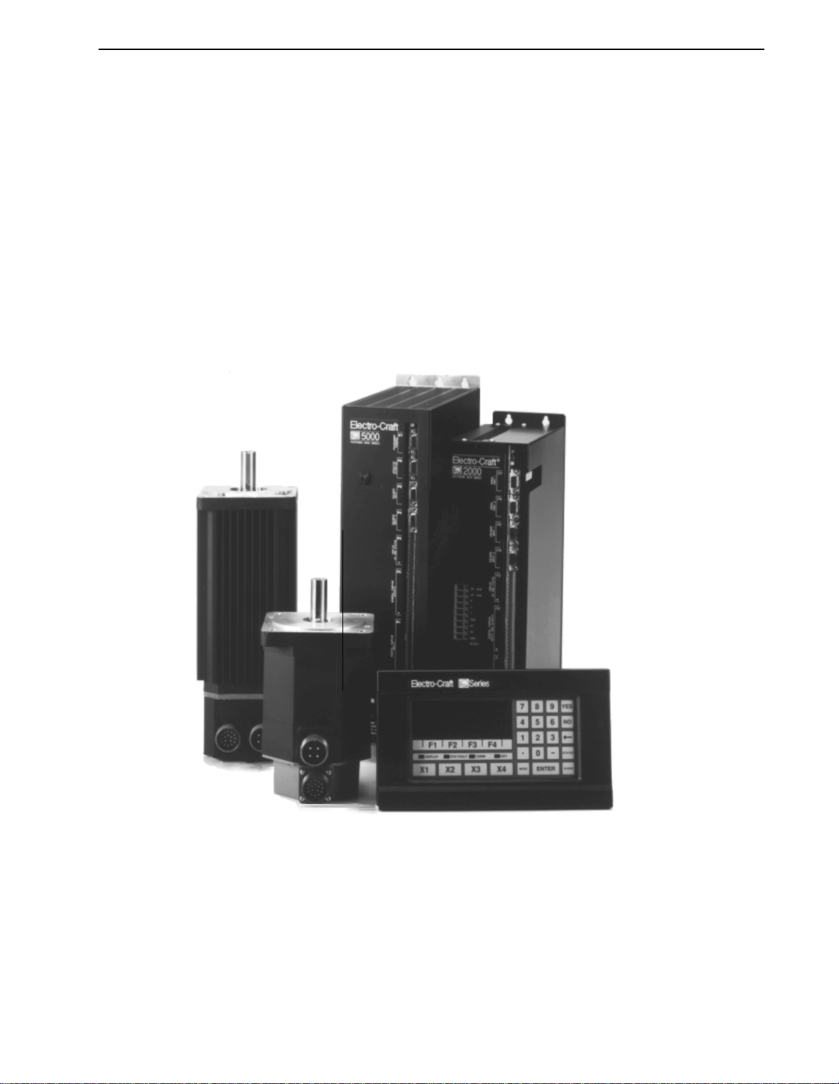
FIGURE 1.1 IQ 2000/5000 Product Family

1-2 Getting Started
P/N 0013-1027-005 Rev A
Functional Description
The IQ 2000/5000 system is for use as a servo drive and control system in industrial machinery.
It is intended to be used as a system comprised of at least a motor and a PDM. The PDM is not
intended foruse with motors other than Electro-Craftmotors as specified in this manual. PDMs
areintendedtobepermanentlyconnectedtothesupply,notforportableequipment.Themotors
are not intended to be directly connected to the supply and must only beconnected to a suitable
Electro-Craft drive. The system is intended for use in a normal industrial environment (refer to
Chapter 6, “Specifications”) and precautions must be taken during storage, handling, installa-
tion and use to ensure that it does not encounter extreme environments exceeding the
specifications.
The IQ 2000/5000 motion control system is a positioning drive system which integrates a high
performance sinusoidal brushless motor velocity controller and a programmable position con-
troller into a single package. Traditional motion controller architecture uses separate drive and
position control modules, with an analog interface between individual components. The
IQ 2000/5000 motion controllers use advanced microprocessor technology to control both posi-
tion and velocity with a single processor, eliminating the need for any analog interface. The
single processor architecture eliminates the problems associated with analog circuitry, such as
offset and thermal drift. Both the velocity and position control loops are closeddigitally, so gain
parameters are stored as numbers which give repeatable results over time and from controller
to controller.
The IQ may be used as a distributed motion control element integrated with a host computer
in a flexible automation system or as a stand-alone, programmable motion controller. Optically
isolated I/O and power supplies are integrated into the products.
The electronic gearing feature allows the closed-loop axis to follow a second (master) encoder
at a programmable ratio. A multi-axis addressing scheme (multi-drop operation) allows mul-
tiple IQs to be controlled from a host computer over a single serial communications link.
An IQ 2000/5000 system consists of a Positioning Drive Module (PDM), which controls the
position, velocity and torque of the motor; a Personality Module which plugs into the PDM to
match the controller with the motor used; a brushless motor with an integral optical encoder
for feedback; a Power Supply Module, integral to the IQ-2000 PDMs, and separate for the IQ-
5000 PDMs; and an optional Operator Terminal. Option cards for I/O or memory expansion or
other application specific functions mount directly on the PDM.
Combinations of matched PDMs and motors are available which provide continuous torques
of 0.34 Nm to 88.14 Nm (3 inch/pound to 750 inch/pound), and speeds up to 6000 RPM.
IQ 2000/5000 System Overview
An IQ 2000/5000 motion control system consists of a number of components connected to
accomplishaspecificfunction.Thissectionprovidesabriefoverviewofthevariouscomponents
of the IQ 2000/5000 motion control system.
IQ Master for Windows
IQ Master is a Windows based software package that provides the user interface to the PDM.
Itisused toeditand compile applicationprograms,and toconfigure,monitor, andtroubleshoot
the PDM.
Positioning Drive Module (PDM)
The IQ 2000/5000 PDM is a self-contained single axis programmable motion controller. The
PDM provides control and power for the brushless servo motor. Motion programs are stored
inonboardnonvolatilememory.TwoRS-232/RS-422serialportsprovidecommunicationswith
thepersonalcomputerandtheoptionalOperatorTerminal.OpticallyisolateddigitalI/Oallows
simple machine interfacing and control.

Getting Started 1-3
IQ 2000/5000 Installation Manual
PDMs are manufactured in different packages which cover a wide range of power capability.
The IQ-2000 Series PDMs incorporate an integral power supply in each PDM, and supply con-
tinuous torques of 3 to 450 inch–pounds in combination with standard motors. The IQ-5000
Series PDMsuse aseparate powersupply module, which can be shared among multiple PDMs,
and provide continuous torques of 20 to 750 inch pounds with the standard motors.
IQ-2000 PDMs
The PDM-10, PDM-20, PDM-30, PDM-75, and PDM-150B are rated for 10, 20, 30, 75, and 150
amp peak currents respectively. These modules are packaged with an integral power supply to
achieve a small size.
Input power to a PDM-10, PDM-20, or PDM-30 is single phase 115 or 230 VAC. Input power to
a PDM-75 or PDM-150B is three-phase 115 or 230 VAC. The input power may be optionally
isolated through a transformer. These PDMs have a built-in solid state “soft charge” of the
internal DC bus capacitor. They also include a built-in dissipative shunt regulator that provides
synchronousmotordynamicbraking.ThePDMsallowuseofanoptionalexternalshuntresistor
for applications requiring higher shunt power capability than provided by the internal shunt
resistor.
FIGURE 1.2 IQ 2000/5000 System Components

1-4 Getting Started
P/N 0013-1027-005 Rev A
IQ-5000 PDMs
The PDM-25, PDM-50, PDM-100, and PDM-150/150X are rated for 25, 50, 100, and 150 amp
peak currents respectively. These higher power PDM modules use a separate power supply
module (PSM-50 or PSM-125), which may be shared among multiple PDMs to achieve the most
economical system package. Other than the packaging and power ranges, the IQ-5000 is iden-
tical to the IQ-2000 from a setup and programming perspective.
Power Supply Module (PSM)
The power supply module is only required for IQ-5000 systems. The Power Supply Module
(PSM) can supply DC power to as many as six PDM modules. The only input to the PSM is 100–
240 VAC single or three phase power. The input power may be optionally isolated through a
transformer. The output is a two wire DC bus. The PSM requires no adjustments, protects itself,
provides troubleshooting diagnostics, and has a built-in solid state “soft charge” of the DC bus
capacitors. It also includes a built-in dissipative shunt regulator that provides quick discharge
of the DC bus capacitors and doubles as an emergency synchronous motor dynamic brake.
Motor
A wide range of Electro-Craft F-Series, H-Series, N-Series and W-Series permanent magnet
synchronous motors, and the I-Series induction motors are available for use with the PDM
modules. Each motor includes an integrally mounted encoder. Most motors are available with
options including spring set brake and/or shaft oil seal. Military Standard (MS) connectors are
standard for all H-Series and F-Series motors.
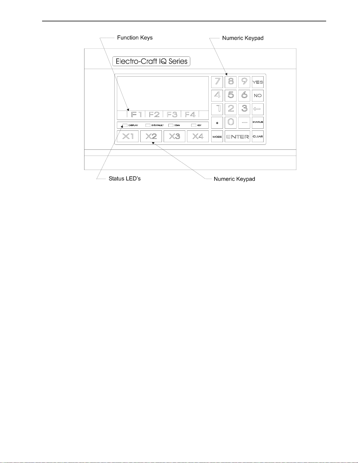
Operator Terminal
The optional Operator Terminal is a rugged man/machine interface device. It allows the
machine operator convenient access to status information, program variables, and control func-
tions,plusmessagedisplaycapabilities.TheOperatorTerminalhasabright4lineby20character
vacuum fluorescent display and a sealed membrane keyboard with tactile feedback.
The Operator Terminal displays multiple status screens for monitoring and diagnostics. Four
soft function keys are available to perform up to twenty-four (24) predefined functions, some
of which are selecting and running a program, jogging the system, and stopping a program.
The user program may display messages and prompts on the screen, and receive input from
the keypad. Four additional user programmable keys provide extra flexibility within a user
program. Input power to the Operator Terminal is 115 or 230 VAC, or optionally 24 VDC or
24 VAC.
Personality Module (PM)
ThePersonality Moduleis anonvolatilememory devicewhich storestheinformation necessary
tocustomizeanIQ 2000/5000PDMforaspecificapplication.ThePMholdsparameterstomatch
the encoder feedback, motor and the drive, as well as user programs and parameters. A Per-
sonality Modulemay be physicallyremovedandtransferredtoanotherPDM if thereplacement
of a PDM is necessary to simplify servicing the machine. The Personality Module data can also
be saved in a computer file and loaded into the IQ 2000/5000 using the File > Transfer dialog
box in IQ Master.
Manuals
The manuals are conveniently broken into two volumes. This manual contains all the informa-
tion required for mounting and wiring the motor and PDM. The IQ Master Software Manual
contains all the information that a user and programmer requires to quickly setup the PDM and
develop programs for the PDM.
Getting Started 1-5
IQ 2000/5000 Installation Manual
Personal Computer (PC)
A user supplied Personal Computer is required to run IQ Master software. The minimum com-
puter requirements to run this software are contained in the IQ Master Instruction Manual.
Option Cards
Each PDM can have an option card mounted on its main control board, inside the PDM cover.
The option card mounting allows either a half-size or full-size option card. The PDM has a
connectorthatconnectstheoptioncardtothePDMpowersuppliesandmicroprocessorthrough
a ribbon cable.
The option cards currently available include a combination Memory and I/O Expansion Card
and an I/O Expansion Card. Refer to“Part Numbers of Interface Cards” on page 7-4.
Memory and I/O Expansion Card
Additional memory and I/O may be added vwith a Memory and I/O Expansion Card. This
board adds the following memory, input and output capabilities to the PDM.
◆32 Kilobytes of additional nonvolatile memory to the base PDM for the storage of up to 32
additional programs
◆32 TTL Inputs
◆16 TTL Outputs
◆four 12-bit Analog inputs
FIGURE 1.3 IQ 2000/5000 Operator Terminal

1-6 Getting Started
P/N 0013-1027-005 Rev A
I/O Expansion Card
AdditionalI/OmaybeaddedwithanI/OExpansionCard.Thisboardaddsthefollowinginput
and output capabilities to the PDM.
◆32 TTL Inputs
◆16 TTL Outputs
NOTE:
The digital inputs and outputs on the I/O expansion cards are 5 Volt TTL signals which are not
optically isolated.
I/O Interface Card
ADINrail mountedinterfacecardforI/Oconversion.The interfacecardconverts the IQinputs
andoutputsfromsinking(activelow),whichiscommonintheUSAbutunacceptableinEurope,
tosourcing(activehigh).Theinterfacecardmustbemountedinthesameenclosureasthedrive.
Installation instructions are provided with the card.
Accessories
Transformers
Multi-tap singlephase andthreephase isolationtransformersareavailableinavarietyof power
ratings for line voltage matching. See “Part Numbers of Transformers” on page 7-4.
Auxiliary Power Supply Module (IQ-5000 Only)
An auxiliary power supply module (PSM-AUX) is available to supply DC power to the logic
supplies of up to four PDMs if the PSM is off. The PSM-AUX uses single phase 115 VAC power
as the input. This option is only necessary for the IQ-5000 with the separate power supply
module. The IQ-2000 PDMs with an integral power supply include the auxiliary supply in the
PDM.
The PSM-AUX option is useful if PDM logic power must stay on even when the motor supply
(the PSM) is off. Absolute positioning is one example of when the PSM-AUX would be useful,
since position information is maintained as long as logic power is on. Another example would
be maintaining PDM logic power so the PDM serial interface could be used for troubleshooting
and diagnostics. Refer to Figure 2.24 on page 2-31 for additional information on the use of the
PSM-AUX and optional PSM-AUX isolation transformer. See “Part Numbers of Power Supply
Modules” on page 7-1.
Cables
Motor power cables with connectors are available in four standard lengths 3, 7.6, 15 and 23
meters (10, 25, 50 and 75 ft.). Motor encoder cables with connectors and fifteen pin “D” connec-
tors are available in the four standard lengths. Nine pin serial cables are available in 3 and 7.6
meter (10 ft. and 25 ft.) lengths. See “Part Numbers of Cables” on page 7-2.
Motor Connectors
Mating connectors are available if you choose to build your own motor cables. See “Part Num-
bers of Motor Mating Connector Kits” on page 7-3.

IQ 2000/5000 Installation Manual
CHAPTER 2: Installation
This chapter explains the physical mounting of each of the individual components associated
with an IQ 2000/5000 system. Refer to the drawings listed below for assistance.
Prior to installation of the IQ 2000/5000 system, verify that all the necessary components are
available.EachaxisofmotionrequiresanIQ 2000/5000PositioningDriveModule(PDM),either
IQ-2000 or IQ-5000 and a motor. There must be one PDM for each motor. If IQ-5000 PDMs are
used, there must be at least one power supply module for the system.
Optional components of the system are an IQ 2000/5000 Operator Terminal, a transformer, an
Auxiliary power supply for the IQ-5000, an external shunt for the IQ-2000, and any IQ 2000/
5000 option cards.
A personal computer, with IQ Master software will be required to setup the system. The PC is
customer supplied.
Machines which integrate the PDM must be designed to meet all regulatory requirements for
locations where the machine may be brought into use. In the U.S. these include but are not
limited to UL and NEC requirements. In Europe, machines must comply with the Machinery
Directive and the basic standards which this directive references.
TABLE 2.1 Mounting and Related Diagrams
Figure Part Number Title Page
2.22 9101-0131 IQ-5000 Transformer Outline Diagram 2-29
2.23 9101-0132 IQ-5000 Transformer Load Regulation Curve 2-30
2.24 9101-0134 PSM-AUX Outline and Connection Diagram 2-31
2.25 9101-1056 IQ-2000 Transformer Outline Diagram 2-32
2.26 9101-1057 IQ-2000 Transformer Load Regulation Curve 2-33
2.27 9101-1328 External Shunt Mounting and Connection Diagram 2-34
2.28 --- External Shunt Wiring Examples 2-34
2.29 9103-0152 24V Sourcing I/O Conversion Card 2-35
!DANGER: Only qualified electrical personnel familiar with the
construction and operation of this equipment and the hazards
involvedshouldinstall,adjust,operate,orservicethisequipment.
Read and understand this manual and other applicable manuals
in their entirety before proceeding. Failure to observe this precau-
tion could result in severe bodily injury or loss of life.

2-2 Installation
P/N 0013-1027-005 Rev A
Fusing Requirements
Fusing for the IQ-5000 differs from the IQ-2000 in that the IQ-5000 utilizes a separate power
supply. Since thepower supply can provide power to up to six drives, the “4 times motor FLA”
rule does not apply.
IQ-2000 Short Circuit Protection
In the United States, the National Electrical Code (NEC) specifies that fuse selection must be
based on the motor full load amperage (FLA), which is not to be confused with the drive input
current. The largest fuse allowed under any circumstances is four times the motor FLA. There-
fore the largest fuses permissible for use are four times the motor FLA (marked on the motor)
converted to an RMS value. The IQ-2000 has been evaluated and listed by Underwriter Labo-
ratories®Inc.accordingtoUL508C,withfusessizedasfourtimesthecontinuousoutputcurrent
(FLA) of the drive.
In almost all cases, fuses selected to match the drive input current rating will meet the NEC
requirements and provide the full drive capabilities. Dual element, time delay fuses should be
used to avoid nuisance trips during power initialization due to inrush current.
Short Circuit Current Rating with No Fuse Restrictions
Suitableforuseonacircuitcapableofdeliveringnotmorethan5000RMSsymmetricalAmperes,
240 Volts maximum.
Short Circuit Current Rating with Fuse Restrictions
Suitable for use on a circuit capable of delivering not more than 200,000 RMS symmetrical
Amperes, 240 Volts maximum, when protected by high interrupting capacity, current limiting
fuses (Class CC, G, J, L, R, T).
Motor Overload Protection
This drive utilizes solid state motor overload protection which operates:
◆within 8 minutes at 200% overload
◆within 20 seconds at 600% overload
IQ-5000 Short Circuit Protection
In the United States, the National Electrical Code (NEC) specifies that fuse selection must be
based on the motor full load amperage (FLA), which is not to be confused with the drive input
current. The largest fuse allowed under any circumstances is four times the motor FLA. There-
fore the largest fuses permissible for use are four times the motor FLA (marked on the motor)
converted to an RMS value. The IQ-2000 has been evaluated and listed by Underwriter Labo-
ratories®Inc. according to UL508.
In almost all cases, fuses selected to match the drive input current rating will meet the NEC
requirements and provide the full drive capabilities. Dual element, time delay fuses should be
used to avoid nuisance trips during power initialization due to inrush current.
Short Circuit Current Ratings and Fuse Requirements
Suitable for use on a circuit capable of delivering not more than 5,000 RMS symmetrical
Amperes, 240 Volts maximum, when protected by
◆PSM 50: class R fuses rated 40A
◆PSM 125: class R fuses rated 90A
This manual suits for next models
1
Table of contents
Other Electro-Craft DC Drive manuals


Popular DC Drive manuals by other brands

Green Creative
Green Creative 24T5HODRIVER/2CH installation guide

Johnson Controls
Johnson Controls VFD67 Series Quick start commissioning guide

Idex
Idex ISMATEC REGLO-Z Digital operating manual

YASKAWA
YASKAWA CR700 Technical manual

YASKAWA
YASKAWA Z1000 CIMR-ZU*A Series User's manual supplement

BAFANG
BAFANG MM G510.500 18 027 manual

Masterflex
Masterflex P/S 850-3010 operating manual

Santerno
Santerno Sinus Penta user manual

BONFIGLIOLI
BONFIGLIOLI Agile Series Application manual Functional Safety

KB Electronics
KB Electronics KBAC-24D Installation and operation manual

ABB
ABB ACS880-07LC Hardware manual

eldoLED
eldoLED LINEARdrive 720D quick start guide


