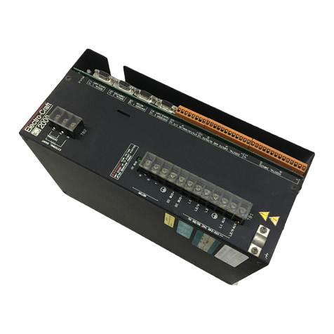
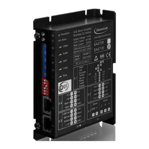
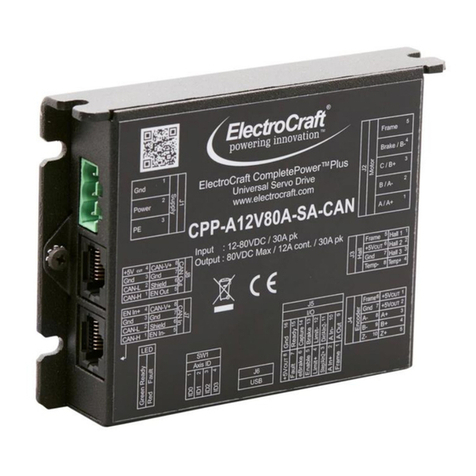
Electro-Craft BRU Series User manual

BRU-200 and BRU-500
Brushless Drives
Instruction Manual
Electro-Craft Servo Products
R

(
r
r
(
( Electro-Craft
BRU-200 and BRU-500
Brushless Drives
Instruction Manual
P/N 0013-1028-001
Revision
B
Reliance
Motion
Control,
Inc.
6950
Washington
Avenue
South
Eden Prairie, MN 55344
612-942-3600
Technical
Support:
800-328-3983

DANGER
ONLY QUALIFIFED ELECTRICAL PERSONNEL FAMILIAR WITH THE
CONSTRUCTION AND OPERATION OF THIS EQUIPMENT AND THE HAZARDS
INVOLVED SHOULD INSTALL, ADJUST, OPERATE OR SERVICE THIS EQUIPMENT.
READ AND UNDERSTAND THIS MANUAL AND OTHER APPLICABLE MANUALS
IN
THEIR ENTIRETY BEFORE PROCEEDING. FAILURE TO OB_SERVE THIS
PRECAUTION COULD RESULT
IN
SEVERE BODILY INJURY OR LOSS OF LIFE.
WARNING
THE USER MUST PROVIDE
AN
EXTERNAL, HARDWIRED EMERGENCY STOP
CIRCUIT OUTSIDE THE CONTROLLER
CIRCUITRY
THIS CIRCUIT MUST DISABLE
THE SYSTEM
IN
CASE OF IMPROPER OPERATION. UNCONTROLLED MACHINE
OPERATION
MAY
RESULT IF THIS PROCEDURE IS NOT FOLLOWED. FAILURE TO
OBSERVE THIS PRECAUTION COULD RESULT
IN
SEVERE BODILY INJURY.
Copyright© Reliance Motion Control, Inc. 1995. All rights reserved.
The information contained in this manual
is
subject
to
change without notice.
Electro-Craft is a registered trademark
of
Reliance Electric Company
or
its subsidiaries.
Tandy is a registered trademark
of
Tandy Corporation.
IBM is a registered trademark
of
International Business Machines Corporation.
INTEL
is
a trademark
of
Intel Corporation.
AMP is a trademark
of
AMP Incorporated.
Molex
is
a registered trademark
of
Molex Incorporated.
(
(
(

(
r
Table
of
Contents
TABLE
OF
CONTENTS
SECTION I - INTRODUCTION
1.1 Purpose ...............................................
..
........................................................................................................ 1
1.2 Product Descripti
on
..........
..
.......................................................
..
.............................
..
....
..
....
......
..
.
...
.......
..
... 1
1.2.1 Power Supply Modules (BRU-500 Only) .................................................
..
...........
..
.
..
.........
..
.......... 2
1.2.2 Drive
Mcx:lules
..........................
..
........
..
......
..
.................................
...
......................................
..
....
.... 2
1.2.3 Motors and Encoders..............................................................................................................
..
...... 3
1.2.4 Transformers .........................................................................................................
..
........................ 3
1.2.5 Auxiliary Power Supply (BRU-500 Only) ........................................................................................ 3
SECTION
11-
SPECIFICATIONS
2.1 Drive Mcx:lule Specifications......................................................................................................................... 4
2.2 Power Supply Module Specifications
(BRU
-500 Only)..................
..
.......
......
...................
..
....
..
..
....
.............. 5
2.3 S-Series Motor Specifications (TENV) .....................................
..
.........................
..
...................
..
..
...
....
......... 6
2.4 F-Series Motor Specifications (TENV).......................................................................................................... 7
2.5 1-Series Motor Specifications (BRU-500 Only) ..............................
..
..
...........................................................7
2.6 Encoder Specifications.................................................................................................................................8
2.7 Transformer Specifications.....
....
.................................................................................................................. 8
2.8 Maximum Power Losses
....
...................
...
..................
..
.................................................................................9
SECTION
Ill-INSTALLATION
3
.1
Mounting the Power Supply and Drive Modules .............................
...
....................................................... 10
3.2 Power Wiring ....
..
....
..
.........................................................
...
...........
..
........
...
............................................... 10
3.2.1 BRU-500 Power Wiring....................................................................................
...
........................... 10
3.2.2 BRU-2
00
Power Wiring.............................................................. ......................
..
............................
11
3.3 Motor Mounting and Wiring ........................................................................................................................
11
3.4 External Shunt Mounting and Wiring (BRU-200 DM-30
Opt
ion Only) ......................................................
11
BRU-200
/B
RU-500
Bru
sh
less
Dr
ives Instruction Manual iii

Table
of
Contents
SECTION
IV
-INTERFACE CIRCUITRY
4
.1
Drive Module Interface Connectors............................
..
.....
...
..
..................................................................
..
15
4.2 Drive Module Interface Signal Specifications ....................................
..
...................................................... 16
4.3 Power Supply Module Interface Connector
(BRU
-500 Only)...........................................................
....
.....
20
4.4 Power Supply Module Interface Signal Specifications (BRU-500 Only) ...................................................
20
SECTION
V-
START-UP AND ADJUSTMENTS
5.1 Initial Start-Up Procedure ...
..
...
......................
...
.....................................................................
..
...................
21
5.1.1 Initial Start-Up Procedure (BRU-500) ....................................
..
.....................................................
21
5.1.2 Initial Start-Up Procedure (BRU-200) ....
...
..........
..
............
..
.......................................................... 22
5.2 Adjustments............................
..
............................................................
...
.......................
..
.......
...
.
..
.............. 23
5.
2.1
Power Supply Module Adjustments (BRU-500 Only) .
...
..
..........
..
..........
..
....................................23
5.2.2 Drive Module Adjustments.....................................................................
..
..................
...
.
..
........
..
... 23
5.2.3 Serial Interface Operation ......................................................................
..
...
..
.
..
..
...................
..
..
...
. 27
5.2.3.1 User Terminal Requirements ..................................................................................
..
...... 27
5.2.3.2 Operating the User Terminal..................................
..
.......................................................
27
5.2.3.2
.1
Help Page
..
.....................................................
...
...
..
...
..
...................................... 27
5.2.3.2.2 Status Page
..
......................................................................................................29
5.2.3.2.3 Setup Page ...........................................................
..
...................
..
.......
..
.
..
...
...
....
31
5.2.3.3 Multi-Drop Host Mode Serial Protocol
..
......................................................................... 35
5.3 Tuni
ng
Procedure...................................................................
...
..
................................................................36
5.3
.1
Using Auto-Tune Mode ...............................................
..
................................................................ 36
5.3.2 Using Tune Mode..........................................................
..
.............................................................. 38
5.4 Personality Module Installation.......................
..
.......................
...
.
..
.............................................................43
SECTION VI -TROUBLESHOOTING AND MAINTENANCE
6.1
Introduction...............................
..
........................
..
.........................................................................
....
......... 44
6.2 LED Diagnostic lnfonnation..........................................................
...
.............................................
...
.
..
....
..
.. 44
6.2.1 Power Supply Module LEOs (BRU-500 Only)
..
...................
..
.......................................................44
6.2.2
Dr
iv
e Module
LEOs
.............................................................................
..
..................
..
.....................44
6.3 Serial
Unk
Diagnostic Information.............................................................................................................. 45
iv
BRU-20
0/B
RU-500 Brushless Drives Instruction Manual

r
(
(
Table
of
Contents
SECTION VII -OPTIONAL ACCESSORIES
7.1
PRO-Series Controller
Kit
Installation Instructions ...............
..
................................................................... 46
7.2 Spindle Orient and Auxiliary Function Card Installation Instructions
(BRU-500 Only) ..............................................................................................................................46
7.3 BRU-Series Control Station .....................
...
............................................................
..
.................................. 47
7.4 RS232C/RS422 Converter..............................................................................
..
..
..
.........
..
............
..
.
...
..
....... 49
SECTION
VIII-
APPLICATION GUIDELINES
8.1
Torque Sharing Operation of BRU-Series Drives..........................................................
..
...
..
..
..
...
.
....
.......... 50
8.1.1 General Description
..
...
..
...................
...
.................................
..
.
...
..
.
... ...
....
..
.......
...
..
..
..
................... 50
8.1
.2 Theory
of
Operation ..........................
..
....
..
..
....
..
...
..
...
..................
...
............................................... 50
8.1.2.1 Multiple Slave Drives .......................................................................................................
51
8
.1
.2.2 Unequal
Tor
que Sharing ..
..
.
...
.........
...
.....
...
...
..
.................................................
..
...........
..
51
8.1.3 Set-Up Procedure..........................
...
...........
...
......
..
......................................................
..
.
..
...
..
....
..
. 52
8.1.
3.1
Wiring Instructions....................
..
...........
...
...............................................................
...
..... 52
8.1.3.2 Tuning.................................................................
..
.
..
...
..
.................................................
..
52
SECTION
IX-
REPLACEMENT PARTS
9.1
Power Supply Modules (BRU-500 Only)
..
..
..
.....
...
.................
....
...
...
.........................
...
............................
...
55
9.2 Drive Modules........
..
....................................................................................................................................55
9.3 Personality Modules..........
..
........................................................................................................................56
9.4 Motors
..
.........................
..
.................
..
.....................................................
..
.................................
...
.
..
......
...
... 56
9.5 PRO-Series Kits .................................................................................................................................
..
..
..
.... 57
9.6 Spindle Orient and Auxiliary Function Card (BRU-500 Only).................................................................... 57
9.7 Cables.................
...
...........................................................................................................................
...
........ 57
9.8 Transformers ....................................................................................................................................
..
..
....... 58
9.9 Motor Mating Connectors
..
...............................
...
.
...
.
...
........
..
.........................
....
........................................ 58
9.10 Motor Shaft Seal Kits
..
............................................................................................................................... 58
SECTION
X-
CUSTOMER REFERENCE DRAWINGS
10.1
List of Drawings....................
..
.................
...
.................
..
..
.......
..
....................................................
..
.
..
...
....
. 59
BRU-200/BRU-500 Brushless Drives Instruction Manual v

Table
of
Contents
INDEX
Index....................................................................................................................................
..
............................. 54
LIST
OF
FIGURES
Figure
1-1
BRU-500 Series Servo and Spindle Drives..........................
...
........
...
............................................... 1
Figure 1-2 BRU-200 Series Servo Drives..
...
.......................................................................................................2
Figure 3-1 S-Series Motor Connections.................................................................................................
..
........ 12
Figure 3-2 F-Series Motor Connections...........................................................................................................
13
Figure 3-3 I-Series
Motor
Connections ............................................................................................................ 14
Figure
5-1
PSM
Jumper
Locations•..................................................................
...
.............
..
.............................. 25
Figure 5-2
OM
Jumper
and Personality Module Locations......................
...
........................
...
..
.................
...
...26
Figure 5-3 Serial Terminal HELP PAGE............................................................................................................ 28
Figure 5-4 Software and Personality Module Identification.............................................................................28
Figure 5-5 Serial Terminal STATUS PAGE ....................................................................................................... 29
Figure 5-6 Serial Terminal STATUS PAGE After Fault..................................................................................... 29
Figure 5-7 Serial Terminal SETUP PAGE (Velocity Mode) ..............................................................................
31
Figure 5-8 Serial Terminal SETUP PAGE (Torque Mode) ............................................................................... 32
Figure 5-9 Serial Terminal SETUP PAGE (Tune Mode) .....................................
..
............................................ 32
Figure 5-10 Serial Terminal SETUP PAGE (Auto-Tune Mode)........................................................................ 32
Figure
5-11
Control Block Diagrams
of
Operating Modes.....................................
...
................ ...................
...
39
Figure 5-
12
Typical Small-Signal Response
for
Well-Tuned System.............................................................. 42
Figure 5-13 Personality Module lnstallation ..................................................................................................... 43
Figure
7-1
Sp
indle Orient and Auxiliary Function Applica
tion
(BRU-500 Only).............................................. 46
Figure
7-2
BRU-Series Control Station..............................................................
...
.
...
........................................ 47
Figure 7-3
BRU
-Series Control Station Connection Diagram ......................................................................... 48
vi BRU-200/BRU-500 Brushless Drives Instruction Manual

(
Table
of
Contents
LIST OF FIGURES (Cont.)
Figure
8-1
Examples
of
Torque Sharing Operation.........................................................................................
51
Figure 8-2 Recommended Wiring
for
Torque Sharing
when Motors Rotate in Same Direction..............................................................................................
...
53
Figure 8-3 Recommended Wiring
for
Torque Sharing
when
Slave
Motors Rotate Opposite
of
Master Motor ..............................
..
............................................................. 54
Figure
9-1
Personality Module Model Number Description .........................................................
..
................. 56
Figure 9-2
Motor
Model Number Description .................................................................................................. 56
LIST OF APPENDICES
APPENDIX
A-
Getting Started With the
Tandy
102 Terminal ................................
..
........................................60
APPENDIX
8-
User Terminal Communication Codes .....................................................................................
61
APPENDIX C Getting Started With an IBC PC Terminal..................................................................................62
APPENDIX D Communication Problems and Possible Cures ......................................................................
..
63
BRU-200/BRU-500 Brushless Drives Instruction Manual
vii

(
l

(
r
Introduction
SECTION I - INTRODUCTION
1.1
Purpose
This manual describes the Electro-Craft BRU-Series brushless servo drives and spindle drives along with
standard Electro-Craft motors recommended for
use
with the BRU-Series drives. The manual is intended
for use
by
qualified engineers
or
technicians directly involved in
the
installation, operation, and field level
maintenance of the drives and motors.
1.2 Product Description
The BRU-500 is a high performance sinusoidal brushless industrial drive employing a modular package
suited
to
single
or
multi-axis applications. The drive modules can powerS-Series and F-Series permanent
magnet synchronous motors as servo drives
or
1-Series
squirrel cage induction motors
as
spindle drives.
All drives share a common power supply
to
achieve the most economical system package.
1-1
shows
the
standard BRU-500 components.
The BRU-200 is a high performance sinusoidal brushless industrial drive employing a
modu
l
ar
package
suited
to
single or multi-axis applications. The drive modules
power
S-Series and F-Series permanent
magnet synchronous motors. Figure 1-2 shows the standard
BRU
-200 components.
For single axis positioning applications, the Electro-Craft PRO-Series controller cards are available as PRO-
Series Controller Kits
to
be integrated into the BRU-Series drive module. This eliminates the need
for
a
separate controller package.
Figure 1-1 BRU-500 Series Servo and Spindle Drives
BRU-200/BRU-500 Brushless
Dr
ives Instruction
Manu
al 1

2
Introduction
Figure 1-2 BRU-200 Series Servo Drives
A brief description
of
the BRU-Series major components follows.
1.2.1 Power Supply Modules (BRU-500 Only)
The power supply module
(PSM)
can supply DC power
to
as
many as slx servo
or
spindle drive modules.
The
AC
voltage input
to
the
PSM
is non-isolated
or
isolated three phase power. The output, which is daisy-
chained
to
the drive modules, is a
two
wire DC bus. The PSM requires
no
adjustments, protects itself,
provides trouble-shooting diagnostics, and has a built-in solid-state "soft charge•
of
the DC bus capacitors
to
reduce AC inrush currents. It also includes a built-in dissipative shunt regulator that provides quick
discharge
of
the DC bus capacitors and doubles as an emergency synchronous motordynamic brake.
1.2.2 Drive Modules
The drive modules (OM) provide control and power for either S-Series and F-Series permanent magnet
synchronous motors
or
!-Series squirrel cage induction motors (BRU-500 only). The
OMs
are available
in
a
range of current ratings
to
best complement the variety
of
available motors. The
OM
control circuitry
utilizes a 16 bit microprocessor
to
provide high performance and a simple serial interface from a host
computer
or
user programming terminal
to
the servo drive.
All set-up and tuning is performed by a personality module
(PM)
which plugs into the
DM.
The
PM
customizes the
DM
for
each specific motor and encoder type. The standard decimal line count encoders
are factory-installed on the motors.
BRU-200/BRU-500 Brushless Drives Instruction Manual

r
Introduction
A standard RS-232/RS-422 serial interface is
used
to modify tuning, change limit values,
or
monitor
variables/status in the BRU-Series
dr
ive modules. Any changes made through the serial interface
can
then
be
stored in the
PM.
A VT-52 compatible serial terminal is required for the easy-to-use menus.
Refer to Secti
on
5.2.3.1 for user terminal requirements. Alternatively, a multi-drop host mode
communication protocol is also available for direct connection to computer hosts. Refer to Section
5.2.3.3.
1.2.3 Motors and Encoders
A wide range
of
Electro-Craft S-Series and F-Series permanent magnet synchronous motors
and
1-
Series induction motors are available for use wi
th
BRU-Seri
es
dr
ives. Each motor includes
an
internally
mounted encoder. The BRU-Series also provides the encoder signals for the position controller
to
use
for the most economical system. Most motors are available with optional spring-set brake, optional
shaft oil seals, and/or optional fanpack. The synchronous motors have a rear shaft available for
mounting optional feedback devices.
1.2.4 Transformers
Multi-tap three phase isolation transformers are available in a variety of power ratings for line voltage
matching for the BRU-500. A multi-tap single phase isolation transformer is available for line voltage
matching for the BRU-200.
1.2.5 Auxiliary Power Supply
An
auxiliary power supply module (PSM-AUX) is available to supply DC power to the logic supplies
of
up to four DMs
if
the PSM is turned off. The PSM-AUX uses single phase 115 VAC power as the input.
The PSM-AUX option
is
used
if
DM
logic power must stay
on
even when the motor supply (the PSM)
is
turned off. Absolute positioning with PRO-Series controller kits is
one
example where the PSM-AUX
would
be
used
. Another example would be maintaining DM logic power
so
that the DM serial interface
could
be
used for trouble-shooting and diagnostics. See drawing
91
01-0134 in Section X for additional
information
on
use
of
the PSM-AUX
and
the optional PSM-AUX isolation transformer.
The auxiliary power supply is built into the BRU-200 drive modules
as
standard equipment. See
drawing
91
01-1329 in Section X for additional
in
formation.
BRU
-200/BRU-500 Brushless D
ri
ves Instruction Manual 3

4
Specifications
SECTION
II
-SPECIFICATIONS
2.1
Drive Module Specifications
BRU-500 Model
Continuous
Amps[1]
Peak Amps[1
I
Bus Voltage
Command Signal
Input Range
Ambient Temp.
Weight
BRU-200 Model
Continuous
Amps
[1]
Peak Amps
[1
1
Input Volts
Internal DC
Bus Voltage
Command Signal
Input Range
Continuous
Shunt Power
[21
Peak Shunt Power
[21
Ambient
Temp
.
We
ight
DM-25
20
25
DM-50 DM-100
40 50
50 100
125-375 VDC
(325 VDC with 230 VAC input)
± 10 VDC (13.3k Ohms impedance)
32o-122oF (0°-50°
C)
24.2 lbs
(11
.0
kg)
DM-20
10
DM-30
15
10 20
100-240 VAC RMS (Single Phase)
141-340 VDC
(325 VDC with 230 VAC Input)
± 10 VDC (13.3k Ohms impedance)
sow
4.
5kW
32°-122oF
(0
°-50°
C)
15 lbs (6.8 kg)
30
peak value
of
sine wave per phase
DM-150 DM-150X
65
85
150 150
[1
1
[2
] DM-30 has provision
for
optional external shunt resistor that provides 200 W continuous and
6000 W peak shunt power. See drawing 9101-1328 in Section X
for
additional details.
BRU-200/BRU-500 Brushless Drives Instruction Manual
(

(
Specifications
2.2
Power Supply Module Specifications {BRU-500 Only)
BRU-500 Model PSM-50 PSM-125
Input
Volts 88-265
VAC
RMS (Three Phase)
Output
Volts 125-375 VDC
(325 VDC
with
230 VAC
Input
)
Continuous
Amps
(DC) 50 100
Peak Amps (DC) 150 450
Continuous
600W
1200W
Shunt Power
Peak Shunt Power
20kW
40kW
Ambient Temp.
32·
-122· F
(o
•
-so
·
C)
Weight 26.2
lbs
(11
.9
kg
)
BRU-200/BRU-500 Brush/ess
Dr
ives Instruction Manual 5

6
Specifications
2.3 S-Series
Motor
Specifications (TENV} [5]
[1
1
[2]
[3]
[4]
[SJ
Model S-2003 5-2005 5-3007 S-3016 5-4030
stall
Torque
(ll>-inl
2. 7 5. 0 7. 0 20 30
(Mal
0.30 0. 56 0. 79 2. 26 3. 39
Speed
00
(rpll)
6000
6000 5000 5000
4000
Kt
121
1.
17
1.17
2. 5
2.5
4. 4
(Ha/A)
0.13 0.
13
0 .28 0.28 0.50
Ke
C3l
(V/lCrpll)
16
16 34 34
60
A
lohu)
7.3
2. 6 6. 6
1.3
2.0
L
t.HI
9. 7
4.1
12.0 3 . 4 9. 0
J
(lll-1n-s2J 0.
00007
0. 00013 0.00027 0. 00072 0 . 0022
(kg-112) .
000008
0.
00003
0.00008 0.00025
BRU-500
--
DM-25
Dlt-25
DM-25
BRU-200
DM-10
DM-
10
DM-10 DM-20 DM-20
maximum continuous operati
ng
speed
peak amps
of
per
phase sine wave
peak volts
of
line
to
line sine wave
phase
to
phase
totally enclosed nonventilated
5-4050 5-4075
60 90
6.
78
10
.2
4000
3000
4.4
6 . 7
0 .
50
0. 76
60
90
0.8 0.9
3.3
5.4
0.0041 0. 006
0.00046 0.00068
DM-50
DM-50
DM-30
OM-30
S-6100 S-6200
100
200
11.3 22.6
3000 3000
6 . 0 5 . 8
0.68
0.66
82
80
0.49
0. 18
4.4 2 . 2
0.012 0.021
0. 0013 0.
0024
llM-50
DM-100
--
BRU-200jBRU·500 Brushless Drives Instruc
ti
on
Manual
(
(
S-6300 S-8350
s-esoo
325 350 450
36.7
39.5
50.8
3000 2000 2000
6.2 7 . 6 8 . 2
0.
70
0.
86
0 .
92
85
104 112
0.12
0 . 13 0 .
10
1 .2 2 . 5 2 . 4
0.030
0.056
0.083
0 .0034 0. 0063 0. 0094
DM-150
DM-100 DM-150
---

r
Specifications
2.4 F-Series
Motor
Specifications (TENV) [5]
HodeL F-4030 F-fOSO F-4075 F-6100 F-6200 F-6300
StaLL
31
6l
82
1l5
175 245
a.>
3.5
6. 9 9. 3
t3.0
19.8
27.8
4000 4000 3000 3000
3000
3000
J::t
(2)
Clb-lniA>
4.8
4.8
6.5
6.3
6.2
6. 5
(IWA)
0.54 0.54 0.
73
0.
11
0. 10
0.73
ao
CV/Itrpa) 66
66
89
86
8S 89
R
C4l
(en.>
2. 24 0. 89
0.98
o.51
0.26
0.16
L
C4l
c.tO
6.8
3.3
3.<1
3. 3 1.7 1.1
J
Clb-1,...2)
0. 009 0.019 0.029
0.057
o.oss
O.t<l.f
ctv--2 > 0.
001
o.002t 0.0032 0.0064 0.0107 0.0162
8R0-500
DI'I-2S
01'1-50
01'1-50
01'1-50
01'1-100
01'1-100
BRU-200
01'1-20
01'1-30
DH-30
---
(1] maximum continuous operating
speed
[2] peak amps
of
per phase sine
wave
[3] peak volts of line
to
line
sine
wave
(4] phase
to
phase
[5] totally enclosed nonventilated
2.5 1-Series
Motor
Specifications (BRU-500 Only)
Cont. 30 Hin. Bose
Hox.
Rotor
HodeL
Power Rot ing Speed Speed
Inertia
Weight
Drive
Kg-m2f
kg
/L
bs
Module
kW
IH
P
kWIHP
RPH
RPH
lb-in-s
2
I-5300
5.
517
.4
7.5110
. 0 7500 6000 0.037 / 701154
DH-100
TEA0
0)
0.269
I-6600
11/14.7
151
20
7500 6000
0.073
1 108/238
DH-150X
TEA0
0)
0.643
[
1]
totally enclosed air over
(TEAO)
BRU-200/BRU-500 Brushless Drives Instruction Manual 7

8
Specifications
2.6 Encoder Specifications
Motor
Type 1-Series S-Series F-Series
2000 [1] 2000 [1]
UneCount
Supply
Une Driver
1000 [1]
5VDC
5 VDC (190mA DC
max)
26LS31
5 VDC (245mA DC max)
26LS31
{1) standard line count
CAUTION
THE ENCODERS MOUNTED INSIDE THE S-SERIES AND F-SERIES
SYNCHRONOUS MOTORS ARE FACTORY AUGNED AND MUST
NOT BE MOVED OR IMPROPER OPERATION MAY RESULT.
HOWEVER, THE ENCODERS MOUNTED ON THE I-SERIES
INDUCTION MOTORS MAY BE MECHANICALLY REAUGNED TO
ANY ARBITRARY POSITION IF DESIRED.
2.7 Transformer Specifications
BRU-500
.Rating(kVA) 3.0 6.0 12.0
Input 208/230/240/380/460/480
VAC
RMS
(Three Phase)
Output 115/230 VAC
RMS
(Three Phase)
Ambient Temp.
32°-122°
F (0°
-sao
C)
Weight
86lbs
1351bs
200ibs
(39 kg)
(61
kg)
(91
kg)
18.0
325lbs
(148 kg)
Refer
to
drawing 9101-0131 and drawing
9101-Q132
in Section X
for
transformer outline drawings and load
regulation data.
BRU-200
Rating(kVA)
Input
Output
Ambient Temp.
Weight
3.0
220/230/240/440/460/480 VAC RMS (Single Phase)
115/230 VAC
RMS
(Single Phase)
32° -122° F
(Oo
-sao
C)
62 lbs
(28
kg)
Refer
to
drawing 9101-1056 and drawing 9101-1057 in Section X
for
transformer outline drawing and load
regulation data.
BRU-200/BRU-500 Brushless Drives Instruction Manual
(

(
r
Specifications
2.8 Maximum Power Losses
Maximum
Watts
Loss
DM-10 50 + dissipative shunt
DM-20 100 + dissipative shunt
DM-30 150 +·dissipative·shunt
3
kVA
Transformer
(1
Phase) 350
DM-25 120
DM-50 180
DM-100 275
DM-150 300
DM-150X 350
PSM-50 110 + d i
ss
ipative shunt
PSM-125 240 + dissipative shunt
3
kVA
transformer (3 Phase) 350
6
kVA
transformer
(3
Phase) 600
12
kVA
transformer (3 Phase) 950
18
kVA
transformer
(3
Phase) 1200
The maximum
power
losses are shown
to
help
in
sizing a NEMA 12
(o
r equivalent) enclosure and
any
required ventilation. Typical
power
losses are
about
one-half maximum
power
losses.
As
an
additional aid
in
sizing
an
enclosure with no active method
of
heat dissipation,
the
following
approximate equation is used:
T = 4.08*(0/
A)
+ 1.1
where T is
the
temperature difference between inside
air
and outside
amb
ient ("
F)
, Q is heat generated in
enclosure (watts),
and
A is enclosure surface area (tt2). The exterior surface
of
all six sides
of
an
enclosure
is
calculated as:
A =
(2dw
+
2dh
+ 2wh)/144
where d (depth), w (width), and h (hei
ght
) are
in
inche
s.
BRU-200
/B
RU-500
Bru
sh
l
ess
Drives Instruction Manual 9

Installation
10
SECTION Ill-INSTALLATION
3.1 Mounting the Power Supply and Drive Modules
The BRU-500 power supply and drive modules and BRU-200 drive modules are designed for simple
installation
on
a flat surface such
as
the back wall or plate of
an
enclosure. The environment
in
the
enclosure must
be
clean
and
free
of
oil mist, coolant mist, conductive particles, and corrosive chemicals.
For industrial applications, a NEMA
12
or
equivalent enclosure
is
recommended. The enclosure must
also
be
properly sized (and ventilated
if
required) to insure that the BRU-500 and BRU-200 maximum
ambient temperature is not exceeded.
Drawings
91
01-0409 and
91
01-0410 illustrates a typical BRU-500 installation showing space
requirements between modules for cover removal
and
around modules for wiring and air flow. The
power supply module should
be
centrally located to minimize the distance between it and the drive
modules. It is also recommended that the higher current rating drive modu les
be
located closest to the
power supply module.
Drawi
ng
9101-1300 shows the BRU-200 drive module dimensions including space
requ
irements around
the drive module for wiring and air flow.
3.2
Power
Wiring
3.2.1 BRU-500 Power Wiring
WARNING
DANGER OF ELECTRICAL SHOCK OR BURN. ONLY QUALIFIED
INDIVIDUALS SHOULD WORK ON THIS EQUIPMENT.
DISCONNECT
ALL
POWER BEFORE WORKING ON
EQUIPMENT. DANGEROUS VOLTAGES MAY EXIST AFTER
POWER IS REMOVED! CHECK
DC
BUS VOLTAGE OF BRU-500
EACH TIME POWER
IS
REMOVED BEFORE WORKING ON
EQUIPMENT.
Drawing 9101-0411 illustrates the only required power wiring for a typical four axis installation. The
phasing
of
the three phase input L1,
L2
, and
L3
to the power supply module is arbitrary, but the DC
bus+
and
-polarities must
be
connected
as
shown
. Also, the phasing of the three phase drive module outputs
R, S, and T must conform to the motor
R,
S,
and
T leads for proper operation. Connect the earth ground
as
shown to insure a safe and proper installation.
The
DC
bus connection wires (substituti
on
not permitted)
are
provided with
each
drive module.
Selection
of
transformer, line fuses,
and
wi
re
gauges is covered
in
drawing 9101-0411 . The optional
auxiliary power supply wiring is covered
in
drawing 9101-0134.
BRU
-200/BRU-500 Brushless Drives Instruction Manual

(
r
( Installation
3.2.2 BRU-200 Power Wiring
WARNING
DANGER OF ELECTRICAL SHOCK OR BURN. ONLY QUALIFIED
INDIVIDUALS SHOULD WORK ON THIS EQUIPMENT.
DISCONNECT ALL POWER BEFORE WORKING
ON
EQUIPMENT.
DANGEROUS VOLTAGES MAY EXIST AFTER POWER
IS
REMOVED!
Drawing 9101-1329 illustrates the only required power wiring for a typical installation. The phasing
of
the
three phase drive module outputs
R,
S, and T must conform
to
the motor
R.
S, and T leads
for
proper
operation. Connect the earth ground as shown to insure a safe
and
proper installation.
The AC-AUX auxiliary power input is used
if
DM
logic power must stay
on
when the motor supply is
turned
off
. Absolute positioning with PRO-Series controller kits
is
one
example where this would be
used . Another example would
be
maintaining
DM
logic power so that the
DM
serial interface could
be
used
for
trouble-shooting and diagnostics. The auxiliary AC input must be isolated
or
be
the same phase
as the main AC power
to
the drive module or damage
can
result.
If
multiple BRU-200 drive modules are
used, and AC power is distributed from more than
one
phase, the AC auxiliary input for each drive must
be
from the same phase as the main power for that drive. You may not
use
a single auxiliary AC source
for drives
on
more than one supply phase, even
if
the auxiliary AC source is isolated. See drawing 9101-
1329
for
additional information and examples showing
use
of
the AC-AUX power input.
Selection
of
transformer, line fuses,
and
wire gauges
is
covered
in
drawing 9101-1329.
3.3 Motor Mounting and Wiring
Motor outline drawings
for
the S-Series, F-Series,
and
1-Series motors are shown in drawings 9101-0129,
9101-0332, and 9101-0130 respectively.
Some motor mounting considerations are as follows:
1
.)
Do not run motor unmounted. Attach all motor cables after motor is mounted.
2.) Mount motor with connectors pointing downward
to
keep liquids flowing away from connectors
and use a drip-loop in cables to allow liquids to flow away from connectors.
3.) Consider motor case temperature
if
necessary to safeguard operator and maintenance staff.
Maximum case temperature is about 1
oooc
(212°F) for a motor used at continuous rating in a
40°C ambient.
Motor connections are shown in Figure
3-1
, Figure
3-2,
and Figure 3-3.
3.4 External Shunt Mounting and Wiring (BRU-200 Option Only}
The External Shunt is designed to be mounted
on
a flat surface. The same mounting restrictions apply
to the External Shunt as to the BRU-200.
Drawing 9101-1328 shows the External Shunt Resistor dimensions and connection diagram. Note that
the jumper between pins 1 and 2
of
TB2
on
the DM connects the internal shunt resistor when an External
Shunt Resistor is not being used.
BRU-200/BRU-500 Brushless Drives Instruction Manual
11
This manual suits for next models
2
Table of contents
Other Electro-Craft DC Drive manuals
Popular DC Drive manuals by other brands

Siemens
Siemens BT300 LonWorks Operator's manual

ABB
ABB ACQ580-01 Series Quick installation and start-up guide

Sourcetronic
Sourcetronic ST150 user manual

Parker
Parker Hi-drive Quick installation guide

Nord Drivesystems
Nord Drivesystems SK 180E Series user manual

Danfoss
Danfoss VLT DriveMotor FCP 106 installation instructions