ELECTRO FREEZE SLX400 Manual

Operator's Manual
with Replacement Parts List
H.C. Duke & Son, LLC P/N 184584 June 14, 2013 Printed in USA
SOFT SERVE
TWIST MODEL
SLX400, SLX400E,
SLX500
184584 6/14/13

Operator'sManual
for the
ElectroFreezeModel
SLX400, SLX400E and
SLX500
Soft Serve Freezers
All contents © Copyright 2013 H.C. Duke & Son, LLC, 2116 Eighth Avenue, East Moline Illinois 61244

ii
ELECTRO FREEZE Soft Serve Models SLX400, SLX400E, SLX500
WARNING
CAUTION
DANGER
2. Understand Signal Words ....
SAFETY FIRST!
Follow these four steps to safety ....
1. Recognize Safety Information ....Look for this
safety alert symbol throughout this manual.
Thesignal words— DANGER, WARNING and
CAUTION — areused withthe safetyalert symbol
(DANGERdecals onthe freezermay ormay not
havethe safetyalert symbol,but themessage is
thesame). Decals withthe wordsDANGER,
WARNING or CAUTION appearonthe freezer.
DANGER identifiesthe mostserioushazard.
Decalswith thewords DANGER orWARNING are
typicallynear specifichazards on thefreezer.
Generalprecautions arelisted on CAUTION safety
decals.
In this manual,CAUTION messageswith thesafety
alertsymbol call attentionto safetymessages.
When you see this symbol on your freezer or in this
manual,be alertto thepotential forpersonal injury.
Followrecommended precautions andsafe
operatingpractices.

iii
ELECTRO FREEZE Soft Serve Model SLX400, SLX400E, SLX500
SAFETY FIRST!
3. Follow Safety Instructions ....
4. Operate Safely ....
Read and understand all safety messages in this
manual. Read and understand the decal safety
messages on your freezer. Take notice of the
location of all decals on the freezer and keep the
safety decals in good condition. Check them
periodically and replace missing, damaged or
illegible safety decals. The safety decals must
remain in place and legible for the life of the
freezer. If you need new decals, use the
information and illustrations on pages iv and v of
this manual to identify the decal and contact your
local distributor — or H.C. Duke & Son, LLC.
DO NOT attempt to operate the freezer until you
read and understand all safety messages and the
operating instructions in this manual.
DO NOT allowuntrained personnelto maintainor
servicethis machine.Failure tofollow this
instructionmay resultin severepersonalinjury. DO
NOT operatethe freezerunless allservice panels
andaccess doorsare securedwith screws.DO
NOT attemptto maintainor repairthe freezeruntil
the main power supply has been disconnected.
Some freezers have more than one disconnect
switch. Contact your local Electro Freeze
Distributor for authorized service.

iv
ELECTRO FREEZE Soft Serve Models SLX400, SLX400E, SLX500
Safety Decal Locations
Youmaycontactyourlocal authorized
ElectroFreezeDistributor,asfollows:
NAME:_______________________
ADDRESS:____________________
______________________________
PHONE:_______________________
or — forfactoryserviceassistance —
contactH.C.Duke&Son, LLC,Electro
FreezeServiceDepartmentbyphoneor
FAX:
Phone: (309)755-4553
(800)755-4545
FAX: (309)755-9858
E-mail: [email protected]
(Thedecalsonthenextpagearenum-
bered1and2.Thosenumberscorrespond
tothenumbersinthetablebelow.The
tableprovidesthepartnumber,descrip-
tion,andquantityfor eachdecal.)
Donotattempttooperatethefreezeruntil
allsafetyprecautionsandoperating
instructionsinthismanualarereadand
understood.
Takenoticeofallwarning,caution,instruc-
tionandinformationdecals(orlabels)on
thefreezerasshown inthefiguretothe
right.Thelabelshavebeenputthereto
helpmaintainasafeworkingenvironment.
Thelabelshavebeendesignedtowith-
standwashingandcleaning.Alllabels
mustremainlegiblefor thelifeofthe
freezer.Checklabelsperiodicallytobe
suretheycanberecognizedaswarning
labels.
Ifitisnecessarytoreplaceany label,
pleasecontactyourlocalauthorized
ElectroFreezeDistributororH.C.Duke&
Son,LLCWhenreadytoorderyouwill
needtodeterminethe(1)partnumber,(2)
typeoflabel,(3)locationoflabel,and(4)
quantityrequired,andincludeareturn
shippingaddress.
No. Part No. Description (Qty)
1HC165025-03 Decal — Beater Warning Black(1)
2HC165025-04 Decal — Beater Warning Twist (1)
3HC165126 Decal— Panel Removal Warning (3)

v
ELECTRO FREEZE Soft Serve Model SLX400, SLX400E, SLX500
HC165025-04
1HC165025-03
Hazardousrotatingbeatershaft.Donot
operateunitwithdispenseheadremoved
.
Beforeremoving dispense head:
1.Turnall control switches to "OFF", and
2.Disconnect all powersupplies. Unit mayhave
morethan onepowersupply.
Located behind
the head
2
Safety Decal Locations (continued)
WARNING
!
Hazardous moving parts.
Machine starts automatically.
Do not operate with panel
removed.
P/N 165126
2

vi
ELECTRO FREEZE Soft Serve Models SLX400, SLX400E, SLX500
Table of Contents
Safety First!
...............................................................................................ii
Safety Decal Locations
................................................................... iv
PART I
1 Introduction
............................................................................................... 1
2 Note to Installer
...................................................................................... 1
2.1 UncratingandInspection............................................................................... 2
2.2 Installation ..................................................................................................... 3
2.3 ElectricalRequirements-ModelsSLX500andSLX400................................. 3
2.4 ElectricalRequirements-ModelSLX400E .................................................... 4
2.5 ElectricalConnections ................................................................................... 4
3 Specifications
.......................................................................................... 5
3.1 Particulars....................................................................................................... 5
3.2 DataPlate ....................................................................................................... 6
3.3 ReferenceInformation .................................................................................... 6
3.4 InstallationDate .............................................................................................. 7
3.5 Dimensions. .................................................................................................... 7
4 Virtual Quality Management System (VQM)
Terminology
.............................................................................................. 8
5 Part Names and Functions
........................................................ 10
6 Operator Controls & Indicators
.............................................. 13
6.1 FreezerSymbol .......................................................................................... 14
6.2 LeftSideControls ....................................................................................... 14
6.3 IndicatesModeofOperation ...................................................................... 14
6.4 OFFIndicator .............................................................................................. 14
6.5 Functionsbuttons(Four) ............................................................................. 14
6.6 InformationWindow ................................................................................... 14
6.7 Washor Clean Mode .................................................................................. 14
6.8 NightModeButton ...................................................................................... 15
6.9 FreezeModeButton ................................................................................... 15
6.10 OFFButton .................................................................................................. 15
6.11 LeftSideBeater"ON"Button...................................................................... 15

vii
ELECTRO FREEZE Soft Serve Model SLX400, SLX400E, SLX500
6 Operator Controls & Indicators (continued)
6.12 LeftSideBeater"OFF"Button.................................................................... 15
6.13 ArrowButtons.............................................................................................. 15
6.14 PowerSwitch .............................................................................................. 16
6.12 MixFeedTube&Regulator........................................................................ 16
7 Operator Display Hidden Menu..................................
17
8 Disassembly and Cleaning
........................................................ 20
8.1 CleaningAccessories................................................................................... 20
8.2 DisassemblyInstructions.............................................................................. 21
8.3 CleaningInstructions ................................................................................... 23
9 Assembly
................................................................................................... 25
10 Start-up Instructions
........................................................................ 28
10.1 Sanitizing .................................................................................................... 28
10.2 Priming........................................................................................................ 30
10.2.1 StandardPrimingInsturctions ................................................................. 30
10.2.2 PrimingInstructions ................................................................................. 31
11 Closing Procedures
.........................................................................
32
11.1 NightSwitchOperation .............................................................................. 32
11.2 DrainingProduct ........................................................................................ 33
12 Soft Serve Information
................................................................... 34
12.1 Overrun ....................................................................................................... 34
12.2 Rerun........................................................................................................... 34
13 Routine Maintenance
...................................................................... 35
14 Troubleshooting Tables
................................................................ 39
PART II
REPLACEMENT PARTS with ILLUSTRATIONS
*
*
RefertoPartIITableofContentsforhelpwithlocatingpartnumbersandillustrations.
Table of Contents (continued)

ELECTRO FREEZE Soft Serve Models SLX400, SLX400E, SLX500
184584
1
2 Note to Installer
1 Introduction
Gravityfedsoftservefreezermodels
SLX400,SLX400E,andSLX500arede-
signedtoproducesoftserveicecream,ice
milk,yogurt,andsimilarfrozendairy
products,withaproductservingtempera-
turerangeof15to25°F(-9to-4°C).Ifsuch
productsarepreparedfrompowdered
concentrate,theyshouldbeprecooledto
40°F(4°C)priortointroductiontothe
freezer.Use ofotherproducts inthis
machineisconsideredmisuse(seeWar-
ranty).
Thismanualhasbeenpreparedtoassist
youintheproperoperationandgeneral
maintenanceoftheElectroFreezemodel
SLX400,SLX400E,andSLX500freezers.
Makesureallpersonnelresponsiblefor
equipmentoperationcompletelyreadand
understandthismanualbeforeoperatingthe
freezer.Whenproperlyoperatedand
maintained,thefreezerwillproducea
consistentqualityproduct.
Ifyourequiretechnicalassistance,please
contactyourlocalauthorized Electro
FreezeDistributor,asfollows:
Name:
Address:
Phone:
Forfactoryserviceassistance — contact
H.C.Duke &Son, LLC,ElectroFreeze
ServiceDepartmentasfollows.
Phone: (309)755-4553
(800)755-4545
FAX: (309)755-9858
E-mail: [email protected]
This freezer must be installed and serviced by an Electro Freeze Distributor or
authorized service technician in accordance with the installation instructions.
After installation the warranty registration card must be completed and re-
turned to validate the warranty.
2
184584
ELECTRO FREEZE Soft Serve Models SLX400, SLX400E, SLX500
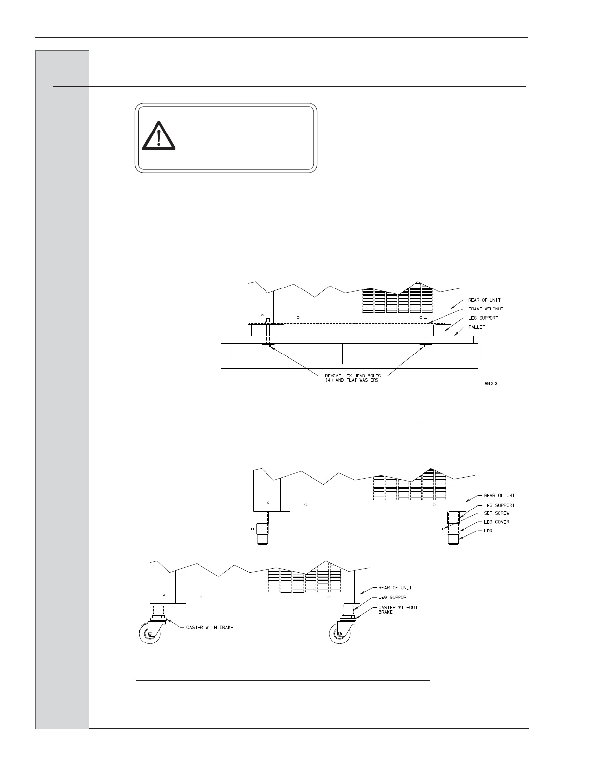
2.1 Uncrating and Inspection
Figure 2-1 Machine bolted to Shipping Base
CAUTION
Be sure to properly
support the machine when
removing bolts and
installing legs or casters.
When the unit is received and while the
carrier is still present, inspect the ship-
ping carton for any damage that may
have occurred in transit. If the
SHOCKWATCH
®
label indicates red
and/or the carton is broken, torn, or
punctured, note the damage on the
carrier’s freight bill and notify the
carrier’s local agent immediately.
1. Remove the carton from the
pallet, and move the machine as close
as possible to the permanent location.
2. Remove the shipping bolts on
the bottom of the freezer (figure 2-1)
and install either the legs or casters
(figure 2-2).
Figure 2-2 Installing Mounting Legs or Casters
NOTE: Screw casters
or legs all the way in
coupling, then adjust
to level side to side
with a 1/4” slope to
the front.

ELECTRO FREEZE Soft Serve Models SLX400, SLX400E, SLX500
184584
3
2.2 Installation
CAUTION
All materials and
connections must conform
to local requirements and
be in compliance with the
National Electrical Code
(NEC).
1. Thefreezerisdesignedforindoor
useandmustbeprotectedfromoutdoor
weatherconditions.
2. Wherecodespermit,Electro
Freezerecommendsthatthefloormodel
freezersbeinstalledoncastersandhave
flexiblewaterandelectricalconnections
foreasierserviceandcleaning.
3. Allmodelsarerequiredtobeopen
atthetop,haveaminimum6-inch(15.2
cm)rearclearanceand0inchesonthe
sidepanelsforadequateventilation.
Anythingblockingventilationofthefreezer
(includingconedispensers)willreducethe
efficiencyofthefreezer.
4. Aircooled model SLX500will
needanairdeflectoriftheunitistobe
placedagainstarearwall.The6”widex
21-7/8”longdeflectoristobemountedto
thelowerrearscrewson thebackpanelof
thefreezer.Failure to install the deflec-
tor will void warranty.
5. Water-cooledmodelsrequirea
3/8-inchMPTwaterinletandwaterwaste
connection. Theconnectionsarefoundon
thebottom,underthecompressormounting
area.Theyaretagged“WaterInlet”and
“WaterWaste.”Amanualshut-offvalve
shouldbeinstalled inthe waterinletlineat
thetimeofinstallation.Thewaterpressure
mustbebetween35-140psig(241-965
kPa)forproperoperation.
6. Placethefreezer inits final
location and adjust the legs or casters
so that it is level side-to-side and the
frontisapproximately1/4-inch lowerthan
thereartoallowproperdrainageofthe
freezingcylinder.
2.3 Electrical Requirements-Models SLX500 and SLX400
CAUTION
To prevent accidental
electrical shock, a positive
earth ground is required.
1. Always verify electrical specifi-
cations on the data plate (figure 3-1) of
each freezer. Data plate specifications
will always supersede the information in
this manual.
2. Supply voltage must be within +
10% of voltage indicated on the name-
plate. Also, on three-phase systems,
voltage between phases must be bal-
anced within 2%. (More than a 6 volt
difference between any two voltage
measurements at 208-230 volts indi-
cates a possible imbalance.) Request
your local power company to correct any
voltage problem.
3. An easily accessible main power
disconnect must be provided for all
poles of the wiring to the freezer.

4
184584
ELECTRO FREEZE Soft Serve Models SLX400, SLX400E, SLX500
CAUTION
Toprevent accidental
electricalshock, a positive
earthground isrequired.
1. Freezerrequiresonepowersupply.
Alwayscheckthedataplate forproperfuse
size,wireampacity,and electricalspecifi-
cations.
2. Refertothewiringdiagramprovided
forproperpowerconnections.
3. Electricalconnectionsfor
modelsSLX500and SLX400 aremadein
ajunctionbox. Facingthefrontofthe
freezer itislocatedbehindtheright side
paneltowardsthebackandbottomofthe
frame.
4. TheModel SLX400E issupplied
withacordan aNEMA6-20P plugthat
plugsintoa6-20Rreceptacle.SeeFigure
2-3.
2.5 Electrical Connections
4. Useaflexibleconnectionwhen
permissible.Copperwiresarerequiredfor
connectiontofreezer.Allmaterialsand
connectionsmustconformtolocalcodes
and/ortheNationalElectricalCode.
5. Forall3phasefreezers,beater
shaftrotationmustbeclockwiseasviewed
fromthefrontofthefreezer.
3. Supplyvoltagemustbewithin
±10%ofvoltageindicatedonthenameplate.
4. Aneasilyaccessiblemain power
disconnectmustbeprovidedforallpolesof
thewiringtothefreezer.
2.4 Electrical Requirements - Model SLX400E ONLY
CAUTION
Toprevent accidental
electricalshock, a
receptaclewith a positive
earthground isrequired.
1. Alwaysverifyelectricalspecifica-
tionsonthedataplate(figure4-1)ofeach
individualfreezer.Dataplatespecifications
willalwayssupersedetheinformationin
thismanual.
2. Thisfreezerrequiresaprotected20
amp220voltcircuit.Connectthefreezerto
acircuitseparatefrom anyotherelectrical
equipment.ThefreezerplugwillfitaNEMA
6-20Rreceptacle. Seefigure2-3.
Figure2-3 Plug

ELECTRO FREEZE Soft Serve Models SLX400, SLX400E, SLX500
184584
5
3.1 Particulars
3 Specifications
Width(in/cm) ...........................22-1/8/ 56.2
Height(in/cm).................... 60-11/16/154.15
Depth (in/cm) ........................ 30-1/8/76.52
SLX500 SLX400 SLX400E
Weight(lb/kg)................................. 539/244 ....................... 500/226 ...................... 475/215
CylinderCompressor.... 2HP/10500(BTU/hr) ... 1.3HP/6900(BTU/hr) .. 1.3HP/6900(BTU/hr)
1.9kw(Motor) ................1.3kw(Motor) ...............1.3kw(Motor)
3.2kw(Cooling) ............. 2.1kw(Cooling) ............ 2.1kw(Cooling)
HopperCompressor .... 1/10HP/500(BTU/hr) ... 1/10HP/500(BTU/hr) ... 1/10HP/500(BTU/hr)
BeaterMotor ........................ (2) 2HP/1.5 kw ............ (2)1HP/0.75kw .......... (2)1HP/0.75kw
Refrigerant-Cylinder...........................R-404a .......................... R-404a ..........................R-404a
Refrigerant-Hopper ............................R-134a ...........................R-134a ..........................R-134a
Charge Cylinder(lbs/kg)(A/C)) .......... 4.4 / 2.0 .......................... 4/1.81 ......................... 4/1.81
Charge-Cylinder(lbs/kg)(W/C) ........ 3.75 /1.7 ....................... 3.4 /1.54 ...................... 3.4 /1.54
Charge-Hopper (oz/kg) ........................7 / .2 ............................. 7 / .2 .............................7 / .2
Cooling....................................... AirorWater ................... AirorWater .................. AirorWater
Hopper(qt/ltr) ............................. (2) 16/ 15.1 ................... (2)12/ 11.4 .................. (2)12 /11.4
Cylinder(qt/ltr).............................(2)3.7/ 3.5 ....................(2)2.7 / 2.6 ...................(2) 2.7 / 2.6
A/C = AirCooled
W/C = WaterCooled

6
184584
ELECTRO FREEZE Soft Serve Models SLX400, SLX400E, SLX500
Write in
Reference Informa-
tion HERE!
3.3 Reference Information
Fillinthefollowinginformationassoonas
youreceiveyourElectroFreezeSLX400
series or SLX500freezer.(Theitem
numbers—encircled,below —correspond
tothecalloutnumbersinfigure3-1.)
1 ModelNumber:_________________
2 SerialNumber:__________________
3 Electrical Spec: Voltage ________
Phase _______ Hertz _________
4 Max.FuseSize:__________________
5 Min.CircuitAmpacity___________
3.2 Data Plate
The data plate provides important
information that the operator should
record and have available for parts
ordering, warranty inquiries and service
requests.
Figure 3-1

ELECTRO FREEZE Soft Serve Models SLX400, SLX400E, SLX500
184584
7
Figure3-2 ElectroFreezeSLXSeries
ThedimensionsoftheSLXSeriesfreezers
areprovidedinfigure3-2below.
3.5 Dimensions
3.4 Installation Date
Fillinthedateofinstallation,andthename, address,andphonenumberoftheinstallerin
thespaceprovidedbelow.Thisinformationwillbeneededwhenorderingpartsorservicefor
thefreezer.
Date of installation: ____________________________________
Installed by: ____________________________________
Address: ____________________________________
____________________________________
Phone: ____________________________________

8
184584
ELECTRO FREEZE Soft Serve Models SLX400, SLX400E, SLX500
4 Virtual Quality Management System (VQM)
Terminology
AmpControlBoard:........... Board is located in the main contactor box responsible for
monitoringthe beater motor amperage and communicating
that value to the main P.C. Board.
BeaterRun:....................... This D.O.B. timer used to delay the beater motor after the
refrigerationshuts down. Beater Run Range: 0 to 10 seconds
DemandRun Comp: .......... The D.O.B. timer used to delay the compressor when product
is being drawn. Demand Run Comp. Range: 0 to 12 seconds
Dual Hyst: ......................... The differential usedwhen productis being drawnout ofthe
centerspigot or when both side spigots have been drawn
simultaneously. Dual Hysteresis range: 7 to 20°F
Hysteresis (Hyst): ............. Symbolizes the differential setting. Hysteresis range: 7 to
20°F i.e. if your cut in is at 18°F and your Hysteresis is at
10°F your unit will cut out at 8°F
IdleRun Comp: ................. Delay on break (D.O.B.) timer used for the compressor when
the unit is in idle mode/no product being drawn. Idle Run
Comp. Range: 0 to 12 seconds
Idle: ................................... When the unit is cycling on temperature and no product is
beingdispensed
Lock outs: ......................... Allows the function of a specific feature/button to be
temporarily disabled to deter unnecessary usage of that
feature.
Main P.C. Board: ............... Main Control board for the unit, housed behind the trim strip
panel. This board has many connectors on it and is
responsiblefor the main operations of the unit.
MembraneSwitch: ............ The black Electro Freeze decal visible on the front of the unit,
whichhouses the hidden operator, technician, soft, and hard
keys used to navigate the menus
Single Hyst: ...................... The differential used when product is being drawn out of one
barrel. Single Hysteresis range: 7 to 20°F
Slope/DemandSlope:........ Utilizes a function within the system to watch the
temperature change as the unit freezes a barrel. If utilizing
the slope feature and the unit sees a lack of temperature
change during freeze down, the unit will cycle off. This will
preventa freeze up condition due to a long run time. Demand
Slope range: 0 to -0.2

ELECTRO FREEZE Soft Serve Models SLX400, SLX400E, SLX500
184584
9
Temp. Comp.:.................... Temperaturecomparison,utilized when the slope feature is
turned on. It prevents the system from seeing the slope
temperaturecurve until a determined temperature is reached.
Once that temperature has been reached then the system
will examine the curve and shut down if necessary.
Temp. Comp. Range: -10 to 15°F
TemperatureOffset: ........... A function that allows temperature adjustment to the
operator.Adjustablefrom1-9 and 5 being neutral/no change,
Lowerthan5=colderandgreaterthan5=warmer
U.I./User Interface: ........... The board that lies directly behind the membrane switch on
the front panel. This board houses the LED screen that
displays the menus and operations. The membrane switch is
connected to this board via a ribbon cable. This board also
has its own software.
4 Virtual Quality Management System (VQM)
Terminology (continued)

10
184584
ELECTRO FREEZE Soft Serve Models SLX400, SLX400E, SLX500
5 Part Names and Functions
6 ROD - PLUNGER
Starts the freezer when dispensing.
Must be in place for proper
operation.
7 PIN - HANDLE
Secures handle to the head.
8 KNOB - HAND
Secures the head to the freezing
cylinder.
9 HANDLE - DISPENSE - SIDE
Opens and closes the plunger to
start and stop the flow of product
from the freezer.
10 HANDLE - DISPENSING - CENTER
Opens and closes the plunger to
start and stop the flow of swirl
product from the freezer.
11 NOZZLE - SERRATED
Forms the frozen product as it is
dispensed.
1 HEAD - DISPENSE
Encloses the freezing cylinder and
provides an opening for product to be
dispensed.
2 O-RINGS - HEAD
Seals the head to the freezing
cylinder. Must be lubricated.
3 PLUNGERS - DISPENSE - SIDE
Seals the product opening in the head
when closed. Allows product to flow
when open.
4 O-RINGS - PLUNGER
Seals the plunger in the head. Must be
lubricated to seal and slide freely.
5 PLUNGER - DISPENSE - CENTER
Seals the product opening in the head
when closed. Combines ice cream
from both cylinders to form swirl
cones.
Thefollowingdescriptionsrefertofigure5-1.Thenumberprecedingthepartnamecorre-
spondstothenumberinthefigure.
Figure5-1 HeadAssembly

ELECTRO FREEZE Soft Serve Models SLX400, SLX400E, SLX500
184584
11
5 Part Names and Functions (continued)
Figure5-2 BeaterShaftAssemblies
Thefollowingdescriptionsrefertofigure5-2.Thenumberprecedingthepartnamecorre-
spondstothenumberinthefigure.
SEAL-BEATERSHAFT
Sealstheopeningbetweenthe
freezingcylinderandthebeatershaft.
Consistsofthefollowing:
4 SEAL-BEATERSHAFT
5 WASHER-DOUBLESHAFT
SEAL
1 BAR-BREAKER
Keepsproductblendedinthecenter
ofthebeatershaft.
2 SHAFT-ASSY.BEATER
Rotatesinthefreezingcylinder,
blendingairandmix.Ejectsproduct
whendispensingplungerisopened.
3 BLADE-SCRAPER
Scrapesthefrozenproductfromthe
freezingcylinder.

12
184584
ELECTRO FREEZE Soft Serve Models SLX400, SLX400E, SLX500
5 Part Names and Functions (continued)
Figure5-3 MixFeedTubeAssembly
1 TUBE - MIX FEED.
Metersthecorrectamountofmixand
airintothefreezingcylinderfromthe
hopper.
2 REGULATOR.
Providesadjustmentonmixfeedrate
andapositiveshut-offofmixflowto
thefreezingcylinder.
3 O-RING-TUBE.
Sealstheopeningbetweenthehopper
andmixfeedtube.(O-ringsdonot
needlubrication.)
Thefollowingdescriptionsrefertofigure5-3.Thenumberprecedingthepartnamecorre-
spondstothenumberinthefigure.
REGULATOR
ORING
MIXFEED TUBE
This manual suits for next models
2
Table of contents
Popular Commercial Food Equipment manuals by other brands


Vollrath
Vollrath STOELTING Flavor Burst STL-80BLD Operator's manual

True
True TDB-24-48-1-G-1-HC installation manual

Mono
Mono Ecotouch Operation and maintenance manual

Ruhle
Ruhle IR 56 Quick installation guide

Diamond
Diamond G77/PL4T-N installation instructions

Victor
Victor STADIA HC31SSLGH5 operating manual