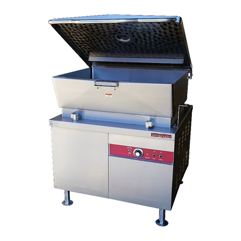
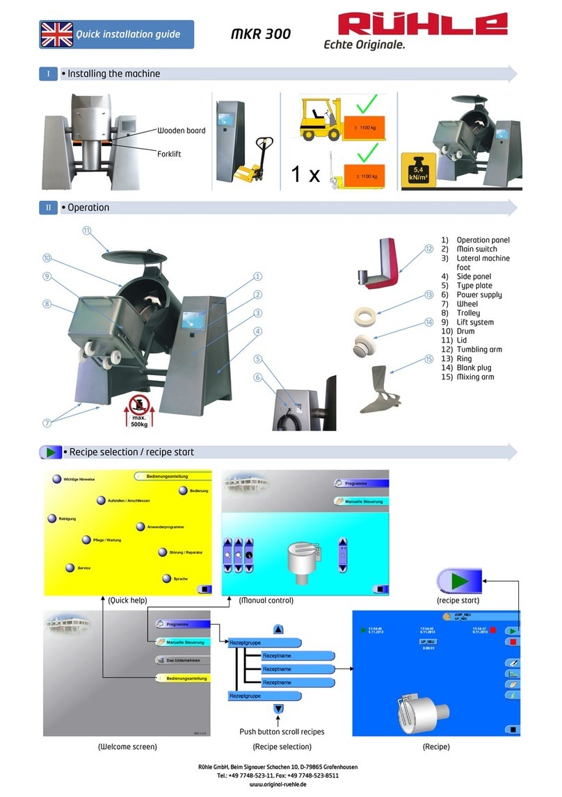
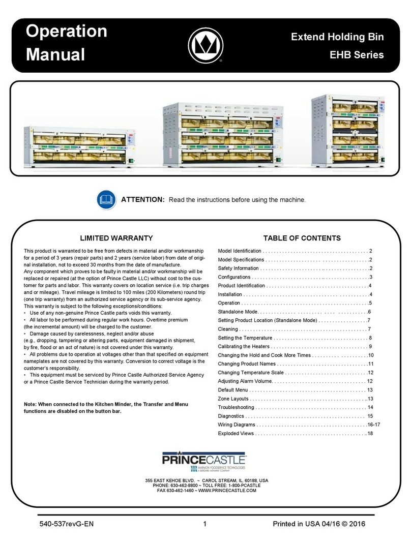
THERMODYNE 1200 G User manual

SERVICE
MANUAL
(05-23)
Thermodyne Foodservice Products, Inc.
4418 New Haven Avenue 1-800-526-9182
Fort Wayne, IN 46803 www.tdyne.com
ADDFLU ID
Out 1
Out 2
ADDFLU ID
Out 1
Out 2
ADDFLU ID
Out 1
Out 2
MODELS
1200 G
1300 G
1900 G
1200 DW
1900 DW
2100 DW
3000 P
6000 P
For additional information on Thermodyne Foodservice Products, Inc.,
or to locate an authorized parts and service provider in your area,
visit our website at www.tdyne.com.
Please visit our website to Register your Thermodyne unit. Registration ensures that you
get up-to-date warranty and product information, along with fast and convenient service.
http://www.tdyne.com/register.aspx

— 2 —
ELECTRICAL WARNINGS
THIS MANUAL HAS BEEN PREPARED FOR PERSONNEL QUALIFIED TO INSTALL ELECTRICAL
EQUIPMENT, WHO SHOULD PERFORM THE INITIAL FIELD STARTUP AND ADJUSTMENTS OF
THE EQUIPMENT COVERED BY THIS MANUAL.
READ THIS MANUAL THOROUGHLY BEFORE OPERATING, INSTALLING OR PERFORMING
MAINTENANCE ON THE EQUIPMENT.
WARNING: Failure to follow all the instructions in this manual can cause property
damage, injury or death.
WARNING: Improper installation, adjustment, alteration, service or maintenance can cause
property damage, injury or death.
WARNING: Electrical connections should be performed only by a certied professional.
WARNING: Electrical and grounding connections must comply with the applicable
portions of the National Electric Code and/or all local electric codes. Failure to comply with this
procedure can cause property damage, injury or death.
WARNING: Before connecting the unit to the electrical supply, verify that the electrical and
grounding connections comply with the applicable portions of the National Electric Code and/or
other local electrical codes. Failure to comply with this procedure can cause property damage,
injury or death.
WARNING: Before connecting the unit to the electrical supply, verify that the electrical
connection agrees with the specications on the data plate. Failure to comply with this
procedure can cause property damage, injury or death.
WARNING: UL73 grounding instructions: This appliance must be connected to a
grounded, metal, permanent wiring system. Or an equipment-grounding conductor must be run
with the circuit conductors and connected to the equipment-grounding terminal or lead on the
appliance. Failure to comply with this procedure can cause property damage, injury or death.
WARNING: Appliances equipped with a exible electric supply cord, are provided with
a three-prong grounding plug. It is imperative that this plug be connected into a properly
grounded three-prong receptacle. Failure to comply with this procedure can cause property
damage, injury or death.
WARNING: If the receptacle is not the proper grounding type, contact an electrician. Do
not remove the grounding prong from the plug. Failure to comply with this procedure can cause
property damage, injury or death.

— 3 —
WARNING: Before performing any service that involves electrical connection or
disconnection and/or exposure to electrical components, always perform the Electrical
LOCKOUT/TAGOUT Procedure. Disconnect all circuits. Failure to comply with this procedure can
cause property damage, injury or death.
WARNING: Before removing any sheet metal panels, always perform the Electrical
LOCKOUT/TAGOUT Procedure. Be sure all circuits are disconnected. Failure to comply with this
procedure can cause property damage, injury or death.
WARNING: Do not operate this equipment without properly placing and securing all
covers and access panels. Failure to comply with this procedure can cause property damage,
injury or death.
WARNING: Do not use or store gasoline or other ammable vapors or liquids in the
vicinity of this or any other appliance. Failure to comply can cause property damage, injury or
death.
WARNING: In the event of a power failure, do not attempt to operate this appliance. Failure
to comply can cause property damage, injury or death.

— 4 —
TABLE OF CONTENTS
ELECTRICAL LOCKOUT/TAGOUT PROCEDURE .......................................................................................... 5
COVERS AND PANELS ................................................................................................................................... 6
Top Fill Cover ............................................................................................................................................. 6
Power Head Lid.......................................................................................................................................... 6
Side Panels ................................................................................................................................................ 7
Doors.......................................................................................................................................................... 7
COMPONENT LOCATOR................................................................................................................................. 8
Power Head Components .......................................................................................................................... 8
Delivery Manifold Components .................................................................................................................. 9
Return Manifold Components .................................................................................................................. 10
COMPONENT REMOVAL AND REPLACEMENT...........................................................................................11
ELECTRICAL COMPONENTS .................................................................................................................11
Power Toggle Switch...........................................................................................................................11
Add Fluid Light....................................................................................................................................11
Temperature Controller ...................................................................................................................... 12
Cooling Fan ....................................................................................................................................... 13
Power Cord ........................................................................................................................................ 14
POWER BOARD COMPONENTS ........................................................................................................... 14
Solid State Relay ............................................................................................................................... 14
Float Board ........................................................................................................................................ 15
PLUMBING COMPONENTS ................................................................................................................... 16
B&G Pump......................................................................................................................................... 16
Teon Hoses...................................................................................................................................... 17
Fluid Level Probes ............................................................................................................................. 18
Snap Disc .......................................................................................................................................... 19
THERMOCOUPLE................................................................................................................................... 20
HEAT ELEMENTS.................................................................................................................................... 21
MAINTENANCE PROCEDURES ................................................................................................................... 24
Temperature Controller Set Up Procedures.............................................................................................. 24
Keypad Operation .................................................................................................................................... 24
Set Up ...................................................................................................................................................... 24
Changing the Heat Transfer Fluid............................................................................................................. 24
Door Adjustment....................................................................................................................................... 26
Stainless Steel Care................................................................................................................................. 27
TROUBLESHOOTING.................................................................................................................................... 28
WIRING SCHEMATICS .................................................................................................................................. 29
WARRANTY ................................................................................................................................................... 31
HEAT TRANSFER FLUID MSDS ................................................................................................................... 31

— 5 —
ELECTRICAL LOCKOUT/TAGOUT PROCEDURE
WARNING
Before performing any service that involves
electrical connection or disconnection
and/or exposure to electrical components,
always follow the Electrical LOCKOUT/
TAGOUT Procedure. Disconnect all circuits.
Failure to comply can cause property
damage, injury or death.
The Electrical LOCKOUT/TAGOUT Procedure is
used to protect personnel working on an electrical
appliance. Before performing any maintenance
or service that requires exposure to electrical
components, follow these steps:
1. In electrical box, place appliance circuit breaker
into OFF position.
2. Place a lock or other device on electrical box
cover to prevent someone from placing circuit
breaker ON.
3. Place a tag on electrical box cover to indicate
that appliance has been disconnected for
service and power should not be restored until
tag is removed by maintenance personnel.
4. Disconnect appliance power cord from
electrical outlet.
5. Place a tag on the cord to indicate that unit
has been disconnected for service and power
should not be restored until tag is removed by
maintenance personnel.
MODEL
GALLONS LITERS
PER
SHELF
(OZ)
125 OC 1. 5 3.78 14
200 NDNL 1.75 6.62 6
200 CT 1.75 6.62 6
250 OC 1.65 6.62 20
250 PNDT 2.1 7.95 6
BW3 1.65 6.25 6
BW4 1. 7 6.44 6
300 NDNL 1.91 7.23 6
300 CT 1.91 7.23 6
700 NDNL 2.25 8.52 14
700 CT 2.25 8.52 14
950 NDNL 2.16 8.18 20
300 OC 2.24 8.48 14
FLUID CAPACITIES (STANDARD SHELF CONFIGURATION)
MODEL
GALLONS LITERS
PER
SHELF
(OZ)
1200 G 2.22 8.40 13
1200 DW 2.3 8.71 14
1300 G 2.32 8.78 13
1600 NDNL 2.1 7.95 6
1900 G 3.02 11.43 13
1900 DW 3.06 11.58 14
2100 DW 3.59 13.59 20
6000 P 4.95 18.74 23.8
700 DP 2.25 8.52 14
1500 DP 3.01 11.39 14
742 HW 2.45 9.27 14
744 HW 3 11.36 28
1600 HZ 2.5 9.46 Top-14;
Bottom-6

— 6 —
COVERS AND PANELS
TOP FILL COVER
TheTop Fill Cover provides access to the Reservoir
Tank Cap without the requirement to remove the
entire Power Head Lid.Remove the cover to access
the Reservoir Tank Cap when the Add Fluid Light
is illuminated.
1. Place the Power Toggle Switch to the OFF
position.
2. Remove the Philips screws securing the Top
Fill Cover.
3. Remove the Top Fill Cover.
4. Reverse the procedure to reinstall the Top Fill
Cover.
Top Fill Cover
ADD FLUID
Out1
Out2
Figure 1: Top Fill Cover
POWER HEAD LID
WARNING
Before removing any sheet metal panels or
servicing this equipment, always perform
the Electrical LOCKOUT/TAGOUT Procedure.
Be sure all circuits are disconnected. Failure
to comply with this procedure can cause
property damage, injury or death.
Removing the Power Head Lid provides access to
all of the components of the Power HeadAssembly.
1. Perform the ELECTRICAL LOCKOUT/
TAGOUT procedure.
2. Remove the Philips screws securing the Power
Head Lid.
3. Remove the Power Head Lid.
4. Reverse the procedure to reinstall the Power
Head Lid.
Power Head Lid
Figure 2: Power Head Lid

— 7 —
SIDE PANELS
WARNING
Before removing any sheet metal panels or
servicing this equipment, always perform
the Electrical LOCKOUT/TAGOUT Procedure.
Be sure all circuits are disconnected. Failure
to comply with this procedure can cause
property damage, injury or death.
The Side Panels provide access to the Fluid
Delivery and Fluid Return systems.
1. Perform the ELECTRICAL LOCKOUT/
TAGOUT procedure.
2. Using a regular screwdriver turn the Quarter
Turn Post counterclockwise until it unlatches.
3. Repeat until all Quarter Turn Posts are loose.
4. Lift the Side Panel up and away from the unit.
5. Reverse the procedure to reinstall the Side
Panel.
Side
Panel
ADD FLUID
Out1
Out2
Figure 3: Side Panel Removal
DOORS
All DW, G & P models are supplied with doors
that lift off hinges. To remove the doors, open the
door slightly and lift it straight up and off the hinge.

— 8 —
COMPONENT LOCATOR
POWER HEAD COMPONENTS
23456789
10 11 12
1
3
4
15
5
11
10
9
6
7
17 1412 13 15 16 1 2
ADD FLUID
8
Figure 4: Power Head Components
1. Cooling Fan
2. B&G Pump
3. Reservoir Fill Cap
4. Reservoir Assembly
5. Contactor
6. Lighted Power Toggle Switch
7. Add Fluid Light
8. Temperature Controller
9. Solid State Relay
10. 120VAC Float Board
11. Neutral Lug
12. Heater Elements
13. Snap Disc
14. 16 PSI Pressure Cap
15. Fluid Level Probes
16. Thermocouple
17. Heater Tank Assembly

— 9 —
DELIVERY MANIFOLD COMPONENTS
73
4
2
1
6 5
Figure 5: Delivery Manifold Components
1. Delivery Line
2. Teon Washer
3. Shelf Plug
4. Power Cord
5. Delivery Manifold Assembly
6. Short Teon Hose
7. Shelf Elbow

— 10 —
RETURN MANIFOLD COMPONENTS
8
2
3
4
1
7 6 5
Figure 6: Return Manifold Components
1. Overow Tube
2. Shelf Plug
3. Teon Washer
4. Drain Tube
5. Drain Tube ON/OFF Valve
6. Return Manifold
7. Long Teon Hose
8. Shelf Elbow

— 11 —
COMPONENT REMOVAL AND REPLACEMENT
ELECTRICAL COMPONENTS
WARNING
Before removing any sheet metal panels or
servicing this equipment, always perform
the Electrical LOCKOUT/TAGOUT Procedure.
Be sure all circuits are disconnected. Failure
to comply with this procedure can cause
property damage, injury or death.
WARNING
Certain components may be hot if the
unit was in operation prior to performing
a procedure. Allow the unit to cool before
beginning work.
POWER TOGGLE SWITCH
1. Perform the ELECTRICAL LOCKOUT/
TAGOUT procedure.
2. Perform the POWER HEAD LID removal
procedure.
3. Tag and disconnect the wires connected to
the Power Toggle Switch.
4. Squeeze the spring tabs that hold the switch
in place and push the switch through the front
of the unit.
Note: If the switch being removed is damaged,
it may be easier to break the spring tabs
off of the switch rather than attempting to
squeeze the spring tabs. If this method
is used, remember to remove the broken
tabs from the inside of the Power Head.
Spring
Tab
Power
Toggle
Switch
Figure 7: Power Toggle Switch Removal
CAUTION: Always use pliers when removing
electrical wire connectors. Do NOT pull on
the wires to remove the connectors.
5. Insert the new switch through the front of the
unit ensuring that the tabs lock into place.
6. Refer to thetagsorwiring schematictoreconnect
the wires to the new Power Toggle Switch.
7. Restore power to the unit and check the Power
Toggle Switch for proper operation.
8. Remove power from the unit.
9. Reverse the POWER HEAD LID removal
procedure to reinstall the Power Head Lid.
10. Restore power to the unit and verify proper
operation.
ADD FLUID LIGHT
WARNING
Before removing any sheet metal panels or
servicing this equipment, always perform
the Electrical LOCKOUT/TAGOUT Procedure.
Be sure all circuits are disconnected. Failure
to comply with this procedure can cause
property damage, injury or death.

— 12 —
WARNING
Certain components may be hot if the
unit was in operation prior to performing
a procedure. Allow the unit to cool before
beginning work.
1. Perform the ELECTRICAL LOCKOUT/
TAGOUT procedure.
2. Perform the POWER HEAD LID removal
procedure.
3. Pull the light socket out from the Add Fluid
Light cover.
4. Tag and disconnect the two wire connectors.
Power
Toggle
Switch
Spring
Tabs
Add Fluid
Light
Light
Socket
Figure 8: Add Fluid Light Removal
5. Reverse the procedure to reinstall the Add
Fluid Light.
6. Restore power to the unit and check the Add
Fluid Light for proper operation.
Note: The Add Fluid Light will not illuminate if
the Heat Transfer Fluid level is sufficient.
Drain uid as necessary in order to test
for proper light operation. Refer to the
CHANGING HEAT TRANSFER FLUID
procedure for draining and adding Heat
Transfer Fluid.
7. Remove power from the unit.
8. Reverse the POWER HEAD LID removal
procedure to reinstall the Power Head Lid.
9.
Restore power to the unit and verify proper
operation.
TEMPERATURE CONTROLLER
The Temperature Controller consists of two
parts: the Controller Main Board (wire harness
terminals) and the Display/Pushbutton Board.
These two boards are connected by a multi-
conductor ribbon cable.
Display/ Pushbutton
MainBoard
Figure 9: Temperature Controller
1. Follow the LOCKOUT/TAGOUT procedure
using the procedures provided in the Lockout/
Tagout Procedures section of this manual.
2. Remove the Power Head Lid following the
instructions provided in the Panels and Covers
section of this manual.
3. The TBC-41 Controller is very easy to remove.
There are four screws and spacers apiece
holding the display and power boards. They
are different lengths: the spacers used with
the power board are 1/2" (12.7mm) long; the
spacers used with the display board are 5/16"
(8mm) long.

— 13 —
Springs (4)
1/2"(12.7mm)
Spacers(4)
Figure 10: Temperature Controller Removal
4. Restore the power and check the controller
for proper operation.
5. Remove the unit from its power source and
reattach the Power Head Lid.
6. Restore power to the unit and ensure it is
operating correctly.
NOTICE: The new Temperature Controller
may require set up procedures. Refer to the
Temperature Controller Set Up Procedures
section of this manual for set up procedures.
WARNING
Before removing any sheet metal panels or
servicing this equipment, always perform
the Electrical LOCKOUT/TAGOUT Procedure.
Be sure all circuits are disconnected. Failure
to comply with this procedure can cause
property damage, injury or death.
WARNING
Certain components may be hot if the
unit was in operation prior to performing
a procedure. Allow the unit to cool before
beginning work.
COOLING FAN
WARNING
Before removing any sheet metal panels or
servicing this equipment, always perform
the Electrical LOCKOUT/TAGOUT Procedure.
Be sure all circuits are disconnected. Failure
to comply with this procedure can cause
property damage, injury or death.
WARNING
Certain components may be hot if the
unit was in operation prior to performing
a procedure. Allow the unit to cool before
beginning work.
1. Perform the ELECTRICAL LOCKOUT/
TAGOUT procedure.
2. Perform the POWER HEAD LID removal
procedure.
3. Unplug the leads from the fan.
4. Remove the four screws securing the fan to
the Power Head.
Figure 11: Cooling Fan Removal
5. Reverse this procedure to install the new
Cooling Fan.
6. Restore power to the unit and ensure it is
operating correctly.

— 14 —
POWER CORD
WARNING
Before removing any sheet metal panels or
servicing this equipment, always perform
the Electrical LOCKOUT/TAGOUT Procedure.
Be sure all circuits are disconnected. Failure
to comply with this procedure can cause
property damage, injury or death.
WARNING
Certain components may be hot if the
unit was in operation prior to performing
a procedure. Allow the unit to cool before
beginning work.
1. Perform the ELECTRICAL LOCKOUT/
TAGOUT procedure.
2. Perform the POWER HEAD LID removal
procedure.
3. Disconnect the Power Cord from the Contactor
and remove the ground screw securing the
green ground wire to the unit frame.
4. Refer to the wiring schematic to connect the
new power cord.
5. Restore power to the unit.
6. Verify the unit is working properly.
7. Remove power from the unit.
8. Reverse the POWER HEAD LID removal
procedure to reinstall the Power Head Lid.
9. Restore power to the unit and ensure it is
operating correctly.
POWER BOARD COMPONENTS
The Power Board Components include the Solid
State Relay, Contactor, Float Board and the Neutral
Lug.Under normal circumstances it should not be
necessary to replace either the Contactor or the
Neutral Lug.
Note: The Power Board is mounted on plastic
risers that allow for air to ow on the
underside of the board.It is not necessary
to remove the Power Board when replacing
one of its components; however it may
be necessary to loosen the screws that
secure the Power Board to the unit.Loosen
but do not remove the screws as they hold
the plastic risers in place.
Neutral
Lug
Power
Board
Contactor
120VAC
Float
Board
Solid State
Relay
Figure 12: Power Board Components
Solid State Relay
WARNING
Before removing any sheet metal panels or
servicing this equipment, always perform
the Electrical LOCKOUT/TAGOUT Procedure.
Be sure all circuits are disconnected. Failure
to comply with this procedure can cause
property damage, injury or death.
WARNING
Certain components may be hot if the
unit was in operation prior to performing
a procedure. Allow the unit to cool before
beginning work.
1. Perform the ELECTRICAL LOCKOUT/
TAGOUT procedure.
2. Perform the POWER HEAD LID removal
procedure.
3. Tag and disconnect the wires to the Solid State
Relay.
4. Remove the Solid State Relay by removing the
two screws securing it to the Power Board.
It may be necessary to loosen the screws
securing the Power Board to gain access to
the screws at the front of the Solid state Relay.

— 15 —
Relay
Mounting
Screws
Plastic
Riser
Power Board
Mounting Screws
Figure 13: Solid State Relay Removal
5. Install the new Solid State Relay.
6. Reattach the screws securing the Power Board
to the unit.
7. Refer to the tags or the wiring schematic to
reconnect the wires to the new Solid State
Relay.
8. Restore power to the unit and verify operation.
9. Reverse the POWER HEAD LID removal
procedure to reinstall the Power Head Lid.
10.
Restore power to the unit and ensure it is
operating correctly.
Float Board
WARNING
Before removing any sheet metal panels or
servicing this equipment, always perform
the Electrical LOCKOUT/TAGOUT Procedure.
Be sure all circuits are disconnected. Failure
to comply with this procedure can cause
property damage, injury or death.
WARNING
Certain components may be hot if the
unit was in operation prior to performing
a procedure. Allow the unit to cool before
beginning work.
1. Perform the ELECTRICAL LOCKOUT/
TAGOUT procedure.
2. Perform the POWER HEAD LID removal
procedure.
3. Tag and disconnect the wires attached to the
Float Board.
Note: It is NOT necessary to loosen the Power
Board screws to gain access to the Float
Board.
4. Remove the screws and plastic risers securing
the Float Board to the Power Board and lift the
Float Board out of the unit.
Float Board
Mounting
Screws
Plastic
Riser
Figure 14: Float Board Removal
5. Install the new Float Board making sure a
plastic riser is attached to each screw.
6. Refer to the tags or the wiring schematic to
reconnect the wires to the new Float Board.
7. Restore power to the unit and check it for
proper operation.
8. Remove power from the unit.
9. Reverse the POWER HEAD LID removal
procedure to reinstall the Power Head Lid.
10.
Restore power to the unit and ensure it is
operating correctly.

— 16 —
PLUMBING COMPONENTS
B&G Pump
WARNING
Before removing any sheet metal panels or
servicing this equipment, always perform
the Electrical LOCKOUT/TAGOUT Procedure.
Be sure all circuits are disconnected. Failure
to comply with this procedure can cause
property damage, injury or death.
WARNING
Certain components may be hot if the
unit was in operation prior to performing
a procedure. Allow the unit to cool before
beginning work.
WARNING
Before servicing the plumbing system the heat
transfer uid must be drained from the system.
Additional tools required for this procedure:
• 1-1/16 Wrench
• 1-3/8 Wrench
• 7/16 Wrench
1. Perform the ELECTRICAL LOCKOUT/
TAGOUT procedure.
2. Perform the POWER HEAD LID removal
procedure.
3. Perform the SIDE PANEL removal procedure
to remove the left side panel.
4. Locate the Drain Tube and place it into an
empty pan.
Drain Valve
Drain
Tube
Figure 15: Drain Tube and Drain Valve
Location
5. Remove both the Heater Tank Pressure and
the Reservoir Caps.
Heater Tank
Cap
Reservoir
Cap
B&G Pump
Gaskets
Pump
Bracket
Delivery
Hose
Fitting
Pump
Unions
Figure 16: B&G Pump Removal
6. Open the Drain Valve to drain the Heat
Transfer Fluid.
7. Discard the drained uid. Refer to the HEAT
TRANSFER FLUID MATERIAL SAFETY DATA
SHEET provided at the end of this manual for
proper disposal of the uid.
8. Tag and disconnect the B&G pump wires.
9. Using the 1-1/16 wrench, remove the Delivery
Line.
10.
Using the 1-3/8 wrench, unscrew the unions
on both sides of the pump.
11.
Using the 7/16 wrench, remove the u-clamp
securing the pump to the Pump Bracket and
remove the pump.
12.
Place the new pump into position.
13.
Loosely connect the u-clamp.
14.
Ensure NEW gaskets are in place at both unions
and tighten the unions using the 1-3/8 wrench.
15.
Tighten the 7/16 nuts on the u-clamp.
16.
Reconnect the Delivery Line.
1 7.
Refer to the tags or wiring schematic to
reconnect the pump wires.

— 17 —
18.
Close the Drain Valve.
19.
Restore power to the unit.
20.
Fill the Heater Tank with FRESH Heat Transfer
Fluid and replace Heater Tank Pressure Cap.
2 1.
Fill the Reservoir Tank until the Add Fluid Light
goes out and replace Reservoir Tank Cap.
22.
Ensure there are no leaks at the pump unions
or Delivery Line ttings.
23.
Remove power from the unit.
24.
Reverse the POWER HEAD LID removal
procedure to reinstall the Power Head Lid.
25.
Reverse the SIDE PANEL removal procedure
to reinstall the panel.
26.
Restore the power to the unit and check it for
proper operation. It may be necessary to add
additional uid after the unit has operated for
several minutes.
Teon Hoses
WARNING
Before removing any sheet metal panels or
servicing this equipment, always perform
the Electrical LOCKOUT/TAGOUT Procedure.
Be sure all circuits are disconnected. Failure
to comply with this procedure can cause
property damage, injury or death.
WARNING
Certain components may be hot if the
unit was in operation prior to performing
a procedure. Allow the unit to cool before
beginning work.
WARNING
Before servicing the plumbing system the
heat transfer uid must be drained from
the system.
Under normal operating circumstances it
should not be necessary to replace a hose.
Should a hose become damaged or begin
leaking it must be replaced. There are two
sets of Teflon Hoses installed on each unit.
The short Teflon Hoses are located on the
delivery side (left side) of the unit. The long
Teflon Hoses are located on the return side
(right side) of the unit. Both sets of hoses are
replaced in the following manner:
1. Perform the ELECTRICAL LOCKOUT/
TAGOUT procedure.
2. Perform the POWER HEAD LID removal
procedure.
3. Perform the SIDE PANEL removal
procedure to remove the applicable side
panel.
4. Locate the Drain Tube and place it into an
empty pan.
5. Remove Heater Tank Cap and Reservoir
Cap.
6. Open the Drain Valve to drain the Heat
Transfer Fluid.
7. Discard the drained fluid. Refer to the
Heat Transfer Fluid Material Safety Data
Sheet provided at the end of this manual
for proper disposal of the fluid.
8. Using an open end 3/4 wrench remove the
hose from the Shelf Elbow side first.
9. Using an open end 7/16 wrench remove
the hose from the manifold.
Shelf
Elbow
Manifold
Teflon Tube Drain Tube
Figure 17: Return Side of Unit

— 18 —
Shelf
Elbow
Manifold
Teflon Tube
Figure 18: Delivery Side of Unit
10. Attach the replacement Teon Hose to the
manifold rst, then attach the other end to the
Shelf Elbow using the appropriate wrenches.
11. Close the Drain Valve.
12. Restore power to the unit.
13. Fill the HeaterTank with FRESH HeatTransfer
Fluid and replace Heater Tank Pressure Cap.
14. Fill the ReservoirTank until theAdd Fluid Light
goes out and replace the ReservoirTank Cap.
15. Ensure there are no leaks around the ttings
of the new hose.
16. Remove power from the unit.
17. Reverse the POWER HEAD LID removal
procedure to reinstall the Power Head Lid.
18. Reverse the SIDE PANEL removal procedure
to reinstall the applicable side panel.
19. Restore power to the unit and check it for
proper operation. It may be necessary to add
additional uid after the unit has operated for
several minutes.
20. After the unit has operated for several minutes
remove the Side Panel where the hose was
replaced and ensure that it is not leaking.
Tighten as necessary.
21. Reattach the removed Side Panel.
Fluid Level Probes
WARNING
Before removing any sheet metal panels or
servicing this equipment, always perform
the Electrical LOCKOUT/TAGOUT Procedure.
Be sure all circuits are disconnected. Failure
to comply with this
procedure can cause
property damage, injury or death.
WARNING
Certain components may be hot if the
unit was in operation prior to performing
a procedure. Allow the unit to cool before
beginning work.
WARNING
Before servicing the plumbing system the
heat transfer uid must be drained from
the system.
There are two Fluid Level Probes.One is installed
in the Heater Tank and the other is installed in
the Reservoir Tank. Before changing either of the
probes, check the uid levels in the Heater and
the Reservoir Tanks. Also, check the electrical
connection to the probes. The probes should test
as open with a continuity test when the tanks are
lled with uid.With an empty tank the probe should
test as closed during a continuity test.
1. Perform the ELECTRICAL LOCKOUT/
TAGOUT procedure.
2. Perform the POWER HEAD LID removal
procedure.
3. Perform the SIDE PANEL removal procedure
to remove the left side panel.
4. Locate the Drain Tube and place it into an
empty pan.
5. Remove the HeaterTank Cap and the Reservoir
Cap.
6. Open the DrainValve to drain the HeatTransfer
Fluid.
7. Discard the drained uid. Refer to the Heat
Transfer Fluid Material Safety Data Sheet

— 19 —
provided at the end of this manual for proper
disposal of the uid.
Fluid
Sensor
Probes
Figure 19: Fluid Level Probe Removal
8. Disconnect the Fluid Level Probe lead.
9. Remove the defective probe.
10. Install the new probe.
11. Reconnect the probe lead.
12. Restore power to the unit.
13. Close the uid Drain Valve.
14. Fill the Heater Tank and Reservoir Tank with
uid until the Low Fluid Light goes out.
15. Ensure that are no leaks around the newly
installed probe, tighten as needed.
16. Remove power from the unit.
17. Reverse the POWER HEAD LID removal
procedure to reinstall the Power Head Lid.
18. Reverse the SIDE PANEL removal procedure
to reinstall the panel.
19. Restore power to the unit and verify the unit
is operating correctly. It may be necessary to
add additional uid after the unit has operated
for several minutes.
SNAP DISC
WARNING
Before removing any sheet metal panels or
servicing this equipment, always perform
the Electrical LOCKOUT/TAGOUT Procedure.
Be sure all circuits are disconnected. Failure
to comply with this
procedure can cause
property damage, injury or death.
WARNING
Certain components may be hot if the
unit was in operation prior to performing
a procedure. Allow the unit to cool before
beginning work.
WARNING
Before servicing the plumbing system the
heat transfer uid must be drained from
the system.
The Snap Disc is located on the Heater Tank and
provides over-temperature protection for the unit.
1. Perform the ELECTRICAL LOCKOUT/
TAGOUT procedure.
2. Perform the POWER HEAD LID removal
procedure.
3. Perform the SIDE PANEL removal procedure
to remove the left side panel.
4. Locate the Drain Tube and place it into an
empty pan.
5. Remove Heater Tank Cap and Reservoir Cap.
6. Open the Drain Valve to drain the Heat
Transfer Fluid.
7. Discard the drained uid. Refer to the Heat
Transfer Fluid Material Safety Data Sheet
provided at the end of this manual for proper
disposal of the uid.
8. Tag and disconnect the Snap Disc wires.

— 20 —
Heater Tank
Cap Reservoir
Cap
Snap Disk
Figure 20: Snap Disc Location and Removal
9. Remove the defective Snap Disc.
10. Install the new Snap Disc.
11. Refer to the tags or the wiring schematic to
reconnect the wires to the new Snap Disc.
12. Restore power to the unit.
13. Close the uid Drain Valve.
14. Fill the Heater Tank and Reservoir Tank with
uid until the Low Fluid Light goes out.
15. Ensure that are no leaks around the newly
installed probe, tighten as needed.
16. Remove power from the unit.
17. Reverse the POWER HEAD LID removal
procedure to reinstall the Power Head Lid.
18. Reverse the SIDE PANEL removal procedure
to reinstall the panel.
19. Restore power to the unit and verify the unit
is operating correctly. It may be necessary to
add additional uid after the unit has operated
for several minutes.
THERMOCOUPLE
The Thermocouple is located on the Heater Tank.
NOTICE: In BW5SNDNL models the B&G Pump
and Heater Tank are located at the back of the
unit. Removal of the Back Panel is required
when servicing the B&G Pump or Heater Tank
Components.
1. Follow the LOCKOUT/TAGOUT procedure
using the procedures provided in the Lockout/
Tagout Procedures section of this manual.
2. Remove the Power Head Lid following the
instructions provided in the Panels and Covers
section of this manual.
3. Remove theleft side panelusingthe procedures
provided in the Panels and Covers section of
this manual.
4. Locate the Drain Tube and place it into an
empty pan.
5. Remove the Heater Tank Cap and the
Reservoir Cap.
6. Open the Drain Valve to drain the Heat
Transfer Fluid.
7. Discard the drained uid; refer to the Material
Safety Data Sheet provided in this manual for
proper disposal of uid.
8. The TBC-41 Controller is very easy to remove.
There are four springs and spacers apiece
holding the display and power boards. They
are different lengths: the spacers used with
the power board are 1/2" (12.7mm) long; the
springs used with the display board are 5/16"
(8mm) long.
Springs (4)
1/2"(12.7mm)
Spacers(4)
Figure 21: Controller
9. Note the location of and colors of the
Thermocouple wires on the Controller.
10. Remove the wires for the Controller terminals.
11. Remove the Thermocouple from the Heater
Tank.
This manual suits for next models
7
Table of contents
