ELECTRO-METRICS EM-6912A BICONICAL ANTENNA
(EM6912A-1)
DESCRIPTION AND USE
ELECTRO-METRICS
MODEL EM-6912A BICONICAL ANTENNA
1.0 Description
The EM-6912A Biconical Antenna performs E-field measurement over the fre-
quency range of 30 MHz to 300 MHz in accordance with FCC Part 15 and 18, VDE 0871
and 0875, MIL-STD-461 Methods RE02, RE102, plus other commercial, military, and
government EMI specifications.
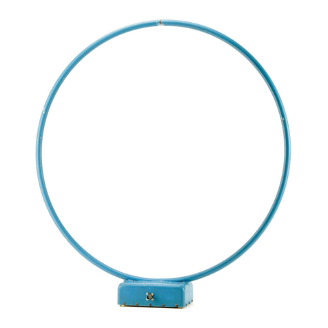
The fixed biconical elements are made from aluminum rod that are welded to the
end pieces. Each element cage has a cross piece connecting the center element to an outer
element to eliminate a common resonance. The elements screw into terminals located at
opposite sides of a circular PVC housing containing the balun network.
A Tripod Mounting Clamp included with the antenna, is used to mount the anten-
na to the EM-6136 Tripod.
Each antenna is calibrated at 1 meter, 3 meters and 10 meters during manufactur-
ing, with the data included in the manual as gain and antenna factors versus frequency.
Refer to Table 1.0 for the maximum power handling capability of the EM-6912A.
The balun, feedline, and element cage design contribute to producing a response
curve that is almost linear. This makes the antenna ideal for vertical and horizontal swept
site attenuation measurements per ANSI and FCC specifications.
To ensure consistency of data collection, the antenna should be orientated in the
same position in each measurement run. In order to maintain the same orientation, the
antenna name label on the antenna housing should:
a) Horizontal orientation: Name label facing downwards to ground.
b) Vertical orientation: Name label on the right side of the antenna
should be on the right side as observed from
the connector end of the antenna.
Note: The data on the calibration chart below 30 MHz
is for informational use only. Calibration toler-
ances are not specified below 30 MHz.
2.0 Specifications
2.1 Electrical
Frequency (calibrated): 30-300 MHz
(Antenna Factor Chart furnished with each antenna.)
