manuals.online logo
Brands
  1. Home
  2. •
  3. Brands
  4. •
  5. Electro-Voice
  6. •
  7. Amplifier
  8. •
  9. Electro-Voice Mixer Amplifier MA-1206 User manual

Electro-Voice Mixer Amplifier MA-1206 User manual

Other manuals for Mixer Amplifier MA-1206

3

This manual suits for next models

1

Other Electro-Voice Amplifier manuals

Electro-Voice 2.0kW User manual

Electro-Voice

Electro-Voice 2.0kW User manual

Electro-Voice PA2450L User manual

Electro-Voice

Electro-Voice PA2450L User manual

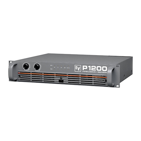
Electro-Voice Precision P1200RL User manual

Electro-Voice

Electro-Voice Precision P1200RL User manual

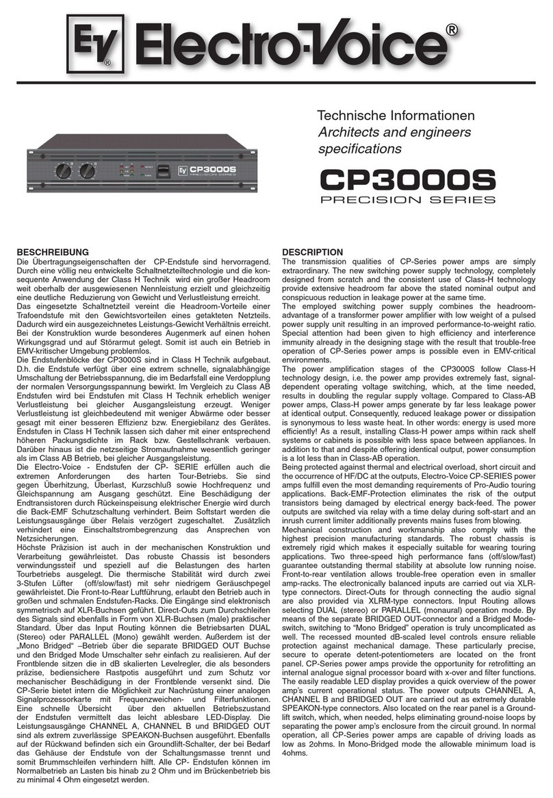
Electro-Voice Compact Precision CP3000S User manual

Electro-Voice

Electro-Voice Compact Precision CP3000S User manual

Electro-Voice Precision P3000 User manual

Electro-Voice

Electro-Voice Precision P3000 User manual

Electro-Voice Compact Precision CP3000S User manual

Electro-Voice

Electro-Voice Compact Precision CP3000S User manual

Electro-Voice CONTRACTOR PRECISION SERIES User manual

Electro-Voice

Electro-Voice CONTRACTOR PRECISION SERIES User manual

Electro-Voice 7300A User manual

Electro-Voice

Electro-Voice 7300A User manual

Electro-Voice Mixer Amplifier MA-1212 Guide

Electro-Voice

Electro-Voice Mixer Amplifier MA-1212 Guide

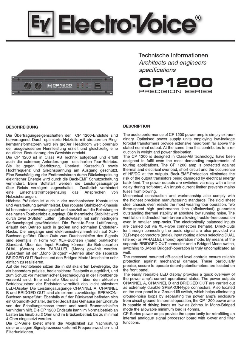
Electro-Voice Precision CP 1200 User manual

Electro-Voice

Electro-Voice Precision CP 1200 User manual

Electro-Voice 7300A Operation manual

Electro-Voice

Electro-Voice 7300A Operation manual

Electro-Voice 7100 Operation manual

Electro-Voice

Electro-Voice 7100 Operation manual

Electro-Voice Mixer Amplifier MA-1212 User manual
Electro-Voice

Electro-Voice Mixer Amplifier MA-1212 User manual

Electro-Voice 7600 User manual

Electro-Voice

Electro-Voice 7600 User manual

Electro-Voice CPS 1 User manual

Electro-Voice

Electro-Voice CPS 1 User manual

Electro-Voice Precision Series P1250 User manual

Electro-Voice

Electro-Voice Precision Series P1250 User manual

Electro-Voice AP2800 Operating instructions

Electro-Voice

Electro-Voice AP2800 Operating instructions

Electro-Voice ELETRO-VOICE CPS2.4 User manual

Electro-Voice

Electro-Voice ELETRO-VOICE CPS2.4 User manual

Electro-Voice PA1250T User manual

Electro-Voice

Electro-Voice PA1250T User manual

Electro-Voice E-V 1144A User manual

Electro-Voice

Electro-Voice E-V 1144A User manual

Electro-Voice Precision P1200 RT User manual

Electro-Voice

Electro-Voice Precision P1200 RT User manual

Electro-Voice Dynacord Linear Precision L 1000 User manual

Electro-Voice

Electro-Voice Dynacord Linear Precision L 1000 User manual

Electro-Voice PA2450L User manual

Electro-Voice

Electro-Voice PA2450L User manual

Electro-Voice Precision P 1200 User manual
Electro-Voice

Electro-Voice Precision P 1200 User manual

Popular Amplifier manuals by other brands

Magnat Audio EDITION FOUR Owner's manual/warranty document

Magnat Audio

Magnat Audio EDITION FOUR Owner's manual/warranty document

Inter-m PA-2000A Operation manual

Inter-m

Inter-m PA-2000A Operation manual

Yamaha TX6n owner's manual

Yamaha

Yamaha TX6n owner's manual

Peavey TNT 150 user guide

Peavey

Peavey TNT 150 user guide

Bosch LBB 1903/10 Installation and user instructions

Bosch

Bosch LBB 1903/10 Installation and user instructions

Avocent Emerge DA1200D Installer/user guide

Avocent

Avocent Emerge DA1200D Installer/user guide

Redgum RGi35 operating instructions

Redgum

Redgum RGi35 operating instructions

Cambridge Audio AXA25 user manual

Cambridge Audio

Cambridge Audio AXA25 user manual

Alpine MRP-M200 owner's manual

Alpine

Alpine MRP-M200 owner's manual

Technical Pro H1502UrBT user manual

Technical Pro

Technical Pro H1502UrBT user manual

FMS EMGZ307 operating manual

FMS

FMS EMGZ307 operating manual

Racal Instruments 5601 user manual

Racal Instruments

Racal Instruments 5601 user manual

Valcom V-1094A Technical specifications

Valcom

Valcom V-1094A Technical specifications

Cambridge Audio 851D user manual

Cambridge Audio

Cambridge Audio 851D user manual

QSC 3800 Specifications

QSC

QSC 3800 Specifications

NAD C300 owner's manual

NAD

NAD C300 owner's manual

Rotel RMB-1077 owner's manual

Rotel

Rotel RMB-1077 owner's manual

Peavey Monitor 300 Series operating guide

Peavey

Peavey Monitor 300 Series operating guide

manuals.online logo
manuals.online logoBrands
  • About & Mission
  • Contact us
  • Privacy Policy
  • Terms and Conditions

Copyright 2025 Manuals.Online. All Rights Reserved.

Electro-Voice®®
®®
®
MA-1206 and MA-1212 User Manual
User Manual
MA-1206/MA-1212
Professional Mixer/Amplifiers
Electro-Voice®®
®®
®
MA-1206 and MA-1212 User Manual
Table of Contents
Typical Connections ............................................................................... 3
Features ................................................................................................. 2
Description ............................................................................................. 2
Installation .............................................................................................. 3
Grounding .................................................................................. 3
Ventilation .................................................................................. 3
Key Input Connections ............................................................... 3
Typical Connectons ................................................................... 4
Output Connections ................................................................... 6
Hig Impedance/Constant-Voltage Systems .............................. 7
Operation ................................................................................................ 8
Front Panel Controls .................................................................. 8
Rear Panel Controls and Connections ....................................... 9
Appendix A: Limited Warranty .............................................................. 13
Exclusions and Limitations....................................................... 13
Obtaining Warranty Service ..................................................... 13
Ot er Rig ts ............................................................................ 13
Appendix B: Safety Guidelines ............................................................. 14
AC Power Supply..................................................................... 14
DC Power Supply .................................................................... 14
Safety Precautions................................................................... 14
Tec nical Specifications ....................................................................... 16
Electro-Voice®®
®®
®
MA-1206 and MA-1212 User Manual
Page 2
Features
•Level controls for each input and a master volume control.
•Individual bass and treble tone controls.
•Automatic muting circuit with threshold adjustment.
•600 ohm transformer-isolated line input for paging, with
automatic muting of all other inputs.
•Low distortion.
•Output protection circuit.
•Au iliary line level inputs with internal mi ing for stereo source.
•Balanced line level output.
•Insertion point between preamp and amplifier.
•Phantom power on all microphone inputs enables microphones
to be used without separate power supplies.
Description
The Electro-Voice MA series of mi er-amplifiers are available with output
power ratings of 60 (MA-1206) or 120 (MA-1212) watts. The MA series
products provide background music and allow paging in environments
such as churches, small businesses, and professional offices.
The MA inputs include 10 combination balanced or unbalanced
Microphone/AUX level connections, 2 stereo AUX summing inputs,
telephone paging and Power Amp In connections. Inputs to Mic 1 can
be set to automatically mute the other Mic and AUX level input channels.
Input sources to Au 1 and 2 may include: tape players, compact-disc
players, AM/FM tuners, mi er-preamplifiers or wireless microphones.
The telephone paging input accepts the signal from a standard 600 ohm
paging line.
The Power Amp In jack, along with the Preamp Out jack, is provided to
insert an equalizer or other signal processing device before the power
amplifier.
The amplifier includes protection circuitry to prevent damage from either
open or shorted speaker lines.
An adjustable automatic muting circuit mutes all other inputs when the
paging input is activated.
Electro-Voice®®
®®
®
MA-1206 and MA-1212 User Manual
Page 3
Installation
To avoid hum in the output, be certain that all input cables are physically
separated from power wiring and transformers. Speaker cables should
also be kept away from input cables and power cables.
An e ample of what sources and output devices would be connected to
this unit is shown in Figure 1.
Grounding
Ground the chassis of the unit by using the ground terminal located on
the back panel. For the best grounding, connect the amplifier to an earth
ground such as a cold water pipe or ground rod. If additional equipment
is installed along with the amplifier, make sure their chassis are
connected together to reduce noise and hum.
Ventilation
To remove the heat generated by the power amplifier, provide ample
ventilation around the unit. Avoid blocking or impeding the vent slots in
the cabinet.
Locate the unit where it is free from direct sunlight, humidity, dust and
vibration.
Key Input Connections
Microphones. The Mic inputs are for use with balanced Low Impedance
(appro imately 200 ohms) or unbalanced high impedance
(appro imately 20k ohms) microphones. For high impedance
microphones, cables should be as short as possible in order to avoid
loss of High Frequency response. The results will vary with the
microphone and cable capacitance. However, a limit of 30 feet is
recommended.
The Mic inputs may be accessed by either XLR connectors or ¼ phone
plugs.
Figure 2 shows the wiring configurations of both unbalanced and
balanced microphones using either ¼ or XLR type connectors.
Electro-Voice®®
®®
®
MA-1206 and MA-1212 User Manual
Page 4
Typical Connections
Figure 1:
Typical Connections
Electro-Voice®®
®®
®
MA-1206 and MA-1212 User Manual
Figure 2:
XLR and Jack Inputs
Figure 2 shows the wiring configurations of both unbalanced and
balanced microphones using either ¼ or XLR type connectors.
Phantom Power: Phantom power allows the use of microphones without
separate power supplies on the Mic inputs. When phantom power is on,
24 V dc is produced at pins 2 and 3 on the Mic inputs. To enable
phantom power simply move the selector switch to the 24v position
above the desired input connector.
Microphone auto muting input: When a microphone or other source is
connected to input 1 and the front panel mute switch in the on position,
advance the threshold control to the point where the typical voice, and
not noise in the room, will operate the mute circuit. The microphones on/
off switch may be on, with the actual voice announcement triggering the
mute. If you want to defeat the muting function, place the mute switch in
the off (defeat) position.
Au iliary 1 and 2: High-level unbalanced sources may be connected to
the Au 1 and 2 jacks on the back panel.
Appropriate sources include a tape player, compact-disc player, AM/FM
tuner, mi er-preamplifier, wireless microphone or turntable equipped with
a ceramic or crystal cartridge. Use a single-conductor shielded cable.
Turntables usually have a separate ground wire. Connect this wire to the
ground terminal on the back panel to minimize hum.
Page 5
Electro-Voice®®
®®
®
MA-1206 and MA-1212 User Manual
Page 6
The set of RCA jacks (R and L) provided on the AUX 1 and 2 inputs are
designed to match to the two outputs of the typical stereo source. The
jacks are in parallel through internal series resistors and mi both
channels. The series resistors are chosen to avoid undesirable loading
effects on the output stage of typical stereo sources.
Plug monaural high-level unbalanced sources into either the R or L
jacks.
Paging: The voice paging signal from a 600 ohm balanced audio paging
line (such as a PBX system) may be connected to the au paging input
on the back panel.
Power Amp In: The Power Amp In jack provides direct access to the
power amplifier. It requires a line- level signal fed through a RCA type
phono plug wired with a single-conductor shielded cable.
Output Connections
The amplifier-can accommodate both Low Impedance and high
impedance constant-voltage speaker loads (25, 70.7, and 100 volt lines).
There are several considerations in the connection of a speaker or
multiple speakers to an amplifier:
1. Matching speaker impedance to the amplifiers rated Impedance: In
general, power amplifiers deliver rated power into a rated load
impedance. Lower impedances reduce the ma imum available power
available at rated distortion. Significantly lower impedances may cause
the amplifiers protection fuses to open, especially at high volume levels.
These low impedances should be avoided.
2. Power loss in speaker wire: The impedance of the speaker connecting
wire would ideally be zero, so all of the amplifier output power can be
delivered to the speaker load. However, the impedance of a longer
speaker wire installation can become a significant proportion of the total
impedance. Thus, part of the amplifier power is lost in the wire and the
power to the load is reduced. Wire impedance is highest for the longest
wire runs and smallest wire sizes.
Table 1 shows the two wire cable (copper) lengths permissible for a
number of wire sizes and speaker impedances to avoid a loss of more
than 0.5 dB. For a 1 dB loss (basically imperceptible), double the wire
lengths. For a 2 dB loss, multiply the lengths by 4.4.
In general, note that high load impedances allow the use of longer,
smaller gauge wiring.
Electro-Voice®®
®®
®
MA-1206 and MA-1212 User Manual
3. Balancing relative speaker levels: There is no easy, electrically
efficient way to balance and adjust the sound levels among multiple
speakers in a low impedance installation. Constant-voltage high
impedance systems ease this process because they typically employ
speakers equipped with transformers with multiple input taps marked in
watts.
Low Impedance Speakers. The low impedance ohm output terminal is
provided for direct connection of one or more standard low impedance
speaker systems. For e ample, connect a single speaker system to the
common and 4 ohm terminals. Correct connection of several low
impedance speakers must follow the rules of proper series and parallel
impedance summation.
High Impedance/Constant-Voltage Systems
Installations that require high impedance speaker loads permit smaller
diameter wire for a given power loss in the speaker lines. Usually, low
impedance speakers are still used in such systems, but transformers are
used at the speaker locations to increase the impedance to the desired
value. Multiple transformer taps, labeled in watts, permit easy adjustment
of the individual speaker levels. Use simple parallel connection of the
transformer primaries (inputs). This eliminates the determination of load
impedance and series-parallel speaker connections.
For proper operation, all speakers should have transformers with the
same voltage rating, i.e. 25, 70.7, or 100 volts. The total of all the power
taps should be equal to or less than the amplifiers rated output power.
When the total equals the rated power, the amplifier may deliver rated
power to the load, depending on the input signal levels. Totals less than
the rated amplifier output will not damage the amplifier since the
resultant load impedance is higher than the amplifiers rated impedance
and thus only reduces the power delivered at ma imum amplifier level.
How ever, avoid power totals greater than rated amplifier power, since
the total load impedance drops below the amplifiers rated load.
Preamp Out: The Preamp Out jack provides a line-level mi of the input
signals, fed through a 1/4 inch phone plug wired with a single-conductor
shielded cable.
Use the signal at the Preamp Out jack to feed an e ternal equalizer or
signal processor whose output would connect to the Power Amp In jack.
Page 7
Electro-Voice®®
®®
®
MA-1206 and MA-1212 User Manual
Page 8
The preamplifier output may also be used alone to drive an additional
e ternal power amplifier with its own set of speakers. When the Preamp
Out jack is used, the mi ed signal to the internal power amplifier is
interrupted.
The balanced line level XLR output connector is ideal for feeding an
e ternal recording device or assistive listening system. When the rear
panel switch is in the fi ed position, the master volume control does not
affect the level at this line out jack, which permits setting the tape
recorders input level independent of system volume. The tape output is
buffered, so that an improper load will not affect system performance.
Operation
Figure 3:
Front Panel Layout
Front Panel Controls
(Refer to Figure 3)
1. Mute function switch: This switch lets you turn the Voice
Priority or page ducking function on or off of input 1 (1).
2. Au iliary 1&2 : These controls adjust the level of the two stereo
summing au iliary inputs. Input 1-10: These controls adjust the
levels of the 10 multi-use inputs.
3. Music signal monitor output level control: This control is a
screwdriver adjustment and lets you individually set the volume
of a headphone that is connected to the MONITOR OUTPUT
(4) or a small speaker connected to the 1w 8 ohm terminals on
the rear panel (25). Turning the control clockwise increases the
volume of the corresponding source.
Electro-Voice®®
®®
®
MA-1206 and MA-1212 User Manual
Page 9
Front Panel Controls (cont )
5. Overload indicator light: When the amplifiers output overloads
the OVER LOAD indicator illuminates and interrupts the output
signal. The output will resume when the volume is lowered or
the offending load is remove from the output line.
6. Power Switch and Power Indicator: This switch supplies power
to the unit. The power indicator lights when power is applied to
the unit.
7. Master: This control adjusts the level of the combined input
signals to the power amplifier.
8. Treble: This control adjusts the high frequency response by
providing up to 7 dB of boost or 12 dB of cut at 10 kHz.
9. Bass: This control adjusts the low frequency response by
providing up to 7 dB of boost or 12 dB of cut at 100 Hz.
Rear Panel Controls and Connections
(Refer to Figure 4)
10. Main cord connector: This connector is for the connection of the
supplied AC line cord.
11. AC fuse: The fuse can only be changed, in the event of a fault or
changing the supply voltage. This service should only be done by
an EV service center.
12. GND screw: In case the main outlet does not provide a ground
conductor, this screw offers the possibility to ground the amplifi-
ers metal parts.
Figure 4:
Rear Panel Layout