Electrolux Professional XBM10 User manual

Refer to the numbered drawings that go with the numbered paragraphs in the
instructions.
GB
1XBM10 GB 06 2015
1.1a 1.1b
09/2021
Contents
Introduction 1
Introduction 1
Installation. 1
Use, safety 3
Cleaning and hygiene 5
Fault finding 5
Maintenance 6
Compliance with legislation 8
Parts list - exploded view A
Electrical diagrams
Introduction
The User Manual contains useful information for the user on how to
work correctly and in complete safety, and is designed to make it
easier to use the machine (called «machine» or «appliance» below).
What follows is in no case intended to be a long list of warnings and
constraints, but rather a series of instructions meant to improve the
service provided by the machine in every respect, and particularly
to avoid a series of injuries or damage to equipment that might
result from inappropriate procedures for use and management.
It is essential that all the people responsible for transporting, ins-
talling, commissioning, using, maintaining, repairing or dismantling
the machine should consult this manual and read it carefully before
proceeding with the various operations, in order to avoid any in-
correct or inappropriate handling that might be result in damage
to the machine or put people’s safety at risk.
It is just as important that the Manual should always be available
to the operator and it should be kept carefully where the machine
is used ready for easy and immediate consultation in case of any
doubt, or in any case, whenever the need arises.
If after reading the Manual, there are still any doubts concerning
how to use the machine, please do not hesitate to contact the
Manufacturer or approved After Sales Service provider, who
is constantly available to ensure quick and careful service for
improved machine operation and optimum efficiency.
Note that the safety, hygiene and environmental protection stan-
dards currently applicable in the country where the machine is
installed must always be applied during all phases of machine
operation. Consequently it is the user’s responsibility to ensure
that the machine is operated and used solely under the optimum
safety conditions laid down for people, animals and property.
Introduction
1.1 DESCRIPTION
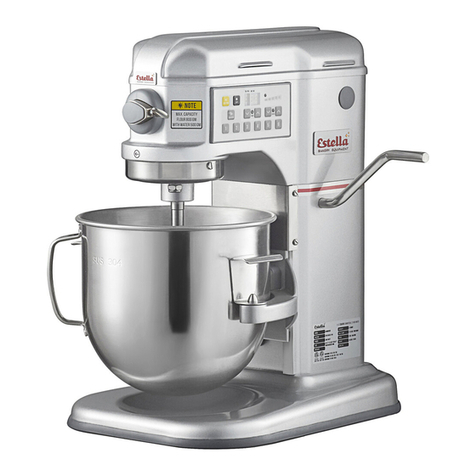
•This mechanical beater-mixer is an appliance for professional
use in bakery-patisserie and in the kitchen designed for kneading,
mixing and whipping all kinds of food products. The version A
(with accessories socket), adapted in the kitchen, allows driving
machine accessories.
A Stainless steel bowl, 9.9 litre capacity
BRemovable safety guard
CPlanetary gear system
DH12 type accessory socket
EHead
FTop cover
GControl panel
HFrame
IBowl cradle
JPads
KSpeed control lever
• 3 tools are available as standard supply:
AA spiral hook for kneading dough
BPaddle for mixing.
CWhisk for emulsions
• Optional equipment:
- Accessory machines: vegetable slicer, mincer, etc.
(see §3.6).
Installation
ATTENTION!!
Machine storage: -25°C to +50°C
Ambient temperature for operation: +4°C to +40°C
This machine is for professional use and must be used by staff trained to use, clean and maintain it, in terms or reliability and safety.
Use the machine in adequately lit premises (See applicable technical standard for the country of use. In Europe, refer to standard
EN 12464-1)
When handling the machine, always check that the parts taken hold of are not mobile elements: risk of dropping and injury to the
lower limbs.
The machine is not designed for use in explosive atmospheres.
The reference language for these instructions is French.

XBM10 GB 09 2021 2
2.2 LOCATION
• The beater mixer must be fitted on a support that is perfectly
stable and horizontal, between 400 and 700 mm high and not
resonant (e.g. a unit, table, etc.).
2.3 ELECTRICAL CONNECTION
ATTENTION!!
Connection to the electrical power supply must be done according to proper professional practice by a qualified and authorised
person (see current standards and legislation in the country of installation).
If an adapter is used on the socket, a check must be made that the electrical characteristics of this adapter are not lower than
those of the machine.
Do not use multiple plugs
The AC power supply to the machine must comply with the following conditions;
- Maximum voltage variation: ±5%
- Maximum frequency variation: ±1% on a continuous basis, ± 2% over short periods
ATTENTION: the electrical installation must comply (for design, creation and maintenance) with the legal and standard
requirements in the country where used.
- Check that the electric mains voltage and the value shown on the specification plate.
- The machine’s electrical power supply must be protected against voltage surges (short-circuits and excess voltages) by using
fuses or thermal relays of the appropriate gauge relative to the place of installation and machine specifications.
ATTENTION: Concerning protection against indirect contact (depending on the type of power supply provided and
connection of the exposed conductive parts to the equipotential protection circuit), refer to point 6.3.3 of EN 60204-1 (IEC
60204-1) with the use of protection devices for automatic shut-off of power in the event of an insulation fault with a TN or
TT, system, or for the IT system, with the use of a permanent insulation or differentials controller for automatic shut-off.
The requirements of IEC 60364-4-41, 413.1 must apply for this protection.
For example: in a TT system, a differential circuit breaker must be installed upline of the power supply, with a suitable power
cut-off (e.g.: 30 mA) on the earthing installation for the place where it is planned to install the machine.
ATTENTION: Failure to comply with these instructions means the customer runs the risk of machine failure and/or acci-
dents due to direct or indirect contacts.
• This mixer-whisk is to be supplied with three-phase current.
Earthing is mandatory, using a green/yellow
conductor.
NO EARTH PLUG = NO PROTECTION = RISK OF
ELECTROCUTION =
Note: The earth values are defined according to the
residual differential current. Non-compliance with these
instructions may result in invalidation of the warranty.
No damage caused by an earth connection fault will be co-
vered by the warranty.
1) Three-phase motor
• A standard wall socket with 3 poles + Earth, rated at 20A will
be required and a matching watertight plug fitted to the power
supply cable.
• Check the direction of rotation:
- of the planet gear, anti-clockwise direction (see arrow on
head)
- of the tool, clockwise direction.
• If the direction of rotation is reversed, change over the two
phase wires on the plug.
• Connection is made at higher voltage for 400V). For
connections to lower voltage supplies 230V proceed as
follows:
- Unplug the machine.
- Remove the rear plate.
This appliance must be earthed with a green/yellow wire.
2.3b
- Refer to the wiring diagram in § 6.6.
- Change over the integral plate wire by moving the cable lug
from the terminal marked for the higher voltage (400V) onto
that for the lower voltage (230V).
- Change over the plate straps on the terminal plate.
- Check the direction of rotation and refit the plate.
2.3c
2.1
2.1 DIMENSIONS - WEIGHT (for information only)
- Gross weight when packaged: 58 Kg
- Net weight when equipped: 37 Kg
- Packaging dimensions: 700 x 540 x 920 mm
- Overall dimensions 601 x 454 x 740 mm

3.1 a
3.2d
3.2a
3.2a
3.3b
3.3a
3.3c
3.3d
3.2a
3.2a
3.3a
3XBM10 GB 11 2018
Use, safety
ATTENTION!!
Clean the machine properly prior to its first use
Never introduce the hand into the work zone when the machine is operating: risk of injury. Neutralising or modifying the safety
systems is formally prohibited: Risk of permanent injury!!!!
Check that the safety devices operate correctly each time before using (see paragraph on «safety system adjustments»).
Never put a hand, a hard or frozen object in the appliance
For health and safety reasons, always use a washable or disposable strong head covering that covers the hair completely.
3.1 OPERATION - SAFETY
• The safety of the user is guaranteed by:
- The safety guard which allows the tool to be maintained at a
standardised distance and which stops the motor when it is
raised.
- The machine only starting when the support is in the work
position and the safety guard lowered.
- A time of less than three seconds for the machine to stop
regardless of the speed.
- A no volt release system which means that the B, F or G button
need to be pressed to restart the machine.
- Protection against the motor over-heating, temperature probe.
- Compliance with the instructions given in this manual for using,
cleaning and maintaining the machine.
Control panel:
ASTOP button
BLow speed
CDecrease timer time
DDisplay timer
EIncrease timer time
FHigh speed
GPulse ON button
• The mixer can only be started normally if the safety guard bowl
cradle assembly is in the work position the bowl is in position
on the cradle.
Always move the safety guard by its handle.
a) Operation:
- Press button Bor Fto start at low speed or high speed.
c) Timed operation:
- Use buttons Cor E, Dshowing the time selected and then
press Bor F.
Note:
- To change the time remaining, press key Aand then
alter it with keys Cor E; restart the cycle by pressing
key Bor F.
- The time selected at the start of the cycle is held in memory.
- To stop permanently a cycle in progress, press key A twice.
d) Continuous operation:
1- Selection of «-----» on Eby pressing and holding down key C.
2- Start by pressing key Bor F.
3- Stop by pressing key A.
3.2 FITTING THE BOWL AND TOOLS
• Raise the safety guard using the handle, and the cradle will
be lowered automatically.
- Place a tool inside the bowl.
- Push the tool onto the tool holder spindle, then turn it anticlo-
ckwise ( ) to lock it in position.
- Push the safety guard back by means of the handle, and the
bowl will be automatically locked into position.
Note: If the bowl is not fitted correctly, it will not be
possible to close the safety guard completely. Do not
force it: refit the bowl correctly on the 2 pins.
3.3 FITTING - REMOVING THE SAFETY GUARD
• To remove the safety guard, proceed as follows:
1) Raise the safety guard to its upper stop using the handle.
2) Turn the two lateral handles towards the rear so that the two
safety guard rods are aligned with the two holes in the handles.
3) Pull the guard horizontally to remove it.
• To fit the guard:
1) Make sure that the holes in the handles are lined up with the
rod holes.
2) Insert the two guard rods into the handles at the same time.
3) Turn the two handles towards the front to lock the guard into
position.
4) Lower the guard using the handle.
§5.3
Any other use than that described in this manual will not be consi-
dered normal by the manufacturer.
Do not use the machine without
the bowl.

Flour/water paste Kg flour 3,5
(Moisture content 50%)
Pizza Kg dough 3
(
Moisture content 40%)
Shortcrust pastry: 3
Sweet pastry
Croissant dough Kg flour 3
Brioche dough 3
Choux pastry Litres of water 3
Meat Kg 5
Mashed potato Kg potatoes 5
Fondant Kg of sugar 3
Egg whites 16
Genoese sponge 15
Sponges
Number of eggs
15
Meringues Kg of sugar 0,75
3.43.4
}
}
3.6 b
3.6 a
3.6 a
3.6 a
XBM10 GB 11 2018 4
3.4 CHANGING SPEEDS AND SPEED SELECTION
• The variable-speed belt drive provides the user with a conti-
nuous range of speed to carry out all sorts of work under optimal
conditions for output and quality.
• To change speed, proceed as follows:
- Press the speed 1 or speed 2 button.
- Pull the lever towards you to decrease the speed and push it
away to increase it.
Never operate the speed lever when stopped.
- Always start in slow speed to prevent splashes or flour dust
being given off, then gradually increase the speed, bearing in
mind that the drive force (the torque) increases as the speed
is decreased.
Note:
The lever remains at the chosen speed through its
self-maintaining system in any position.
- If the belt slips, decrease the speed.
- After finishing the work, put the lever back to slow speed, press
the stop button and then lower the bowl.
• Speeds to be used for the tools.
VSpeed of planetary gears (rpm)
PLow speed
GHigh speed
Normal work recommended
3.5 MAXIMUM CAPACITIES
• The beater’s working capacity depends upon:
- The tool used.
- The nature, quantity and density of the mass to be worked.
- The optimum speed for quality results.
• Too large a quantity is always detrimental to the quality of
the work and the life of the mechanical parts of the machine
and may lead to overheating of the motor and abrupt stop-
page (See § 5.1).
• Maximum recommended quantities.
Products Reference Max. quant Tools
3.6 ACCESSORY SOCKET
• This mixer is equipped with a H12 type variable speed drive
hub to drive the following accessories:
- H 70 H: dia. 70 mm mincers, ENTERPRISE or UNGER systems.
Delivered with hopper, pusher, knives and plates.
- CX 21D: Safety vegetable preparation machine that can be
disengaged, equipped with plates for slicing, shredding,
grating, etc.
- P 200 H: Sieve for mashed potato, purees, soups, fruit com-
potes, fish soups, etc Delivered with 3 different screens.
Consult the separate instruction sheet for each accessory
appliance.
• To fit one of the accessories, proceed as follows:
- Fit the accessory which corresponds to the work to be carried
out.
The machine must be stopped before fitting or removing
accessories.
- Lift up the cover plate H.
- Present the accessory Band introduce cone Cin the beater
socket A.
- Introduce the square male shaft Dinto the drive shaft of the
socket A, turning B.
- Place the pin Ein line with the hole I and insert the accessory
as far as possible in the socket A.
- Tighten the lock screw G(clockwise direction ( ) in cavity
F.
- Select a suitable speed for the accessory.
Note: To remove the accessory, unscrew G by at least
4 turns to release it from cavity F.
• Speeds for the accessories:
VP - Accessory socket speed (rpm)
Work recommended

5XBM10 GB 06 2015
Cleaning and hygiene
ATTENTION!!
Before dismantling any part, disconnect the appliance from the power supply.
Before using any cleaning product, be sure to read the instruction and safety instructions accompanying the product and use
appropriate protective equipment.
Do not clean the machine with a pressure cleaner
4.1 BETWEEN TWO SESSIONS
• Remove the bowl and tool.
• Using hot water and detergent / disinfectant or degreaser (if
working with greasy products), immerse and wash the inside of
the bowl and the tool in the sink, then rinse in clean water and dry.
• Clean the planetary gear housing, the tool holder spindle and the
safety guard with a damp sponge and a detergent - disinfectant
product, then rinse in clean water.
• Do not put the tools in a dishwasher as this causes the alumi-
nium parts to blacken.
Note: Use cleaning products that are compatible with
the aluminium and plastic (polycarbonate) parts.
• Do not clean the machine under a water spray.
4.2 AFTER USE
• Disconnect the machine.
• Remove the safety guard (see §3.3).
• Clean the bowl, tools and guard by immersing them in hot
water and detergent / degreaser or disinfectant in a sink, then
rinse in clean water and dry. Only the bowl may be cleaned in
a dishwasher.
• Do not put the tools in a dishwasher as this causes the alumi-
nium parts to blacken.
• Clean the planetary gear housing, the tool holder shaft and the
support, paying particular attention to the bowl handles and the
outside of the whisk where appropriate using a damp sponge
and a disinfectant / detergent product, then rinse.
• Check that the various parts have been cleaned correctly.
Note: Check that the products used for cleaning are
compatible with the machine part materials.
• Do not use abrasive detergents or sponges as these may
scratch the surfaces, in particular the plastic guard.
• Read the manual of each accessory for the cleaning instructions.
• Do not clean the machine under a water spray.
Occasionally: (at least once a month)
• Wipe and lightly lubricate the raising and lowering pins and
the safety guard pivots with Vaseline.
4.3 STRAY FLOUR PARTICLES:
In order to reduce the emission of stray flour particles while
loading the bowl, it is recommended as follows:
- Empty the flour bag or the container containing the flour without
shaking it.
- Pour in the water before putting the flour in if that is possible
- Always start at slow speed during the water/flour mixing
- Do not shake the empty flour bag. Roll it up carefully.
Keeping to these simple rules will contribute to reducing the
emission of flour dust and consequently reducing the risk of
allergy linked to that dust.
Fault finding
5.1 THE BEATER WILL NOT START
• Check that :
- The machine is plugged in.
- The electrical power supply to the socket is correct.
- The safety guard is lowered correctly and the cradle is in the
work position.
- The bowl is in position on the cradle.
• If the beater stops during operation:
- The motor heat sensor has been triggered. Wait a few minutes
before starting again.
- Reduce the speed or the load (see § 3.4 and 3.5).
5.2 ABNORMAL NOISE OR OPERATION
• Metal noise
- Distorted tool that is rubbing or rotating in the wrong direction
(See § 2.3).
- Bowl damaged, not in place (See § 3.2).
- Lack of grease on the planetary gears (See § 6.1 for
dismantling instructions).
• Piercing noise
- The belt is slipping, causing it to wear quickly.
- Defective belt (See § 6.2 for replacement and tensioning
instructions).
• Noisy motor
- Motor running on 2 phases. Check the connection and the
electrical circuit.
• Lacks power:
- Check the pulley flanges slide properly and the condition of
the belt (see § 6-2).
- Motor running on 2 phases (see § 6-6).
- Power supply voltage not correct, with abnormal heating of
motor
- Working speed too high: reduce the speed.
- Load too great: reduce the quantity.
If the problem persists contact your supplier’s service
department.

6.1
XBM10 GB 02 07 6
5.3 BLOCKAGE OF A TOOL ON THE TOOL HOLDER SPINDLE
- By tapping The tool with A mallet after clearing The pin from
The bayonet.
- Rub down the distorted part where necessary.
If the problem persists contact your supplier’s service
department.
• Generally due to poor cleaning or a distorted tool bore caused
by a blow.
• If the tool is starting to seize, do not force it. Apply oil or pe-
netrating fluid and wait a few minutes for the product to work.
• Work it gradually, applying measured force:
- Turning it, using a to-and-fro movement.
5.4 RAISING AND LOWERING SYSTEM
• If the lever for raising and lowering becomes difficult to operate :
- Check if the 2 rods supporting the cradle have not suffered
any impacts. Smooth with abrasive cloth if necessary.
- Lightly oil the two posts with Vaseline.
- If necessary, remove the top cover and lightly oil the upper
parts of the two rods and the hinge pins.
5.5 SPEED CONTROL LEVER
• If the speed control lever becomes hard:
- lightly oil the variable pulleys and grease the sliding gear
drive pin.
• If the lever self-maintenance system is no longer working, refer
to § 6-3 speed adjustment.
If the problem persists contact your supplier’s service
department.
Maintenance
ATTENTION!!
Maintenance may only be carried out by a qualified, trained and authorised person
6.1 MECHANICAL PARTS
• At least once a year it is recommended to:
- If necessary, grease the planetary gears with a high adhesive
grease (ask us, see § 6-4).
- Clean out the belt dust and flour from inside the machine using
a vacuum cleaner.
• Access to electrical components:
- disconnect the machine.
Residual voltage at the capacitor terminals
• The capacitors may still have an electric charge. In order to avoid
any risk when carrying out an intervention, it is recommended to
discharge them by connecting their terminals using an insulated
conductor (e.g. screwdriver).
6.2 CHANGING THE BELT
- Stop the beater in high speed (position 8) and unplug it.
- Remove the screws from the upper cove and disconnect it to
separate it from the head.
- Put the lever to the min. speed position (No. 1).
- Then put the lever to the max. speed position (No. 8).
- Disengage the belt from the driven pulley.
- Hold the belt on the side and pull towards you until it releases
from the variable drive pulley.
To fit the new belt:
- Present the belt onto the drive pulley.
- Pull firmly to engage it as far as possible.
- Engage the belt on the driven pulley.
- Turn the driven pulley by hand to even out the position of the
belt.

6.4
6.3
7XBM10 GB 06 2015
6.3 DISMANTLING THE PLANETARY ASSEMBLY
• Proceed as follows:
- Remove the cover with the rear screw, raising it slightly and
pushing it forwards so as to gain access to the transmission
and disconnect the electrical harness.
- Put the lever to the min. speed position (No. 1).
- Then put the lever to the max. speed position (No. 8).
- Disengage the belt from the driven pulley.
- Hold the belt on the side and pull towards you until it releases
from the variable drive pulley.
- Unscrew the driven pulley nut. (19 mm Hex spanner).
- Remove the driven pulley.
- Tap the end of the shaft with a mallet to lower the planetary
gear output shaft assembly.
Support the planetary gear assembly to avoid it falling.
• Clean the mixer and grease the gears and crownwheel with
special food compatible grease (ask us).
• Fit the planetary gear, tighten the screw of the driven pulley
and tension the belt (see § 6.2).
• Run the mixer at low speed for a short while to distribute the
grease evenly then increase the speed.
6.4 SPEED SELECTION
In normal operation, on changing from high speed to low speed,
the lever moves back slightly before holding in position.
• If it does not stabilise, make the following adjustment:
- Run the beater at low speed (1) and then stop it.
- Unscrew the speed change lever.
- Remove the cover to gain access to the mechanism and
retighten the lever.
- Release the lock-nut on the backstop screw A.
- Start the beater up again and loosen the backstop screw until
the lever is held at all speeds.
- Tighten the lock-nut.
- he beaters are factory-set to run at approximately 38 to 180
rpm (planetary gear speed).
6.5 CHECKING THE SAFETY DEVICE
• The proper operation of the safety device must be checked
before each time the machine is used. The motor must stop
in less than 4 seconds on opening the safety guard 30 mm
at the front between the bowl and the guard and on lowering
the bowl.
• If this does not happen:
- Do not use the machine.
- Have it adjusted by the service department of your local
dealer.
6.6 ELECTRICAL COMPONENTS
See electrical diagrams.
• Check the condition of the power cable and the electrical
components regularly.
• Access to electrical components:
- Unplug and put the machine on its back.
- Remove the base plate (4 screws – 8 mm spanner).
• Identification of the motor wires:
- Power circuit: black
- Motor: A: red - B: green - C: yellow - D: white - E: blue - F:
black – G: orange – H: violet – I: grey – J: brown – K: pink.
- Phases: LSingle phase; - Neutral: N
- Earth: Green/Yellow B/C
• Component identification:
S1 : Guard safety device
S2 : Motor sensor
S3 : Bowl presence safety device
M : Motor
CC : Control board
CPU : Electrical power board
6.7 ADDRES SFOR MAINTENANCE
We recommend that you contact first the seller of the machine
first of all.
For all requests for information or orders for spare parts,
quote the type of machine, the serial number and the
electrical specifications.
The manufacturer reserves the right to modify and make impro-
vements to the products without giving prior warning.
Supplier’s stamp
Date of purchase: ...............................................
The machine must not operate if the bowl is not
in position on the cradle.

The machine is designed and made in compliance with:
- Machine directive 2006/42 EEC,
- The EMC directive 2014 / 30 EU,
- 2011/65/EU Directive on the restriction of the use of certain
hazardous substances
- «WEEE» Directive 2002/96/CEE
The symbol “ ” on the product indicates that this product must
not be treated as household waste. On the contrary, it must be taken
to an electric and electronic equipment recycling point. By ensuring
that the product is properly disposed of in this way, you are helping
to prevent damage to the environment and human health that could
otherwise occur if the product is not disposed of in a controlled manner.
For more information about the recycling of this product, please contact
the sales department or supplier of the product, the after sales service
or the appropriate waste treatment services.
- «Waste» Directive 2006/12/CEE
The machine is designed in order to contribute as little as possible, if
at all, to the quantity and noxious nature of waste and risks of pollution.
Please comply with the recycling conditions.
- «Packaging and packaging waste Directive 94/62/CEE
The machine packaging is designed in order to contribute as little as
possible, if at all, to the quantity and noxious nature of waste and risks
of pollution.
Please make sure the various packaging materials are disposed of in
the appropriate recycling points.
- European standards:
EN 454- - Beaters-Mixers. Safety and hygiene regulations.
EN 60204-1-2006 machine electrical equipment
This compliance is certified by:
- The CE compliance mark attached to the machine.
XBM10 GB 05 2016 8
Compliance with legislation
- The corresponding CE declaration of conformity, associated
with the warranty,
- This instruction manual, which must be given to the operator.
Acoustic specifications:
- The acoustic pressure level measured in accordance with the
test code EN ISO 3743.1-EN ISO 3744 <70 dBA.
Protection indexes according to standard EN 60529-2000:
- Electrical controls IP55
- Machine as a whole IP23
Electromagnetic compatibility complies with standards:
- EN 55014-1: Emission -
- EN 55014-2: Immunity -
Built-in safety:
- The machine has been designed and manufactured in com-
pliance with the relevant regulations and standards referred
to above.
- Before using the attachment, the operator must be trained
to use the attachment and informed of any possible residual
risks.
Food hygiene:
The machine is made of materials that comply with the following
legislation and standards:
- Directive 1935/2004/CEE: Materials and objects in contact
with foodstuffs.
- Standards EN 601- : Cast aluminium alloys in contact with
foodstuffs.
- Standards EN 1672-2- : Instructions relating to hygiene
The surfaces of the food area are smooth and easy to clean. Use
detergents that are approved for food hygiene and respect the
instructions for their use.
This manual suits for next models
1
Table of contents
