Electron Machinedrum SPS-1 User manual


Limited warranty
Elektron synthesizers are sold with one year full warranty.This warranty covers all malfunctions that may occur from
normal use. Damage caused by careless handling (improper voltage connected, exposure to damp, abuse etc. is not
covered. The unit can only be returned for repair after agreement from Elektron. Customer covers cost of shipping of
malfunctioning unit from customer to Elektron. Elektron covers shipping from Elektron back to customer. Elektron
agrees to offer spare parts and service for all synthesizer produced by Elektron also after the warranty expires as long
as is possible. The warranty applies to the physical unit and applies also for customers buying units second hand
where the warranty still is valid. The warranty is void without a readable serial number label.
Elektron offers ten days money back guarantee for all synthesizers sold directly by Elektron. A returned unit has to be
in condition "as new". The ten days are counted from arrival of the unit. The refund is transferred as we receive the
returned unit. The customer covers the cost of the return shipping.
FCC compliance statement
This device complies with part 15 of the FCC rules. Operation is subject to the following two conditions: (1 This device
may not cause harmful interference, and (2 this device must accept any interference received, including interference
that may cause undesired operation.
NOTE: This equipment has been tested and found to comply with the limits for a Class B digital device, pursuant to
Part 15 of the FCC Rules. These limits are designed to provide reasonable protection against harmful interference in
a residentpial installation. This equipment generates, uses and can radiate radio frequency energy and, if not installed
and used in accordance with the instructions, may cause harmful interference to radio communications. However,
there is no guarantee that interference will not occur in a particular installation. If this equipment does cause harmful
interference to radio or television reception, which can be determined by turning the equipment off and on, the user
is encouraged to try to correct the interference by one or more of the following measures:
• Reorient or relocate the receiving antenna.
• Increase the separation between the equipment and receiver.
• Connect the equipment into an outlet on a circuit different from that to which the receiver is connected.
• Consult the dealer or an experienced radio/TV technician for help.
European Union regulation compliance statement
This product has been tested to comply with the 2004/108/EC EMC Directive and the 72/23/EC Low Voltage directive.
This symbol indicates that your product must be disposed of properly according to local laws and regu-
lations.
The included switched-mode power supply is CEC Level IV compliant.
The device contains a non rechargable lithium perchlorate battery cell that may need to be recycled separately de-
pending on local environmental laws. If the battery needs replacing, please contact Elektron or a local professional
technician for servicing.

I of VI
INTRODUCTION 1-1
CONVENTIONS IN THIS MANUAL..................................................................................................... 1-1
THE STORY OF THE MACHINEDRUM 1-2
Machinedrum SPS-1 MKII/SPS-1UW MKII MAIN FEATURES............................................................ 1-2
USER INTERFACE AND CONNECTORS 1-4
FRONT PANEL .................................................................................................................................... 1-4
REAR CONNECTORS ........................................................................................................................ 1-6
RACK MOUNT KIT (ACCESSORY .................................................................................................... 1-7
RACK MOUNT KIT ASSEMBLY..................................................................................................... 1-7
CONNECTING THE UNIT ................................................................................................................... 1-7
CARE INSTRUCTIONS....................................................................................................................... 1-7
THE LCD USER INTERFACE 1-9
LAYER EDIT AND WINDOWS ............................................................................................................ 1-9
QUICK START 1-10
PLAYING AND TWEAKING DRUM SOUNDS................................................................................... 1-10
USING THE TRACK EFFECTS......................................................................................................... 1-10
SELECTING AND PLAYING A PATTERN ......................................................................................... 1-10
RECORDING A PATTERN USING GRID RECORDING................................................................... 1-11
SETTING THE ACCENT PATTERN .................................................................................................. 1-11
SETTING THE SWING PATTERN..................................................................................................... 1-11
PATTERN LIVE RECORDING........................................................................................................... 1-12
PARAMETER LOCKS........................................................................................................................ 1-12
THE SOUND SYNTHESIS OF MACHINEDRUM 1-13
MACHINEDRUM KITS....................................................................................................................... 1-14
LOADING A KIT............................................................................................................................ 1-14
SAVING AND NAMING A KIT ...................................................................................................... 1-15
UNDO KIT..................................................................................................................................... 1-16
COPY KIT ..................................................................................................................................... 1-16
CLEAR KIT ................................................................................................................................... 1-17
KIT ASSEMBLY ............................................................................................................................ 1-17
SETTING MUTE AND TRIG RELATIONS OF A KIT.................................................................... 1-18
COPY MACHINE .......................................................................................................................... 1-19
CLEAR MACHINE ........................................................................................................................ 1-20
MACHINE PARAMETER EDITING.................................................................................................... 1-21
THE TRACK EFFECTS 1-22
AMPLITUDE MODULATOR.......................................................................................................... 1-22
TRACK EQ ................................................................................................................................... 1-23
FILTER.......................................................................................................................................... 1-23
THE SAMPLE RATE REDUCER.................................................................................................. 1-24
THE ROUTING PAGE 1-25
DISTORTION................................................................................................................................ 1-25
VOLUME....................................................................................................................................... 1-25
PAN............................................................................................................................................... 1-26
DELAY SEND ............................................................................................................................... 1-26
REVERB SEND ............................................................................................................................ 1-26
LFO CONTROL ............................................................................................................................ 1-27
THE STEREO MASTER EFFECT SYSTEM 1-28
THE RHYTHM ECHO DELAY ...................................................................................................... 1-29
THE GATE BOX REVERB............................................................................................................ 1-30
MASTER EQ................................................................................................................................. 1-30

II of VI
THE DYNAMIX DYNAMICS PROCESSOR ................................................................................. 1-31
LOW FREQUENCY OSCILLATORS (LFO’s) 1-32
THE PATTERN SEQUENCER 1-35
CLASSIC VS EXTENDED ................................................................................................................. 1-35
CLASSIC EDITING ....................................................................................................................... 1-35
EXTENDED EDITING................................................................................................................... 1-35
TEMPO ..............................................................................................................................................1-36
THE TEMPO SCREEN................................................................................................................. 1-36
TAP TEMPO ................................................................................................................................. 1-36
EXTERNAL SYNCHRONIZATION ............................................................................................... 1-36
PATTERN MODE ............................................................................................................................... 1-37
PATTERN SELECTION ................................................................................................................ 1-37
PATTERN CHAINING ................................................................................................................... 1-37
PARAMETER TWEAKING............................................................................................................ 1-37
SCALE SETUP ............................................................................................................................. 1-38
COMPOSING A PATTERN ................................................................................................................ 1-39
GRID RECORDING...................................................................................................................... 1-39
PATTERN PAGE FUNCTIONALITY ON MKI UNITS....................................................................1-39
LIVE RECORDING ....................................................................................................................... 1-39
NOTE COPY................................................................................................................................. 1-40
CLEAR NOTE PARAMETER LOCKS........................................................................................... 1-40
TRACK COPY............................................................................................................................... 1-41
CLEAR TRACK............................................................................................................................. 1-41
TRACK PAGE COPY.................................................................................................................... 1-42
CLEAR TRACK PAGE .................................................................................................................. 1-42
PATTERN COPY .......................................................................................................................... 1-43
CLEAR PATTERN......................................................................................................................... 1-44
TRACK MUTING................................................................................................................................ 1-44
THE TRACK MUTE WINDOW...................................................................................................... 1-44
MINIMISING THE MUTE WINDOW ............................................................................................. 1-45
ACCENT TRACK ............................................................................................................................... 1-45
SWING............................................................................................................................................... 1-46
THE SWING WINDOW................................................................................................................. 1-46
PARAMETER LOCKS........................................................................................................................ 1-47
PARAMETER LOCKS IN GRID RECORDING MODE ................................................................. 1-47
PARAMETER LOCKS IN LIVE RECORDING MODE ..................................................................1-48
PARAMETER LOCK SLIDE...............................................................................................................1-49
SONG MODE 1-51
LOAD SONG................................................................................................................................. 1-51
PLAYING A SONG........................................................................................................................ 1-52
NAVIGATING A SONG ................................................................................................................. 1-52
SONG EDITING............................................................................................................................ 1-52
SONG ROW OFFSETS AND LENGTHS...................................................................................... 1-54
SONG TRANSPORT .................................................................................................................... 1-54
SONG LOOP ................................................................................................................................ 1-54
SONG JUMP................................................................................................................................. 1-55
SONG HALT ................................................................................................................................. 1-55
SONG MUTE ................................................................................................................................ 1-55
SAVE SONG ................................................................................................................................. 1-56
GLOBAL SETTINGS 1-57
MIDI ................................................................................................................................................... 1-57
BASE CHANNEL ............................................................................................................................... 1-58

III of VI
MAP EDITOR..................................................................................................................................... 1-58
LOCAL CONTROL ............................................................................................................................ 1-59
SYSEX SEND.................................................................................................................................... 1-60
ALL DATA SYSEX SEND ............................................................................................................. 1-61
GLOBAL SYSEX SEND ............................................................................................................... 1-62
SONG + PATTERN (+ KIT SYSEX SEND................................................................................... 1-62
PATTERN (+ KIT SYSEX SEND ................................................................................................. 1-62
KIT SYSEX SEND ........................................................................................................................ 1-62
SYSEX RECEIVE ......................................................................................................................... 1-62
GENERAL SYSEX RECEIVE....................................................................................................... 1-63
ORIGINAL PLACE SYSEX RECEIVE .......................................................................................... 1-64
SPECIFIC PLACE SYSEX RECEIVE........................................................................................... 1-64
SYSEX VERIFY............................................................................................................................ 1-65
PROGRAM CHANGE........................................................................................................................ 1-66
SAMPLE MANAGER (SPS-1UW/SPS-1UW MKII ONLY ................................................................. 1-67
THE DIFFERENCE BETWEEN ROM AND RAM MACHINES..................................................... 1-68
RAM TO ROM COPY ................................................................................................................... 1-68
GENERAL SAMPLE RECEIVE .................................................................................................... 1-68
SPECIFIC PLACE SAMPLE RECEIVE ........................................................................................ 1-69
ORIGINAL PLACE SAMPLE RECEIVE ....................................................................................... 1-70
SEND SAMPLES.......................................................................................................................... 1-70
ERASE SAMPLES........................................................................................................................ 1-71
ROUTING .......................................................................................................................................... 1-72
TRIG .................................................................................................................................................. 1-73
SYNC................................................................................................................................................. 1-73
TEMPO IN .................................................................................................................................... 1-74
CTRL IN........................................................................................................................................ 1-74
TEMPO OUT ................................................................................................................................ 1-75
CTRL OUT.................................................................................................................................... 1-76
EARLY STARTUP MENU 1-77
TEST MODE...................................................................................................................................... 1-77
EMPTY RESET.................................................................................................................................. 1-77
FACTORY RESET ............................................................................................................................. 1-77
SOFT RESET .................................................................................................................................... 1-77
MIDI UPGRADE ................................................................................................................................ 1-77
SEND UPGRADE .............................................................................................................................. 1-79
TECHNICAL INFORMATION 1-80
SPECIFICATIONS ............................................................................................................................. 1-80
DIFFERENCES BETWEEN THE MKI AND MKII MODELS 1-81
DESIGN ............................................................................................................................................. 1-81
POWER SUPPLY .............................................................................................................................. 1-81
S/N RATIO AND OUTPUTS .............................................................................................................. 1-81
SAMPLER SPECIFICATIONS (UW MODELS ONLY ....................................................................... 1-81
PATTERN LENGTH ........................................................................................................................... 1-81
CREDITS 1-82
PRODUCT DESIGN AND DEVELOPMENT...................................................................................... 1-82
ADDITIONAL DESIGN ...................................................................................................................... 1-82
FACTORY DEFAULT SOUND DESIGN ............................................................................................ 1-82
USER’S MANUAL.............................................................................................................................. 1-82
CONTACT INFORMATION 1-82
ELEKTRON SUPPORT ..................................................................................................................... 1-82

IV of VI
ELEKTRON WEBSITE ...................................................................................................................... 1-82
DELIVERY ADDRESS....................................................................................................................... 1-82
APPENDIX A: MACHINE REFERENCE
TRX......................................................................................................................................................A-1
BASS DRUM “TRX-BD”..................................................................................................................A-1
BASS DRUM “TRX-B2” ..................................................................................................................A-1
SNARE DRUM “TRX-SD”...............................................................................................................A-1
TOM “TRX-XT”................................................................................................................................A-2
CLAP “TRX-CP”..............................................................................................................................A-2
RIM SHOT “TRX-RS”......................................................................................................................A-2
COW BELL “TRX-CB”.....................................................................................................................A-2
CLOSED HIHAT “TRX-CH”.............................................................................................................A-2
OPEN HIHAT “TRX-OH” .................................................................................................................A-2
CYMBAL “TRX-CY” ........................................................................................................................A-2
MARACAS “TRX-MA”.....................................................................................................................A-2
CLAVES “TRX-CL”..........................................................................................................................A-3
CONGAS “TRX-XC”........................................................................................................................A-3
EFM .....................................................................................................................................................A-4
BASS DRUM “EFM-BD” .................................................................................................................A-4
SNARE DRUM “EFM-SD”...............................................................................................................A-4
TOM “EFM-XT” ...............................................................................................................................A-4
CLAP “EFM-CP” .............................................................................................................................A-4
RIMSHOT “EFM-RS” ......................................................................................................................A-4
COWBELL “EFM-CB” .....................................................................................................................A-4
HIHAT “EFM-HH” ............................................................................................................................A-5
CYMBAL “EFM-CY”........................................................................................................................A-5
E12.......................................................................................................................................................A-6
BASS DRUM “E12-BD”...................................................................................................................A-6
SNARE DRUM “E12-SD”................................................................................................................A-6
HIGH TOM “E12-HT” ......................................................................................................................A-6
LOW TOM “E12-LT”........................................................................................................................A-6
CLAP “E12-CP”...............................................................................................................................A-6
RIMSHOT “E12-RS” .......................................................................................................................A-6
COW BELL “E12-CB” .....................................................................................................................A-7
CLOSED HIHAT “E12-CH” .............................................................................................................A-7
OPEN HIHAT “E12-OH”..................................................................................................................A-7
RIDE CYMBAL “E12-RC” ...............................................................................................................A-7
CRASH CYMBAL “E12-CC” ...........................................................................................................A-7
BRUSHED SNARE “E12-BR”.........................................................................................................A-7
TAMBOURINE “E12-TA”.................................................................................................................A-8
TRIANGLE “E12-TR” ......................................................................................................................A-8
SHAKER “E12-SH” .........................................................................................................................A-8
BONGO CONGO “E12-BC”............................................................................................................A-8
P-I ........................................................................................................................................................A-9
BASS DRUM “PI-BD”......................................................................................................................A-9
SNARE DRUM “PI-SD”...................................................................................................................A-9
TOM “PI-XT” ...................................................................................................................................A-9
RIMSHOT “PI-RS” ..........................................................................................................................A-9
METALLICA “PI-ML” .......................................................................................................................A-9
MARACAS “PI-MA”.........................................................................................................................A-9
HI HAT “PI-HH” ...............................................................................................................................A-9
RIDE CYMBAL “PI-RC” ................................................................................................................A-10
CRASH CYMBAL “PI-CC” ............................................................................................................A-10
GND ...................................................................................................................................................A-11

V of VI
SINUS “GND-SN” ......................................................................................................................... A-11
NOISE “GND-NS” ......................................................................................................................... A-11
IMPULSE “GND-IM” ..................................................................................................................... A-11
INP..................................................................................................................................................... A-11
INPUT GATE A/B “INP-GA/B” ...................................................................................................... A-11
INPUT FILTER FOLLOWER A/B “INP-FA/B” ............................................................................... A-11
INPUT ENVELOPE A/B “INP-EA/B” .............................................................................................A-11
MID ....................................................................................................................................................A-12
CTR ...................................................................................................................................................A-12
CONTROL ALL “CTR-AL” ............................................................................................................A-12
CONTROL 8 PARAMETERS “CTR-8P” .......................................................................................A-13
CONTROL RHYTHM ECHO DELAY “CTR-RE”...........................................................................A-13
CONTROL GATE BOX REVERB “CTR-GB” ................................................................................A-14
CONTROL MASTER EQ “CTR-EQ”.............................................................................................A-14
CONTROL DYNAMIX PROCESSOR “CTR-DX”..........................................................................A-14
ROM (SPS-1UW ONLY ....................................................................................................................A-15
ROM MACHINES “ROM-1 - ROM-48”..........................................................................................A-15
RAM (SPS-1UW MKII ONLY ............................................................................................................A-15
RAM RECORD “RAM-R1 - RAM-R4” ...........................................................................................A-15
RAM PLAY “RAM-P1 - RAM-P4” ..................................................................................................A-16
RAM MACHINES TUTORIAL .......................................................................................................A-16
APPENDIX B: MIDI CONTROL REFERENCE
DEFAULT MIDI MAPPINGS ...........................................................................................................B-1
CTRL-CHANGE MAPPINGS..........................................................................................................B-1
APPENDIX C: SYSEX REFERENCE
INDEX

VI of VI

INTRODUCTION
1
INTRODUCTION
Thank you for choosing the Machinedrum SPS-1 MKII/SPS-1UW MKII, Synthetic Percus-
sion Sequencer. The Machinedrum is a powerful and intuitive tool for creating percussion
sounds and rhythm sequences. The Elektron development team would like to take this
opportunity to thank you for your choice of music creation tool. We hope that you will have
a lot of fun while exploring the vast possibilities of the Machinedrum. To make the most of
the SPS-1 MKII/SPS-1UW MKII, we would recommend you to carefully read the relevant
parts of this manual.
This manual is specifically written for the MKII versions of the Machinedrum family. How-
ever, although differences exist between the MKI and MKII models, this manual it is also
usable for MKI models. Please see “DIFFERENCES BETWEEN THE MKI AND MKII
MODELS” on page 81 for more details on exactly what differs between the two models.
CONVENTIONS IN THIS MANUAL
In this manual, we have used certain conventions to indicate input operations using knobs
and buttons and output from the user interface. These conventions are listed below:
Buttons are written in upper case with bold style, and they are enclosed in brackets. For
instance, the button “function” on the main panel is written [FUNCTION].
Menu names, certain modes and operations will be written in upper case. The SYNTHESIS
menu is an example of that.
Messages visible on the screen will be written in upper case with quotation marks. Like
this, “RECEIVING DUMP”.
Parameter abbreviations as they appear on the screen are written in bold style, for exam-
ple PTCH.
Knobs are written in upper case with bold, italic style. For instance, the knob “level” is writ-
ten LEVEL.
LED indicators like the record light are written <RECORD>.
The following symbols are used throughout the manual:
This symbol indicates information that you need to pay attention to.
This symbol indicates a tip that might make it easier interacting with the Machine-
drum.
This symbol is not used, but it shows a nice ear.

THE STORY OF THE MACHINEDRUM
2
THE STORY OF THE MACHINEDRUM
The Machinedrum SPS-1 MKII/SPS-1UW MKII is a music instrument that presents new
methods for music synthesis and creation. It also traces its heritage to classic drum
machines.
The drum machine concept is more than 30 years old. Around the same time that Bob
Moog released his first commercial synthesizer for keyboard players, the first consumer
drum machines were also made available. Although primitive in design with only pre-pro-
grammed patterns to offer, they laid the foundation for a new area of electronically aided
music and sound creation.
What followed has formed a good part of the percussive basis for modern music. The drum
machines from Roland (the TR-series , Linn and Simmons are legendary and highly
regarded for their individual synthetic sound. The analogue drum machines were actually
advanced synthesizers, specially designed for creating a specific percussive sound. Today
respect is gained not by recreating the sound of an acoustic drum, but by adding to the
tonal palette of percussion. The method of “grid programming” has also offered a creative
approach to forming rhythms.
Percussion synthesis was a neglected area for many years. Straight static samples can
never replace the full possibilities of a powerful drum synthesizer / sequencer. With the
Machinedrum, we have incorporated the best ideas from the classic drum machines, using
specially designed “machines” for many types of percussion, combined with new rhythm
composing possibilities to make the SPS-1 MKII/SPS-1UW MKII the state of the art drum
synthesizer and sequencer.
For the sample enabled Machinedrum, the Machinedrum SPS-1UW MKII, where “UW” is
short for “UserWave”, inspiration was drawn from the 12-bit samplers of the 1980’s, for
example the EMU SP-1200. The sound from these instruments were often very character-
istic and had a punch and grit that can be hard to obtain today. Combining samples with the
ease of use and flexibility that the Machinedrum environment offers will vastly expand the
sound shaping possibilities.
Not only getting inspiration from the past, the concept of the SPS-1UW MKII also makes it
possible to explore new sonic territories as it contains real time sampling features. All this
makes the Machinedrum UserWave an ideal companion for both forward-thinking DJ’s and
beat composers looking for a unique sound.
Machinedrum SPS-1 MKII/SPS-1UW MKII MAIN FEATURES
The SPS-1 MKII/SPS-1UW MKII is built from three parts - the percussion synthesizer, the
effect system and the percussion sequencer.
The synthesizer holds 16 drum generating synthesizers - machines - simultaneously. Each
of the machines is designed for creating a specific drum sound, such as bass drum or
claves, from a set of parameters. The machines can belong to a varied set of MD-synths,
where every MD-synth have a different sound character.
The effect system consists of the TRACK EFFECT system and the STEREO MASTER
EFFECT System. The TRACK EFFECT system supplies Amplitude Modulation, 1-band
EQ, Resonant lo/band/hi-pass filter, Sample Rate Reduction and Distortion tied to each

THE STORY OF THE MACHINEDRUM
3
audio track. These effects can be used tightly together with the machines to form the
sound.
The STEREO MASTER EFFECT system consists of a delay, a reverb, an EQ and a
dynamics compressor. These effects operate on the mixed main output signal.
•SPS-1 MKII/SPS-1UW MKII features the MD-synths TRX, EFM, E12, PI and GND
that generate percussive sounds from different theories and practices The SPS-
1UW MKII adds the sample handling ROM and RAM machines
•The MD-synths offer specialised machines Each machine is designed for creating
a specific drum sound, such as bass drum or claves
•A wide variety of special machines are available These allow creative usage of
the external inputs and extensive control options
•The machines are arranged in kits together with settings for the track and master
effects, giving a total of 16 fully user controlled real time synthesized percussion
sounds
•Each machine has up to eight parameters, which can be tweaked in real time by
the user
•A machine used in a kit is assigned to one of the 16 tracks controlled by the
sequencer
•Each track has its own track effect, consisting of amplitude Modulation, 1-band
EQ, resonant lo/band/hi-pass filter, sample rate reduction and distortion
•The sequencer has full control over the machines, as well as the Track Effects
•The STEREO MASTER EFFECT system consists of the RHYTHM ECHO, the GATE
BOX REVERB, the MASTER EQ and the DYNAMIX compressor Each track has
separate send routing for the RHYTHM ECHO and the GATE BOX reverb
•In addition to the MD-synths, the SPS-1 MKII/SPS-1UW MKII can also function as a
very competent MIDI sequencer by using machines especially designed for con-
trolling external MIDI instruments
•The SPS-1UW MKII can contain up to 2,5 MB of samples, divided into 48 sample
slots
Machinedrum SPS-1/SPS-1 UW/SPS-1 MKII/SPS-1UW MKII USER’S MANUAL for operating system version
1.52. This manual (rev I is copyright © 2001-2009 Elektron Music Machines MAV AB. All reproduction without
written authorization is strictly prohibited. The information in this manual may change without notice. Elektron’s
product names, logotypes, titles, words or phrases may be registered and protected by Swedish and international
law. All other brand or product names are trademarks or registered trademarks of their respective holders.

USER INTERFACE AND CONNECTORS
4
USER INTERFACE AND CONNECTORS
FRONT PANEL
The Machinedrum SPS-1 MKII/SPS-1UW MKII front panel:
1Master volume control. Sets the volume for the main output and headphone jack.
2 The <SOUND SELECTION> LEDs. Used for indicating the current track in focus and for
showing which tracks are triggered.
3 [CLASSIC/EXTENDED] mode change key. Changes current editing mode between
CLASSIC and EXTENDED.
4 SOUND SELECTION wheel. Selects tracks and changes values during editing. You can
also select tracks by holding the [FUNCTION] key while pressing the corresponding
[TRIG] key.
5 [FUNCTION] key. Press and hold it for accessing the secondary function of another key.
6 [BANK] key. Used for switching between bank group A to D and E to H.
7 [A/E] key. Hold this key while pressing one of the [TRIG] keys to select a pattern in
either the A or the E bank, depending on which bank group is selected. The secondary
function is track muting.
8 [B/F] key. Hold this key while pressing one of the [TRIG] keys to select a pattern in
either the B or the F bank, depending on which bank group is selected. The secondary
function is accent pattern editing.
9 [C/G] key. Hold this key while pressing one of the [TRIG] keys to select a pattern in
either the C or the G bank, depending on which bank group is selected. The secondary
function is the pattern swing settings.
10 [D/H] key. Hold this key while pressing one of the [TRIG] keys to select a pattern in
either the D or the H bank, depending on which bank group is selected. The secondary
function is slide pattern editing.
11 The LCD graphical interface.
12 [ENTER/YES] key. Used for entering sub-menus and for confirming choices.
'&*&."'&&)&'"&(&,&-'*
'),"&%)+(&*'''(&&
3 HT 4 MT 6 CP 7 RS 8 CB 10 OH 11 RC 12 CC 14 M2 15 M3 16 M4
1/64
1:4 2:4 3:4 4:4
5 LT 9 CH 13 M1
SONG SETUPGLOBAL

USER INTERFACE AND CONNECTORS
5
13 [EXIT/NO] key. Used for exiting the current menu and for deselecting options.
14 The arrow keys. Used for menu navigation. They are called [UP], [DOWN], [LEFT] and
[RIGHT].
15 LEVEL knob. Sets the overall volume level of the track in focus.
16 [TEMPO] key. Brings up the tempo menu. The current tempo is always indicated by the
speed the <TEMPO> LED is flashing.
17 DATA ENTRY knobs. Used for tweaking parameters for the machines and effects.
18 [SYNTHESIS/EFFECTS/ROUTING] toggle key. Switches the editing focus for the
DATA ENTRY knobs. The active page is indicated by the <SYNTHESIS>, <EFFECTS>
and <ROUTING> LEDs. The secondary function is calling the LFO edit menu.
19 [RECORD] key. Toggles grid edit mode on/off. Starts live recording if held while pressing
[PLAY]. In GRID RECORDING mode, the <RECORD> LED gives a steady light, while
in live recording it flashes. The secondary function is COPY.
20 [PLAY] key. Initiates playback of a pattern or song. Pressing [PLAY] a second time
pauses playback. The secondary function is the CLEAR operation.
21 [STOP] key. Stops the playback of a pattern or song. The secondary function is PASTE.
•The copy, clear and paste functions are tied to different data depending on the
context where they are used Their use will be described in their respective parts
of this manual
22 [PATTERN/SONG] key. Switches between pattern and song sequencer mode. The cur-
rent sequencer mode is indicated by the <PATTERN> and <SONG> LEDs. The sec-
ondary function is calling the GLOBAL EDIT menu.
23 [KIT] key. Opens the KIT menu. The secondary function is opening the SONG menu.
24 [TRIG] keys 1 to 16. Used for direct trigging of machine per track, and for placing notes
in th GRID RECORDING and LIVE RECORDING modes. Also used for choosing pat-
tern, if pressed while holding [A-H] keys. They are also used for selecting track when
pressed while holding [FUNCTION]. Above each [TRIG] key is a <TRIG> LED.
25 [SCALE SETUP] key. Switches the editing focus of the [TRIG] keys between the differ-
ent pattern pages, if the scale length is longer than 16 steps. Above the [SCALE
SETUP] key the four <PATTERN PAGE> LEDs are placed. If for example 64 steps is
used in a pattern, all four LEDs will be lit. The LEDs are used for indicating which page
of the pattern currently being played or edited. Note that MKI units can have a maxi-
mum of 32 steps per pattern.
For scale lengths up to 16 steps, the <1:4> LED will stay lit and pressing [SCALE
SETUP] will have no effect. The secondary function of the [SCALE SETUP] key is
calling the SCALE SETUP menu.
USER INTERFACE AND CONNECTORS
6
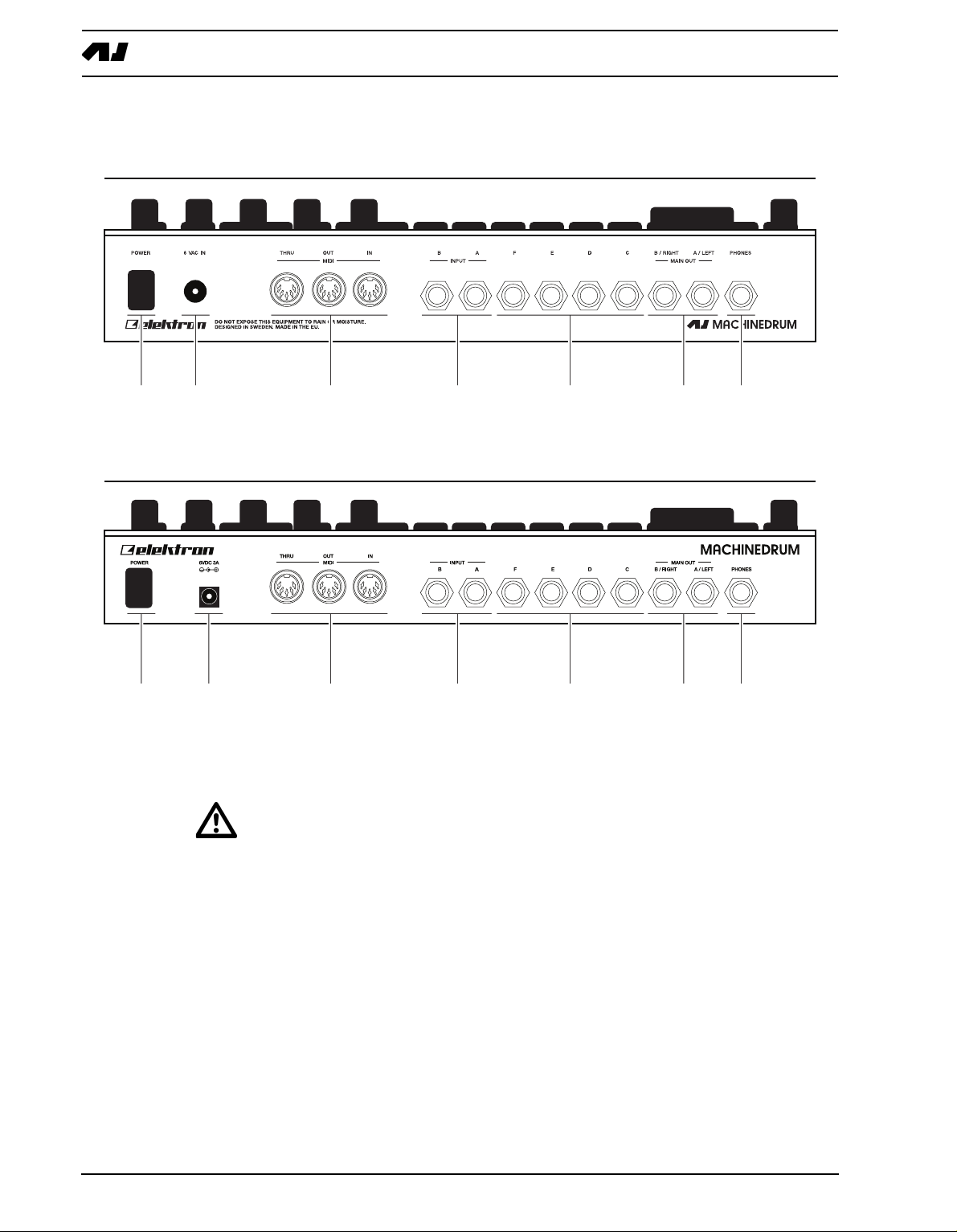
REAR CONNECTORS
The Machinedrum SPS-1 MKII/SPS-1UW MKII rear connectors:
1Power on/off switch.
2 6V DC power in.
•Caution! Use only an Elektron-approved power supply with your Machinedrum
SPS-1 MKII/SPS-1UW MKII A power supply is included with all MKII models It
can be used all over the globe without the need of voltage converters using an
appropriate power cord Using the wrong type of adapter may damage your unit
Damage caused by the use of incorrect power supply is not covered by warranty
Please see “TECHNICAL INFORMATION” on page 80 for details about the MKII
power supply
•Note that the MKI models require a different power supply compared to the MKII
models Please see “DIFFERENCES BETWEEN THE MKI AND MKII MODELS” on
page 81 for details about the power supply to be used with the MKI models
3 MIDI Thru.
4 MIDI Out.
5 MIDI In.
6 Input B.
&HEH"&$HEH"&JL'&)+",&'"&(-"&&("*&'&)+",&'"&(-"&&("*HEH"&B@>>$HEH"&JLB@>>

USER INTERFACE AND CONNECTORS
7
7 Input A.
8 Individual output F.
9 Individual output E.
10 Individual output D.
11 Individual output C.
12 Main out right / Individual output B.
13 Main out left / Individual output A.
14 Stereo headphones output.
RACK MOUNT KIT (ACCESSORY)
The Machinedrum SPS-1 MKII/SPS-1UW MKII can be rack mounted in a standard 19”
rack, using the Machinedrum rack mount kit which is ordered separately. When rack
mounted, the unit occupies four standard height units plus whatever additional space is
needed to accommodate cables plugged into the unit at the back.
RACK MOUNT KIT ASSEMBLY
Make sure that you have a Philips screwdriver which is in good condition, and which is the
right size. Use the included M3x6mm size screws to secure the rack mount consoles on
each side of the Machinedrum. Make sure that all screws are fastened for secure operation
of the unit.
CONNECTING THE UNIT
Before you start connecting the Machinedrum to other units, make sure that everything is
switched off.
1 Insert the supplied DC adapter into the wall socket, and connect the small plug into the
rear of the Machinedrum unit.
2 Connect the main out L/R from the Machinedrum to your mixer or amplifier.
3 If MIDI control is desired, connect MIDI OUT from the Machinedrum to the device that
you wish to send data to. Connect the MIDI IN to the device that you wish to receive data
from. The MIDI THRU port “echoes” the data arriving at the MIDI IN port, so it can be
used for chaining MIDI units together.
4 Switch on all units.
CARE INSTRUCTIONS
To ensure many years of trouble free operation, please follow the advice below:
•Never use any aggressive cleaners on the casing or the LCD overlay Remove
dust, dirt and fingerprints with a soft dry cloth More persistent dirt can be
removed with a slightly damp cloth using only water
•Never use sharp objects near the display to avoid scratches or damage Also
avoid applying any pressure to the display itself
•When transporting the Machinedrum, try to use the box and padding the Machine-
drum originally shipped with, or comparable packaging
•Make sure that you place the unit on a stable surface before use If you mount the
unit in a rack, be sure to tighten all four screws in the rack mount holes
•The memory used for storing patches and kits is powered by a battery inside the
unit It will hold data at least 6 years before needing replacement If the battery

USER INTERFACE AND CONNECTORS
8
needs replacement, the “BATTERY LOW” message will appear in the display Con-
tact Elektron support or your nearest repair center
•Turn off the machine when it is not in use

THE LCD USER INTERFACE
9
THE LCD USER INTERFACE
The center of Machinedrum SPS-1 MKII/SPS-1UW MKII editing is the LCD display. The
main interface screen is shown below:
1 The current tempo displayed with one decimal.
2 Four boxes showing the playback position in the pattern page.
3 The playback/recording status shown by the standard “record”, “play”, “pause” and
“stop” symbols; , , and .
4 Name and number of the current kit.
5 Specification of the MD-synth, machine and current data entry focus.
6 Level bar showing the overall volume level of the machine on the active track.
7 Up to eight control data entry values. They show what the DATA ENTRY knobs control
and also indicate the current data entry values. When two parameters depend on each
other in some way, they will have a small “clip” between them as shown below:
LAYER EDIT AND WINDOWS
When a function which puts a window on top of the main interface screen is opened, the
function of certain buttons and/or knobs will change. The buttons that are not used or
blocked can still be used to control the layer underneath. For example, when you have
called the tempo function it will make use of the SOUND SELECTION wheel, but you can
still use the DATA ENTRY knobs to control the track in focus. When a window has func-
tions mapped to such interface controls, help is provided at the bottom of the window in the
form of icons representing these controls. The icons are:
The arrow buttons The SOUND SELECTION wheel
The [FUNCTION] key The [TRIG] keys
•All windows can be closed using the [EXIT/NO] key

QUICK START
10
QUICK START
This quick start will guide you through some of the basic operations to allow you to start
using the SPS-1 MKII/SPS-1UW MKII right away. First connect it as described in section
“CONNECTING THE UNIT”, on page 7.
PLAYING AND TWEAKING DRUM SOUNDS
1 Press the [KIT] key.
2 Select the LOAD KIT icon in the menu and press [ENTER/YES]. You will now be pre-
sented with a list where you can select a kit name using the [UP] and [DOWN] keys.
3 Press [ENTER/YES] to load the kit. Exit the menu by pressing [EXIT/NO]
4 Now press any of the 16 [TRIG] keys to play the corresponding drum assigned to that
track. You will notice that the drum select LEDs in the upper left corner will light up
accordingly.
5 Turn the SOUND SELECTION wheel so that the <BD> LED is lit. <BD> is now the
“active track”, and every parameter that is being edited will be directed to the bass drum
track.
6 Make sure that the <SYNTHESIS> LED is lit by pressing the toggle key [SYNTHESIS/
EFFECTS/ROUTING].
7 Now, turn any of the DATA ENTRY knobs to tweak the corresponding bass drum
machine specific parameter. You can trigger the sound by pressing the first [TRIG] key
while you are turning the DATA ENTRY knob A to hear the pitch change.
•Instead of using the SOUND SELECTION wheel to choose the active track you can
hold the [FUNCTION] key while pressing the corresponding [TRIG] key
•The DATA ENTRY knobs have accelerated editing when pressed By default, the
knobs increase/decrease in steps of +1/-1 When pressed, the step length is
higher, allowing quicker adjustments
USING THE TRACK EFFECTS
1 Press the [SYNTHESIS/EFFECTS/ROUTING] key until the <EFFECTS> LED is lit.
2 You can now edit the track effect parameters for the active track by turning the DATA
ENTRY knobs.
SELECTING AND PLAYING A PATTERN
1 Make sure you have loaded a kit. See the previous section for details on this.
2 Press the [CLASSIC/EXTENDED] key until the <CLASSIC> LED is lit. You are now in
CLASSIC mode. The difference between CLASSIC and EXTENDED mode is explained
in more detail on page 35.
3 Check the [PATTERN/SONG] key so that the <PATTERN> LED is lit.
4 Press the [BANK GROUP] key to select between banks A to D or E to H. Select pattern
bank A to D for this demonstration.

QUICK START
11
5 To select pattern A01, press and hold the pattern selection key [A/E] and then the
[TRIG] key 1. You can see the currently selected pattern in the lower left corner of the
display.
6 To play this pattern, simply press the [PLAY] key. The pattern will start playing and will
loop once it reaches the end. Pressing the [PLAY] key while playing pauses the play-
back. Holding the [STOP] key and pressing [PLAY] will immediately restart the playback
from the beginning. The amount of <SCALE> LEDs lit indicated the number of pages the
pattern consists of. For example, if two <SCALE> LEDs are lit, then the pattern consists
of two pages.
7 To change pattern during playback, simply select a pattern the same way as in step 4.
The display will show the selected pattern beside the current one, but with an arrow
pointing towards it. This indicates that once the current pattern has come to its end, the
selected pattern will begin to play.
8 To stop the playback of the pattern, press the [STOP] key.
•There might be occasions when the Machinedrum keeps making noise after you
press the [STOP] button This situation can especially occur when using samples
with an infinite decay in the Machinedrum UserWave In order to force all the
tracks to go quiet, quickly press the [STOP] button twice
•The pattern page currently playing is indicated by the flashing of the <PATTERN
PAGE> LED
RECORDING A PATTERN USING GRID RECORDING
1 You can input notes into a pattern in the sequencer, both while it is playing or while it is
currently stopped. Press the [RECORD] key to start grid recording. The <RECORD>
LED will be lit the whole time during the process.
2 Select the active track using the SOUND SELECTION wheel.
3 Press the [TRIG] keys to insert 16th notes where you wish to have the machine trig-
gered. Pressing the same [TRIG] key once more removes the note.
4 To edit other tracks, change the active track using the SOUND SELECTION wheel.
SETTING THE ACCENT PATTERN
1 Hold [FUNCTION] and press key [B/F] to access the ACCENT screen.
2 On this screen you can set the accent level for all of the accent trigs. Use the SOUND
SELECTION wheel to set the level.
3 The accent pattern is shown on all <TRIG> LEDs above the [TRIG] keys as long as you
are in the accent screen. To accent a note, simply select it by pressing the [TRIG] key.
To remove the accent, press the same key again.
SETTING THE SWING PATTERN
1 Hold [FUNCTION] and press key [C/G] to access the swing screen.
2 On this screen you can set the amount of swing on notes selected by the swing pattern.
Use the SOUND SELECTION wheel to set the level. A level of approximately 65%
should allow you to hear the effect.
3 The swing pattern is shown on all <TRIG> LEDs above the [TRIG] keys as long as the
swing screen is active. The default swing pattern affects every other note, starting with

QUICK START
12
the second. The swing pattern can be changed using the [TRIG] keys, but for normal
rhythm styles the default pattern is better left as it is.
PATTERN LIVE RECORDING
1 The LIVE RECORDING mode of a pattern allows you to play the sounds in the kit while
the pattern is playing. To start this mode, hold [RECORD] and then press [PLAY].
2 You can now “play” all the machines in the kit directly on the [TRIG] keys. All played
notes will be quantised to 16th notes, and you will be able to hear them the next time the
pattern starts all over.
3 The pattern will loop until you press the [STOP] key.
PARAMETER LOCKS
1 Press the [CLASSIC/EXTENDED] key until the <EXTENDED> LED is lit. You are now in
extended mode. The difference between CLASSSIC and EXTENDED mode will be
explained on page 35.
2 Now it is possible to lock parameters to a specific note in the pattern. In GRID RECORD-
ING mode, hold a [TRIG] key and then tweak a parameter. The parameter adjusted will
be inverted on the LCD screen to indicate that it now is locked to the value you have set.
The corresponding <TRIG> LED will flash rapidly to indicate that a parameter is locked
for that step.
3 In LIVE RECORDING mode, you can lock parameters by tweaking the knobs while
recording.
4 Parameters can be locked for several tracks simultaneously. To lock parameters for a
new track, just repeat the sequence from step 2 above.
5 To remove a lock, enter grid edit mode and press the [TRIG] key on the locked note
twice. This removes the lock and restores the note to be triggered. You can also hold the
[TRIG] key while clicking the DATA ENTRY knob corresponding to locked parameter.
You will see that the inversion disappears and that the parameter lock is removed.
This manual suits for next models
2
Table of contents
Other Electron Recording Equipment manuals


