SERVICE MANUAL
8
4. PC FINAL ASSEMBLY BLK SB1
Ref. No. Part No. Description
1 SP-813027J PANEL MAIN SB1
2 SE-813036J WIND SEGMENT
3 SE-820327X SPACER SEGMENT
4 ZS-376521 BT BID30X08STL CMT
5 SW-812893J SW PUSH SB-221(METAL) 01-01
6 ZW-812439J SW120STL CMT
7 ZW-812440J PW122X160X050STL NI3
8 SP-812211J COVER BOTTOM (A)
9 SA-812237J FOOT
10 SK-812204J KNOB VOL
11 SK-813028J KNOB ENCODER
12 SK-813200J KNOB VOL D11.5
13-A }AX-812121X2 AC ADAPTER L8006 J (PLUG IN)
[J]
13-B }AX-812122X2 AC ADAPTER L8006 C,A (PLUG IN)
[A]
14 }AX-812123X2 AC ADAPTER L8006 E,V (CORD IN)
[E,V,B]
15 }EJ-428247N PLUG ADAPTOR ECPL01BKR5 BS5733
[B]
1. PC BOARD BLK SB1
Ref. No. Part No. Description
1 BA-L8014A020A PC(#) SB1 BLK SB1
PC(#) SB1 BLK CONSISTS OF FOLLOWING PC BOARDS
•PC MAIN BLK SB1
•PC DISPLAY BLK SB1
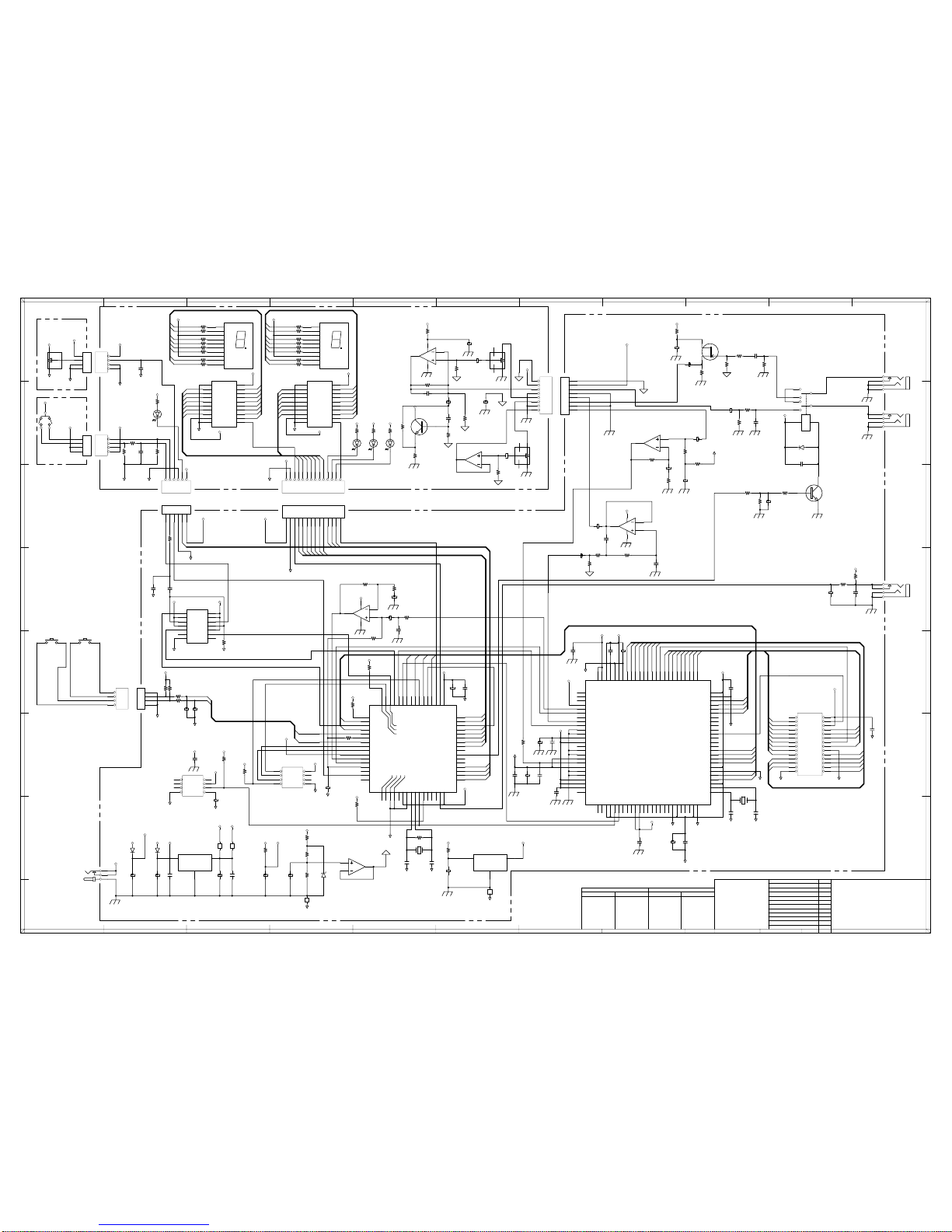
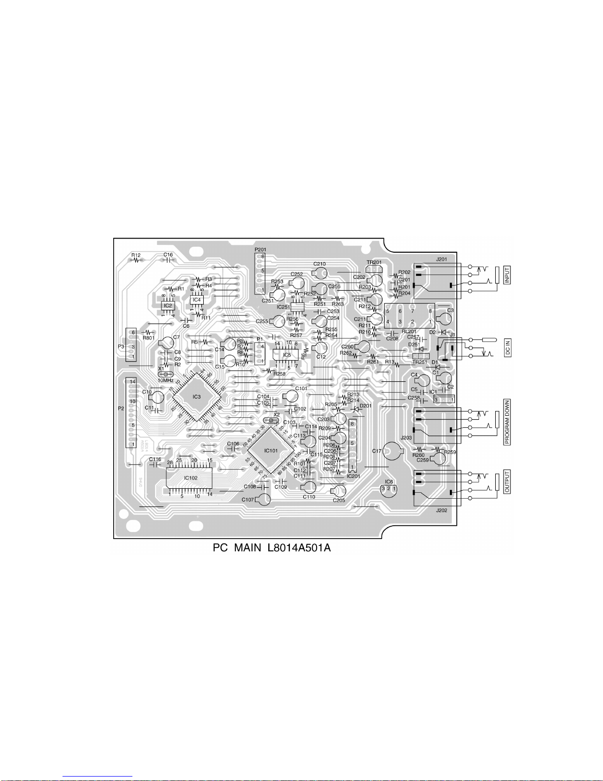
2. PC MAIN BLK SB1
Ref. No. Part No. Description
D1 ED-386225J D SILICON 1N4002 T26 100/1.0A
D2 ED-811455J D SILICON H 1SS133T-77 T26
D201 ED-393771J D ZENER H HZS5C1 T26
D251 ED-811455J D SILICON H 1SS133T-77 T26
D801 ED-811455J D SILICON H 1SS133T-77 T26
D802 ED-811455J D SILICON H 1SS133T-77 T26
IC1 EI-438318J IC NJM78L05AT1 T05
IC2 EI-431113J IC M51953BFP-73A FP73AT12E
IC3 EI-813039J IC HD6433640RA*** SB1-1
IC4 EI-813040J IC 93LC46AT-I/SN FP T08E
IC5 EI-428017J IC HD74HC74FP
IC101 EI-811878J IC AK7712AVT
IC102 EI-812883J IC HM6264BLFP-8LT
IC201 EI-403306J IC NJM4558L
IC251 EI-813022J IC NJU7032M FPT1T08
J1 EJ-812072J SOCKET DC HTJ-020-05A 1P
J201 EJ-812069J PHONE J HTJ-064-13H 6.3
J202 EJ-812069J PHONE J HTJ-064-13H 6.3
J203 EJ-812069J PHONE J HTJ-064-13H 6.3
RL201 EQ-813041J RELAY SIG RY-12WK 1TR 12V
TR201 ET-842477J TR FET 2SK2880 C,D,E T05
TR251 ET-362209 TR 2SC3330 S,T,U T05
X1 EI-812885J OSC X’TAL HC-49/U 10000KHz
X2 EI-811908J OSC X’TAL HC-49/U 18432KHz
3. PC DISPLAY BLK SB1
Ref. No. Part No. Description
100 SE-812672J SPACER LED L=8.5
200 SE-812673J SPACER LED L=12
D401 ED-812087J D LED L-934SRD-G RED
D402 ED-812086J D LED L-934SGD GREEN
D403 ED-813021J D LED L-934SYD YELLOW
D404 ED-812087J D LED L-934SRD-G RED
D405 ED-812088J D LED SA56-11SRWA
D406 ED-812088J D LED SA56-11SRWA
IC301 EI-403306J IC NJM4558L
IC401 EI-811085J IC HD74HC574FP
IC402 EI-811085J IC HD74HC574FP
TR351 ET-362209 TR 2SC3330 S,T,U T05
VR301 EV-812887J VR ROTARY RK09L1140 L12.5 A104
VR351 EV-812887J VR ROTARY RK09L1140 L12.5 A104
VR501 EV-813047J VR RT.RK0971110 L15 11D B103SP
SW601 ES-813048J SW ROTARY ENCODER EC11B202 L15