5. Setting DMX signal reception (reserved for installer)
manual system 6 is able to control both dimmers and fixtures via DMX.
For your benefit, we explain below how to operate 2 different DMX controllable devices, a standard DMX controllable fixture
and a coemar comet.
All fixtures should be addressed to the channel DMX 1 to respond correctly to the 6 channels of the manual system 6,
many fixtures require different methods for doing this, we recommend that you refer to the respective owner’s manuals.
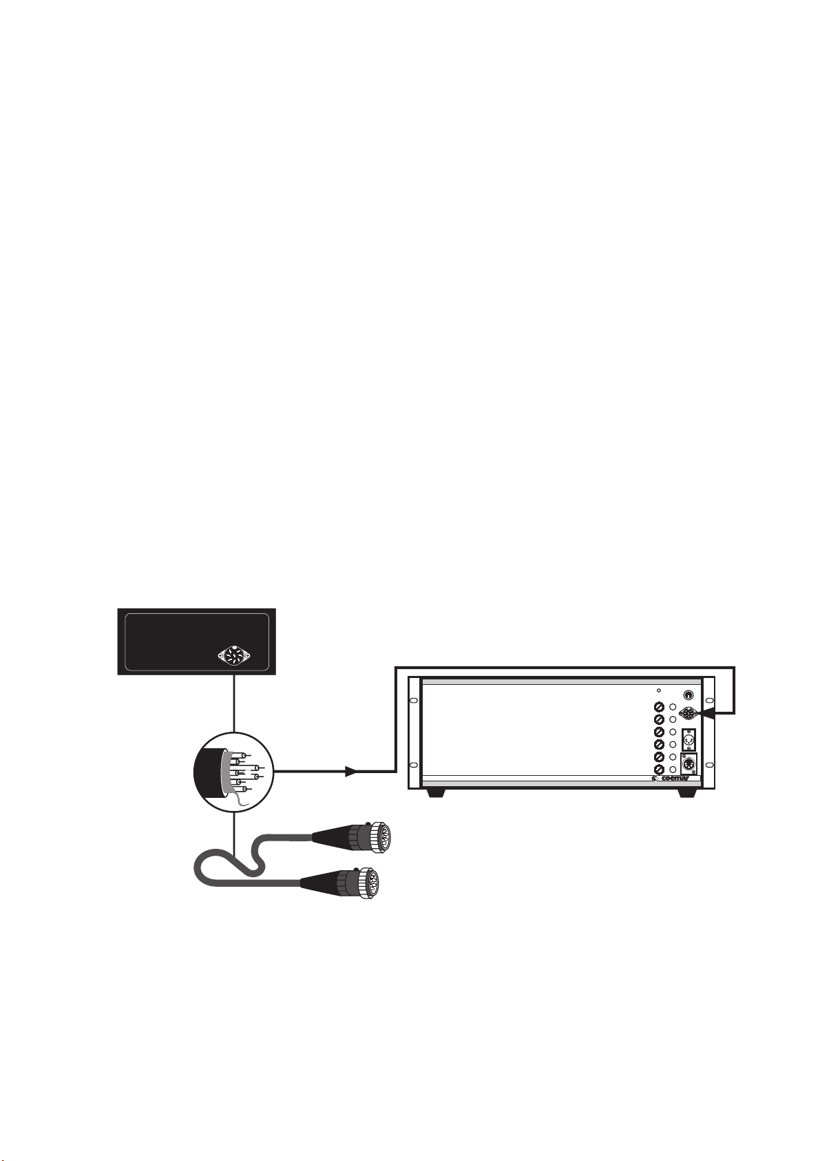
5.1. coemar DIGIfactor 6 channels
1-At start-up, the display on your projector will show A001 indicating the address DMX 1.
This address should be maintained to ensure correct functioning
In the case that the display should show otherwise, proceed as follows:
Press the +or -buttons until the display shows DMX A001 , the display will flash, indicating that the address is not recor-
ded.
2- Press the enter button to record your selection, the display will cease flashing and the fixture will respond to address DMX
1.
holding down the + or - will allow for rapid scrolling through the display.
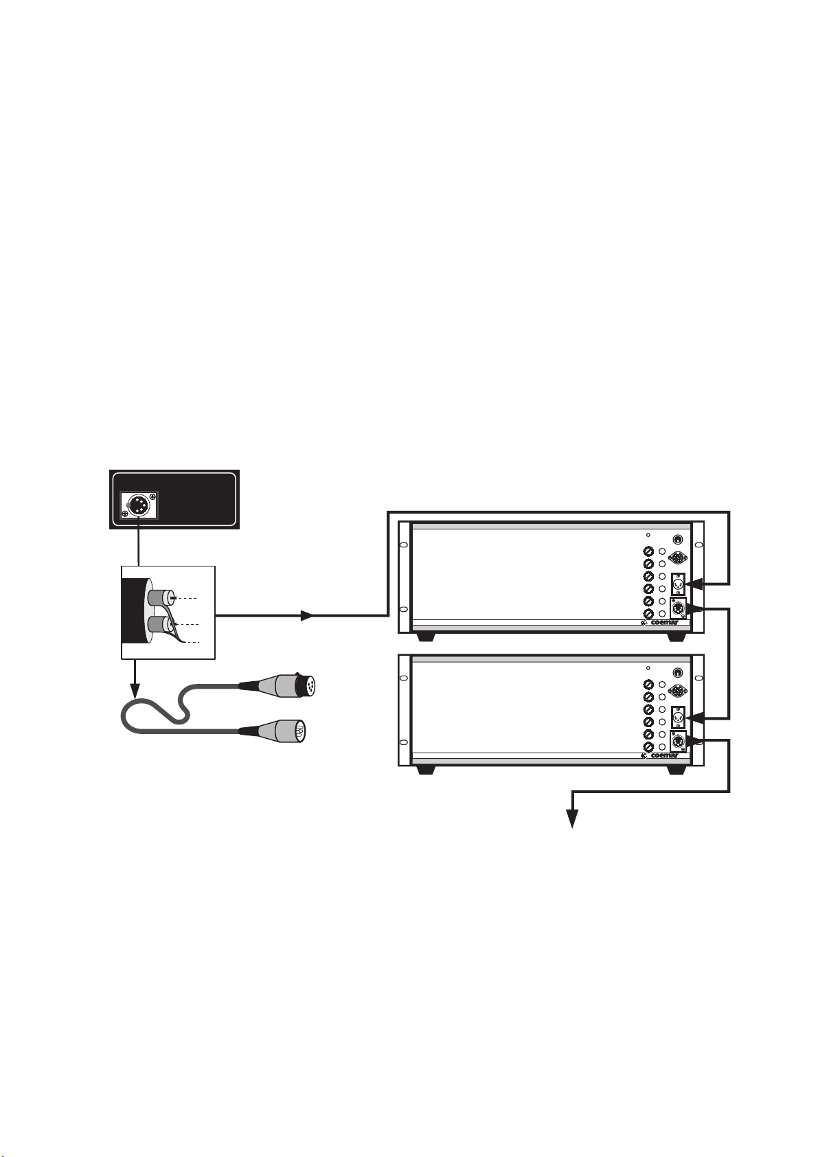
5.2. coemar comet
It is important to set the dip switched correctly to ensure correct reception by the comet.
The comet should be set, in fact, as would any other DMX 512 unit attached to the manual system 6, to address 1
The following diagramme shows only the dip switches which should be set to 0N.
Other comets with the same address setting can also be controlled; if you wish them to be synchronised, you will need to also
connect the stereo jack between comets; for other information refer to the comet manual.