Electronics Line EL-2662 User manual

EL-2662
The EL-2662 is a gas alarm with an integrated transmitter designed for use with Electronics Line 3000’s supervised wireless range
of receivers. On detecting the presence of gas, the unit sounds an alarm and notifies the control panel.
The gas alarm has been designed to detect and provide early warning of the presence of natural (methane) and LP (propane, butane)
gases. The gas sensor has been calibrated to detect these combustible gases at concentrations below 15% of the L.E.L (Lower
Explosive Limit) – the level at which an air-gas mixture becomes explosive. Methane has an L.E.L. of 3.8%. Propane 2.1% and Butane
1.69%. (Source: UL 1484 Standard for Safety – Residential Gas Detector). The sensor detects methane at concentrations in excess of
0.5% and propane/butane at concentrations in excess of 0.503%.
IMPORTANT: Gas appliances should be installed or serviced by authorized personnel only. Always remember to close all gas-
operated household appliances when not in use. Familiarize your family with the alarm signal and instruct them on what to do
in the event of an alarm. The EL-2662 should be used as an integral part of a comprehensive safety program including
appropriate home, office and life insurance. The manufacturer makes no claim regarding the health hazard of gas and/or the
alarm’s ability to protect the user’s health in any way.
Mounting Location
The EL-2662 gas alarm will only function effectively if installed in the correct location.
Consider the following before mounting the gas alarm:
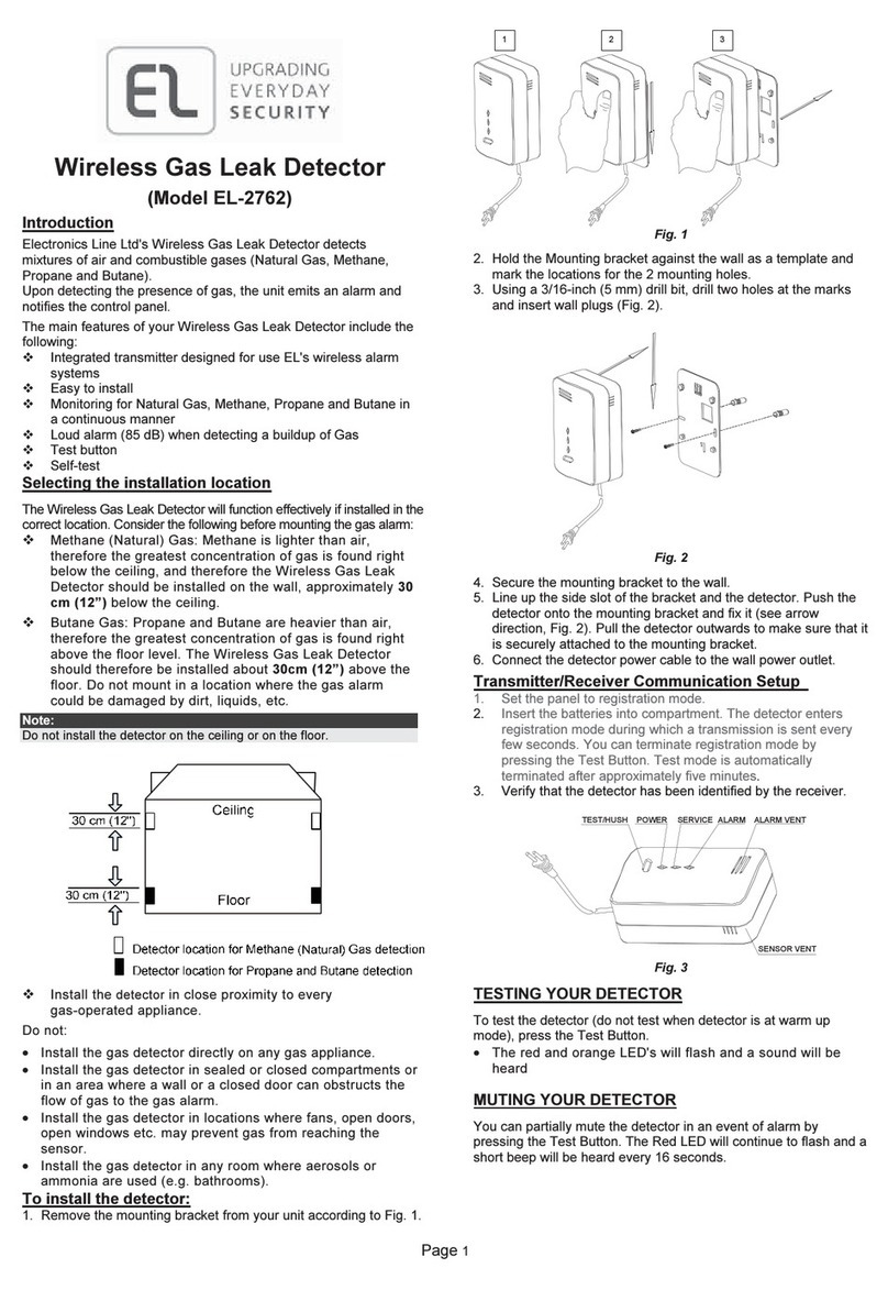
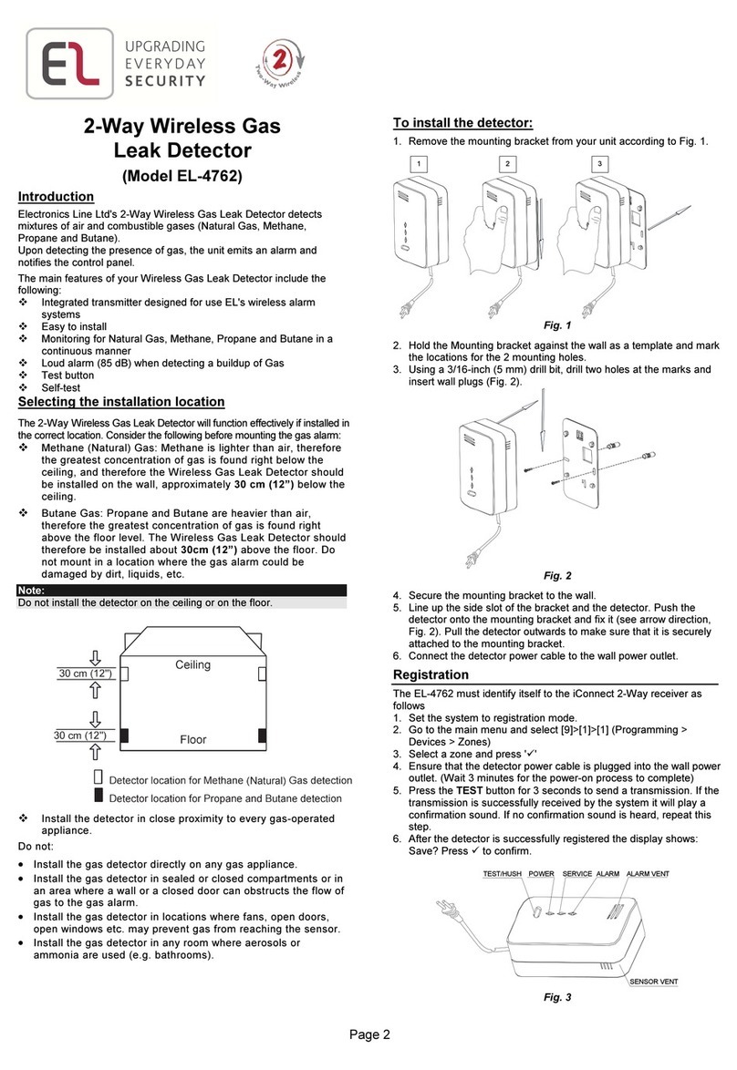
• Choose a mounting location according to the following guidelines:
o Methane (Natural) Gas: Since Methane is lighter than air, the greatest
concentration of gas will be immediately under the ceiling. The EL-2662
should therefore be installed on the wall about 15-20cm (6-12”) below the
ceiling. Do not install the gas alarm on the ceiling. If the ceiling is higher
than 2.6m (8’) or non-standard (e.g. sloped or gabled), seek advice from
your local gas company regarding the optimal mounting location.
o Butane Gas: Since Propane and Butane are heavier than air, the greatest
concentration of gas will be at floor level. The EL-2662 should therefore
be installed about 10-15cm (4-6”) above the floor). Do not install the gas
alarm on the floor. Do not mount in a location where the gas alarm could
be damaged by dirt, liquids, jolting etc.
• Install the gas alarm in close proximity to every gas-operated appliance.
• Do not install the gas alarm directly on any gas appliance.
• Do not install the gas alarm in sealed or closed compartments or in an area where a wall or divider obstructs the flow
of gas to the gas alarm. Anything obstructing the sensor could delay or prevent an alarm activation. An EL-2662 gas
alarm installed in the basement may not detect a gas leak on the first or second floor. A closed door may also prevent
gas on one side from reaching the sensor on the other side.
• Do not install the gas alarm in locations where drafts or breezes (from fans, open doors, open windows etc.) may
prevent gas from reaching the sensor. The gas alarm will only detect gas in closed spaces when a significant amount
of gas has reached the sensor.
• Do not install the gas alarm in any room where aerosols or ammonia are used (e.g. bathrooms).
Installation Instructions
Figure 2: EL-2662 (cover off)
1. Release the four screws on the back panel of the unit and remove the top cover.
2. Apply battery power to the transmitter board by removing the dividers separating the battery from the contacts on the
battery holder. Note: Due to the occurrence of voltage delay in lithium batteries that have been in storage, the batteries may
initially appear to be dead. In this case, leave the unit in Test mode for a few minutes until the battery voltage level is stabilized.
3. Install the Test jumper; the Transmission LED flashes slowly.
Internal
Sounde
r
Battery
Holder
Test
Jumper
Wire
Brace
Gas
Senso
r
Transmission
LED
Power LED
Figure 1: Mounting Location
12V
Power Input

4. While the EL-2662 is in Test mode, set the receiver to Registration mode and wait for the receiver to indicate that the
transmitter has been registered successfully. Write the number of the zone and the transmitter number (if applicable)
on the sticker provided. Affix the sticker inside the front cover for future reference. Note: Alternatively, the EL-2662 can
be registered to the receiver by manually entering the transmitter's serial number.
5. Remove the Test jumper and place it over one pin for storage. Test mode is limited to four minutes. After the four
minutes have expired, the detector switches back to normal operation. If this happens, you can reset Test mode by
removing and replacing the Test jumper.
6. Choose a mounting location according to the guidelines in the previous section.
7. Test the transmitter to determine the suitability of your chosen mounting location. To do so, place the transmitter in the
exact mounting position and insert the Test jumper making certain that the transmissions are successfully received. If
necessary, relocate the transmitter to a better position and repeat the test. After testing, remove the Test jumper and
place it over one pin for storage.
8. Connect a 12V AC-DC transformer to the power input terminal block (J6) (polarity is not important). Thread the
transformer’s wires via the wire brace and tighten the two screws for strain relief.
9. Close the top cover with the transformer’s wires protruding from the unit (there is a small notch in the cover adjacent to the wire
brace that is intended for this purpose). Ensure that the Power LED is inserted properly into place.
10. Attach the EL-2662 to the wall with the supplied screws.
11. Connect the transformer to an AC outlet. The green LED indicator provides a
permanent indication that the EL-2662 is receiving power. Please note that the
EL-2662 only starts operating (i.e. detects gas) approximately 15 minutes after
power is applied. Note: During normal operation, both the detector and transmitter
are powered by the 12V power source. The 3.6V battery provides backup to the
transmitter only and the EL-2662 will not detect gas if the 12V power source is cut off.
Maintenance and Testing
The EL-2662 comes pre-calibrated and requires no further adjustments. Once a month, clean
around the area of the unit with a vacuum cleaner or soft brush. The gas alarm can be tested
using a butane cigarette lighter as a gas source. Position the lighter’s gas nozzle close to the
front of the detector. Without rotating the flint wheel, press the lighter’s gas release button for a
few seconds; the detector is activated and the buzzer sounds. Make certain the alarm can be
heard by all those who are meant to hear it. When the gas dissipates, the detector returns to
standby mode. Alternatively, the gas alarm can be tested by holding a piece of cotton wool
dipped in alcohol (not to wet!) close to the front of the detector.
What to do when Gas is Detected
When gas is detected, a rapid beeping indicates the alarm condition (one beep per second) and the EL-2662 notifies the
control panel of the detection.
• Extinguish all flames (cigarettes, pilot lights etc.).
• Open doors and windows.
• Do not touch any electrical switches.
• Do not unplug the EL-2662 gas alarm.
• Turn off the main gas valve and leave the
premises.
• Re-enter the premises only when the alarm stops
beeping, the odor clears and/or the gas company
indicates that it is safe.
Troubleshooting
Trouble Signal – The EL-2662 gas alarm emits a trouble signal (one beep per 5 seconds) under the following conditions:
a) The voltage is lower than required. Check your outlet by plugging in another appliance and checking its operation. If the
outlet is not faulty and the gas alarm does not respond to the lighter test, replace the unit.
b) The sensor has malfunctioned – replace the unit!
c) The green Power LED is off. If the unit responds to the lighter test, the LED is burnt out – replace the unit!
False Alarms – If the alarm is activated in response to non-gas fumes (alcohol, hairspray, deodorant, paint, thinner, cleaning
fluids etc.) make certain to thoroughly ventilate the area.
Technical Specifications
Operating Voltage: 12VDC
Transmitter Backup: 3.6V ½ AA Lithium Battery
Caution: Fire, explosion and severe burn hazard!
Do not recharge, disassemble or heat above 100°C.
Current Consumption: 25mA (alarm), 10µA (standby)
Antenna: Built-in Internal Whip
Transmitter Frequency: 868.35, 433.92 or 418MHz FM
Transmissions: Alarm, AC Loss, Low Battery, Supervision
Gases Detected: Methane, Propane, Butane
Audible Alarm: 85dB at 3m
Operating Temperature: 0-50°C
Electronics Line 3000 Ltd.: 2 Granit Street, Kiryat Arieh, POB 3253, Petah Tikvah 49130 Israel. Tel: (972-3) 918-1333, Fax: (972-3) 922-0831
USA: 5637 Arapahoe Avenue, Boulder, Colorado 80303. Tel: (800) 683-6835, Fax: (303) 938-8062
UK: Unit 7, Leviss Trading Estate, Station Road, Stechford, Birmingham B33 9AE. Tel: (44-121) 789-8111, Fax: (44-121) 789-8055
France: ZI-61, rue du Marché Rollay, 94500 Champigny-Sur-Marne. Tel: (33-1) 45.16.19.20, Fax: (33-1) 45.16.19.29
ZI0363B (4/05)
A
ll data is subject to change without prior notice. In no event shall Electronics Line 3000 Ltd. (EL3K) be liable for an amount in excess of EL3K.’s
original selling price of this product, for any loss or damage whether direct, indirect, incidental, consequential or otherwise arising out of any failure o
f
the product. Hereby, Electronics Line 3000 Ltd. declares that this sensor/transmitter is in compliance with the essential requirements and othe
r
relevant provisions of Directive 1999/5/EC.
Figure 3: Lighter Test
Table of contents
Other Electronics Line Gas Detector manuals
