ENMET eGC User manual

“eGC” Quick Guide Rev. 2
1
“eGC”
USER’S QUICK GUIDE
Rev. 2
1 March 2021
eGC Technical Support
(270) 745-0099

“eGC” Quick Guide Rev. 2
2
PURPOSE
This guide provides basic set-up and operating instructions for the ENMET “eGC” trace VOC
monitoring system.
GENERAL INFORMATION
The “eGC” is designed to automatically perform repetitive measurements of trace level (i.e., ppbv)
concentrations of benzene and other VOCs in ambient air.The VOC analyzer is based on a
miniaturized, temperature-controlled gas chromatograph. The basic eGC also contains a data-
logger connected to a GPS module that provides accurate location and time information along
with archived measurement data. Measurement data are automatically transmitted via an on-
board cellular data modem to ENMET’s internet-based web server where the data can be viewed,
archived and retrieved. The eGC performs one measurement every 10 minutes.
The eGC external enclosure protects the instrument from the environment. A fan inside the
enclosure draws in a large volume of ambient air to cool the device and to provide a
representative ambient air sample to the inlet of the analyzer. The mini-GC “engine” analyzer is
housed in a separate internal enclosure that is temperature controlled using a thermoelectric
cooler/heater (TEC). This arrangement allows accurate, reproducible measurements to be made
regardless of ambient temperature fluctuations.
Ambient air samples are collected at a flow rate of approximately 250 sccm for a period of 45
seconds and then injected from a thermally desorbed sample collector into a gas chromatograph
for analysis. The resulting chromatogram and associated measurement data reports are then
transmitted to the web-server.
The eGC can be configured for either 12VDC or 120VAC power. The low power consumption of
the eGC (< 60 Watts) makes solar-powered operation an attractive option.
The performance of the eGC can be enhanced by a variety of optional accessories, including:
• A sun-shade to limit exposure to direct sunlight.
• A wind speed/direction sensor
• A solar panel & battery power supply
• An elevated “Sample Inlet Snorkel” for unobstructed, 360° sampling
• A “Calibration Box” to supply scrubbed air and calibration gas to the eGC
• A “Continuous Sampler” accessory to allow ambient air samples to be collected 100%
of the time, without interruption
Regular calibration of the eGC is accomplished using compressed calibration gas supplied either
from an external, certified calibration gas cylinder (e.g., benzene @ 10 ppb) or, from the
“Calibration Box” accessory. The system has a built in flow meter to permit easy field adjustment
of the calibration gas flow (i.e., 400 sccm). Multiple daily calibrations (e.g., 6 hour intervals) are
recommended for highest accuracy.
UNPACKING AND INITIAL SET-UP

“eGC” Quick Guide Rev. 2
3
The ENMET eGC is typically shipped in two pieces to minimize the possibility of shipping damage.
(
It is recommended to save the eGC shipping containers.
) The largest piece is the external plastic
enclosure box. The other piece is the internal GC “engine” box. Opening the exterior enclosure
reveals a space, defined by four (4) screw holes, where the GC engine will be mounted (figure 1).
Figure 1.eGC Exterior enclosure box layout

“eGC” Quick Guide Rev. 2
4
The GC “engine” is the smaller metal box with two metal mounting brackets that have holes that
line up with the four screw holes in the enclosure mounting plate (fig. 2).
Figure 2.eGC “engine” box
Figure 3.eGC engine installed into the exterior enclosure.

“eGC” Quick Guide Rev. 2
5
Carrier gas for the gas chromatograph is derived from scrubbed ambient air. The scrubber is
attached to a bracket inside the enclosure door using a Velcro strap (see figure 4). The indicating
Drie-Rite™ appears to be BLUE in color until it is saturated with water, whereupon it turns PINK.
The scrubber is functional until there is no longer any blue color showing in the scrubber.
Figure 4.eGC external scrubber location. Remove caps. Connect charcoal end to eGC
NOTE: Failure to connect the external scrubber, or, failure to replace a depleted scrubber can
result in significantly shortened operating life of the eGC.
There are no other “user serviceable items” in the eGC. Call ENMET for all service issues.

“eGC” Quick Guide Rev. 2
6
SET-UP PROCEDURE
STEP 1. Install the eGC “Engine” into the exterior enclosure box.
Attach the eGC engine to the enclosure using four (4) flat-
head Philips screws (supplied).
STEP 2. Locate the (4) mounting holes near the fan grill on the side of the eGC
enclosure. Attach the plastic fan vent cover using (4) 4-40 x ½” Philips
head screws (supplied). Make sure that the fan vent cover opening is
oriented toward the bottom of the enclosure.
(NOTE: The eGC is designed to be mounted vertically (e.g., on a wall or pole) outside
to prevent rain from entering the enclosure.)

“eGC” Quick Guide Rev. 2
7
STEP 3. Make sure the carrier gas scrubber cartridge is installed into the door
bracket using the Velcro strap (see figure 4).
STEP 4. Connect the plastic male Luer fitting on the carrier gas inlet tubing to the
female Luer fitting on the bottom of the external scrubber cartridge Luer
fitting as shown below:
STEP 5. Connect the DB-25 power I/O cable to the “engine” box as shown below.

“eGC” Quick Guide Rev. 2
8
STEP 6. Connect the thermoelectric cooler power cable.
STEP 7. Insert the thermocouple from the data logger into the fitting on the top
of the eGC engine box. The thermocouple must be inserted until stopped
by the black heat-shrink on the wire

“eGC” Quick Guide Rev. 2
9
STEP 8. Connect the 1/8” tubing from the calibration gas flow meter to the
calibration gas inlet fitting of the eGC. Make sure the 1/8” Swagelok
fitting is tight to prevent leakage of the calibration gas.
(NOTE: Ambient air samples are introduced into the eGC at a 1/4”
Swagelok™ “SAMPLE INLET” fitting located at the upper left hand corner
of the eGC Engine enclosure. The Sample Inlet block provides a TEE
connection that allows pressurized samples (e.g., from an external gas
source) to be connected to the eGC without fear of over-pressurization of
the sample inlet. Gas flowing into the ¼” Swagelok fitting is immediately
vented to a port on the side of the inlet block. When the eGC is ready to
collect a sample, it simply pulls in a side-stream sample from the TEE at a
flow rate of about 250 sccm. The recommended flow rate for externally
applied samples is 400 sccm to 1,000 sccm.)
A “floating-ball” flow meter is provided inside the eGC enclosure to
provide verification that the 5 psi calibration gas source is providing at
least 400 sccm of calibration gas flow to the eGC SAMPLE INLET while the
cal gas solenoid valve is activated during the 45-second sampling period
of the calibration cycle.
This completes the initial set-up of the eGC hardware prior to normal operation.

“eGC” Quick Guide Rev. 2
10
“NORMAL” OPERATION
1. If the (optional) cellular data modem is being used, then verify that the antenna for the
cellular modem is securely attached to the connector on the top of the eGC enclosure as shown
below:
2. If the unit is configured for 120V AC Power, then plug the power cable into the power
cord connector on the power entry module at the bottom of the eGC. Plug the other end into
a 120VAC wall power receptacle.

“eGC” Quick Guide Rev. 2
11
3. If the unit is configured for 12V DC Power, then plug the DC power cable into the
2-pin circular connector on the power entry module at the bottom of the eGC.
Connect the other end to a source of 12V DC power (e.g., a car battery, 12VDC power
supply or solar panel power module).(Maximum current draw is 7 Amps.)
4. If using the (optional) eGC Wind Sensor accessory, then plug the Wind Sensor cable
into the 6-pin circular weather station connector. Verify that the Wind Sensor is properly
mounted in the clear and oriented to a known reference direction.
5. Connect the 1/8” calibration gas inlet Swagelok fitting on the power entry plate to a 10
ppb calibration gas cylinder (or the “Calibration Box” accessory) using a length of 1/8” OD, pre-
cleaned, stainless steel (SS) tubing.
6. If using a (user supplied) calibration gas cylinder and a (user supplied) 2-stage
pressure regulator then begin by securing the pressure regulator to the cylinder. Ensure
that the regulator outlet valve (i.e., “VALVE 2” in the figure) is closed.
7. Turn the pressure adjustment knob counterclockwise until it stops with gentle
pressure. Turn on the “MAIN” valve on the cylinder and turn the pressure
adjustment knob slowly clockwise to adjust the second-stage pressure to 5 psi. Open
“VALVE 2”. Use the pressure adjustment knob to increase pressure to 5 psi if it drops after
opening “VALVE 2”.
8. Test the calibration gas delivery system for leaks. Close the “MAIN” valve on the cylinder
and note the pressure on the high pressure gauge. Wait 5 minutes and check the high-pressure

“eGC” Quick Guide Rev. 2
12
side pressure again. If the high-pressure side needle has dropped during the 5 minute
wait period then there is a significant leak in the system and calibration gas will be lost over time.
If this occurs, check all Swagelok connections for tightness and check for leaks again by closing
the cylinder “MAIN” valve and waiting to see if there is pressure loss on the high
pressure gauge. If there is no pressure loss, open the “MAIN” valve on the cylinder.
(NOTE: Swagelok fittings should not be over-tightened. Tighten the nut with a wrench
by not more than ¾ of a turn after finger-tight.)
(NOTE: The second stage pressure can be adjusted up or down by a few psi (if
needed) to maintain a flow of about 0.5 LPM (as observed on the flow meter inside
the enclosure) during the 45-sec sampling period of the calibration run.)
(It is extremely important that the second-stage pressure be maintained below 20 psi
or the calibration gas solenoid valve will leak and the calibration gas cylinder will be drained
prematurely.)
“MAIN”
Valve
“VALVE 2”
Pressure
Adjustment
Knob

“eGC” Quick Guide Rev. 2
13
9. Turn “ON” the eGC power by pressing the power button located on the power entry
module. The GC will then display a start-up screen with the version number of the internal
firmware. The eGC will begin collecting air samples for analysis at 10-minute intervals beginning
at the nearest start time on the clock (i.e., at 0, 10, 20, 30, 40 or 50 minutes after the hour). The
first few readings will be invalid until the instrument has warmed-up (e.g., for 30 minutes) to reach
its operating temperature.
(NOTE: Wait at least 30 seconds after turning the eGC OFF before turning it ON again
or the current surge may blow the 120VAC fuse on the AC power inlet.)
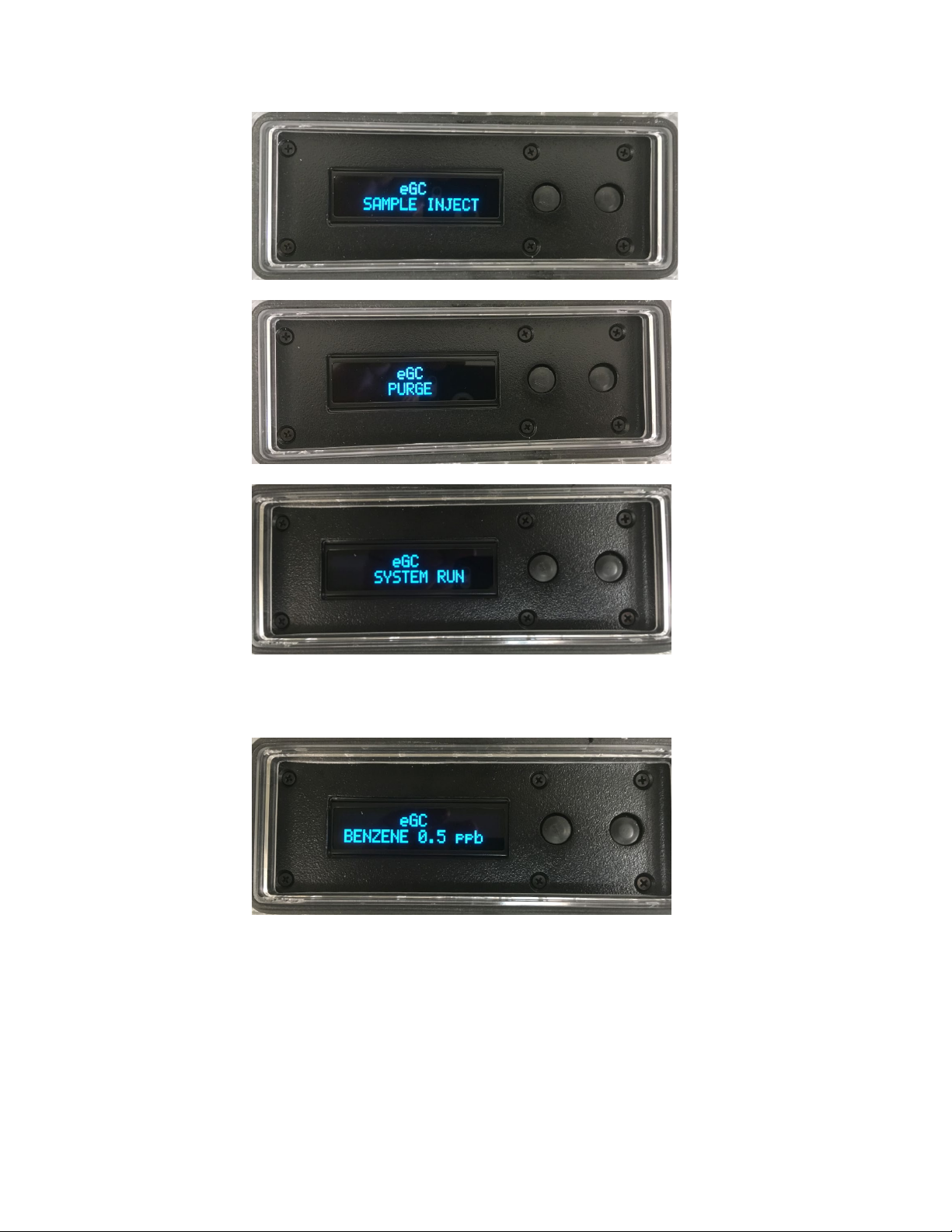
10. The eGC will display the following messages during the measurement cycle:
“eGC” Quick Guide Rev. 2
14
When the measurement is complete then the results will be displayed until the next
measurement begins.

“eGC” Quick Guide Rev. 2
15
11. Calibration of the eGC will occur at pre-programmed intervals. The eGC is pre-set
to calibrate 4 times every day (i.e., at 0000, 0600, 1200 and 1800 GMT).
“Calibration” consists of the eGC energizing a small solenoid valve on the sample inlet
block to turn on the flow of calibration gas. The measured GC peak height of the
calibration gas(es) is used to adjust a detector response factor that corrects the reported
concentration readings for periodic drift of the eGC.
A calibration can be initiated manually by pressing the right-most button adjacent
to the eGC display.
The button is only active when the eGC is in idle mode,
displaying results at the completion of a run as shown below
:
The default concentration for the eGC calibration gas is 10.0 ppbv. If your
calibration gas cylinder is certified to a different concentration, then the default
concentration can be adjusted using the procedure described in Step #12 (below).
Manual calibrations should only be attempted after the eGC has been fully warmed-up.
12. To adjust the default setting of the calibration gas concentration follow these steps:
a) Turn OFF the eGC. Press and HOLD the “MEASURE” button. Turn ON the
eGC power. The eGC will display the current setting of the calibration gas
concentration value.
b) To increase the value, press the “MEASURE” button. To decrease the
value, press the “CALIBRATE” button. Press the button as many times as needed
to arrive at the concentration of your certified gas standard.

“eGC” Quick Guide Rev. 2
16
c) After 10 seconds of inactivity, the entered value will be accepted and the
eGC will resume operation.
d) If the eGC has been configured to measure multiple vapors (e.g., BTX)
then after 10 seconds has elapsed the display will show the concentration
of the next calibration vapor (e.g., toluene). This value can be changed
as described previously.
e) This process will continue until the concentrations of all of the calibration
vapors (e.g., benzene, toluene, and xylene) have been updated.
13. It is strongly recommended that following initial un-packing and set-up, that the eGC be
turned on and stabilized for 24 hours prior to accepting the reported vapor concentrations as
valid. This allows contaminants commonly associated with shipment of the eGC to be
thoroughly purged from the system.
Table of contents
Other ENMET Gas Detector manuals


Popular Gas Detector manuals by other brands

Atest Gaz
Atest Gaz Teta EcoWent user manual

Eagle Eye Power Solutions
Eagle Eye Power Solutions GD-3000 user manual

RC Systems
RC Systems SenSmart 2000 installation guide

Spectrex
Spectrex SafEye Quasar 950 User and maintenance manual

BRUEL & KJAER
BRUEL & KJAER 1306 instruction manual

Cosmos
Cosmos XP-704 III instruction manual


