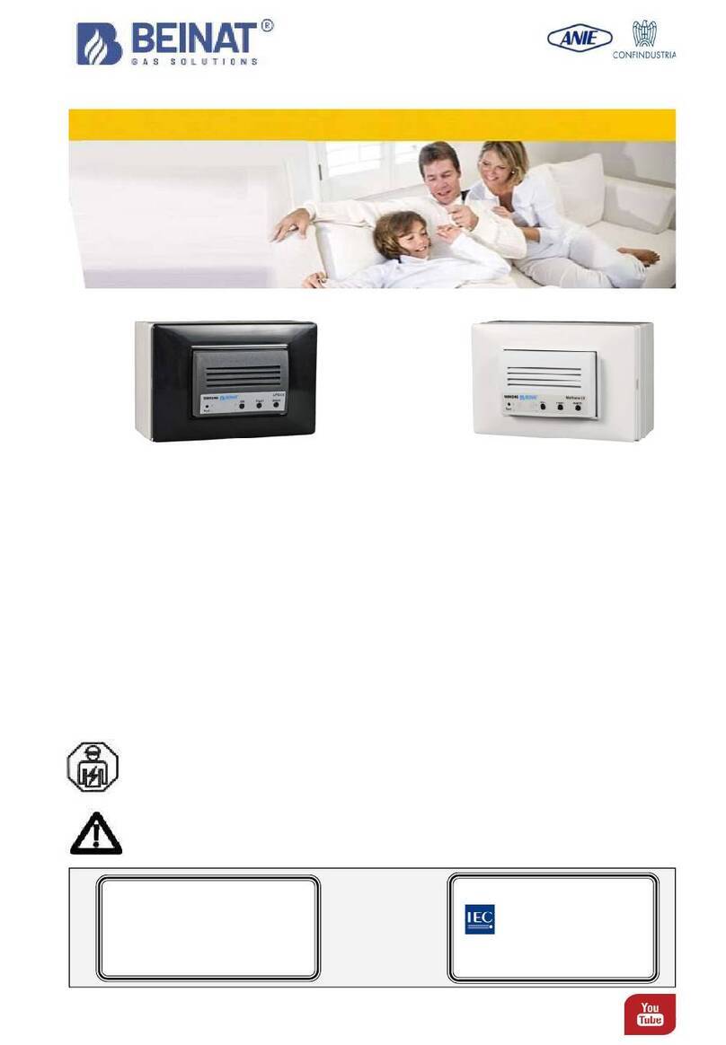
BEINAT BXI32 User manual

Channel: Beinat gas solutions
Belonging to
Gas control unit 32 addressables digital sensors BXI32
Rev. 1-14
Installationand
user guide TO INSTALL IN
SAFE ZONENO ATEX
The experience and the knowledge
acquired over the years within industrial
sector and market together with the
prestige that has always made BEINAT
S.r.l. have allowed the design of a new
Gas Control Unit the... “BXI32”
which has the prerogative to control,
through the connected addressed
sensors to it from 1 to 32, the presence
of gas: Toxic, Explosive, and Oxygen
The control unit BXI32 has been designed
and built to meet the current
requirements of the Market and in
compliance with European Standard for
checking gas presence in a versatile and
innovative with addressed sensors
through an addressed network RS-
485 MODBUS
When one of the connected sensors exceeds the pre-alarm setpoint, the control unit emits a proportional sound
signal, based on the amount of gas detected, and shows on the display the number of the sensor, the amount
of gas detected and its origin; the alarm triggered is saved in a memory (Datalogger).
The control unit is equipped with 1 general alarm relay with/without Positive Safety to enable further
independent control of two solenoid valves..
Up to 2 relay expansion cards CARD-TX4R can be inserted if nedessary.
> Self-diagnosis of the whole system with detections
Alarms, faults, transmissions, malfunctions, etc.
> Data Logger storage 50 episodes
> Ordinary maintenance program
>AlarmsSource
> Automatic reading of the gas type of each sensor
> Adjustable alarm level for each sensor.
> Automatic operating range from 20 to 100% LEL
> Efficiency of the connected sensors
>Positive Security Function
> Possibility of inserting Relay expansion card
> Factory reset
> Connection, Printer to print the Reports
> Manual alarm button connection
> Brand
>Serialnumber
> Date and Time
> Monitored sensor
> Graph of the quantity of gas detected
Some main
FEATURES
The first with self-diagnosis
and Maintenance Program
Electric connections also available on
Important: Assembly / maintenance of the appliance must be carried out by qualified personnel
and in accordance with applicable laws and regulations.
The manufacturer assumes no responsibility for the use of products that have to comply with
particular environmental and / or installation standards.
Important note
Before connecting the equipment, it is recommended that you read the instruction manual carefully
and keep it for future reference.
It is also recommended to perform the electrical connections correctly as per enclosed drawings,
observing the instructions and the Standards.
N.B. Refer to the documentation in all cases where the symbol is on the side
CONFORMITY EN 50194
EN 45544-1-3
EN 61010-1
Compliant EN 60079-29-1
Installation EN 60079-29-2
EN 50270
Reports issued by TUV Italia

Page 2
Technical features
Main features
Optional cabinet for BXI32, composition:
a) Rail DIN Omega for insertion BXI32,
b) Switching Power Supply 110/230 VAC 35W 12 VDC
c) Control unit cable and power supply,
d) Battery holder bracket
Dimensions: 340x280x160
Degree of protection: IP65
Control unit power supply : 15 VDC ± 10%
Probe power supply Separately from the control unit: 15 VDC ± 10%
Set: Date and time
Select: The number of sensors, and their disablement
Select: The Operating range of the sensors, from 0 to 20%, or 0-100 of L.E.L.
Select: The type of gas that the sensor must detect “Toxic or Explosive”
Choice of ALARM Thresholds
Prealarm: The Pre-Alarm level, for every sensor from 3% to 16%
1st Alarm: The Alarm level, from 10 to 20%. of the LEL, Step 1% (Default 20% of the LEL)
2nd Alarm: The Alarm level, from 10 to 50%. of the LEL, Step 5% (Default 20% of the LEL)
With password entry
Select: The operation of the relay “ pulsed or continuous”
Select: The function of Positive Safety
Select: The function of saving the alarm triggered
Select: The exclusion or insertion of “external siren”
Select: The exclusion or insertion of “internal buzzer” if an alarm is triggered
Data logger: Alarm and events resulting from self-diagnosis: faults, transmissions, malfunctions, etc.
Connection: a) Of a portable printer, b) relay expansion card
LCD display
Display: the Brand, the serial number, Date and Time
Display: automatic Explosive Gas and Operating range L.E.L. or Toxic Gas ppm
Display: the chart of the amount of gas detected
Display: Warm up on Display appears the “count-down” time
Front Panel
Push-buttons for navigation and confirmation of data set
Test push-buttons for total control of the BXI32 checking the efficiency of the unit and the connected sensors.
Reset button used to reset alarm and faults memories
LED that displays the silenced external siren. This operation can be performed by entering the Password
All operation and alarm LEDs: read page 3 to find out their functions
LED that displays the charge status of Buffer battery
Main Power Supply
............................
..........................................................................15 VDC ± 10%
Power demand .................................................. ................from 1.2W min. to a max. of 3W Max 15 DC
Secondary power supply via battery Max 2,2 Ah (not supplied) ...................................... 12,7 V ± 10%
Battery Charger Max 2,2 Ah ...................................................................................................... controlled
Relay Contact Range ..................................................................................................... 10A 250V resistive
ALARMS
Pre-Alarm ..... adjustable ......for each sensor from 2% (450ppm) to 15% (240ppm) of the LEL with Step
1st Final alarm adjustable for each sensor from 10% to 20% - with Step of 1% from factory to 20% of the LEL
With password entry
2nd final alarm adjustable for each sensor from 10% to 50% - with Step of 5% from factory to 20% of the LEL
ALARMS Oxygen ................. <Oxygen deficiency and > Oxygen excess ................ See thresholds page 3
INDICATIONS
Signaling the % of the monitored gas ............................................................................. visible on display
Indication of mains power supplied
, alarms, battery state, sensor and battery over load, faults
Manual alarm
indication
............................................................................................................ built-in
Siren ON
indication
.................................................................................................................. built-in
Duration of pre-heating phase via count-down ......................................................................... 90 seconds
Manual test ........................................................................................................................... built-in
External siren and internal Buzzer silencing ............................................................... via software operation
ALARM ZONE AND ADDRESSABLE SENSORS
Number of connectable sensors ........................................................................................................ 32
Sensor connection/disconnection .............................................................................. via software operation
Connectable sensors ....................... Semi-conductor, Catalytic, Electrochemical cell, Pellistore, Infrared Red
Faults detected by fault circuit .............................................................. Interruption , short circuit or fault
Addressed data line ............................................................................... RS485 prot. ModBus RTU
Operating Range .......................................................................................... 0-20% or 0-100% of L.E.L.
Equipment precision ................................................................................................................. 1% FS
Response time ........................................................................................................................... < 2"”
Maximum distance between sensors and control unit .....................................................................1000 m
Cable diameter for connecting sensors ..............................................................0,25 mm2 Twisted
CONNECTIONS
Printer ..................................................................................................... through dedicated USB port
CARD-TX4R Relay expansion card ....................................................................... each card has 4 relays
Operating temperature ..................................................................................................... -10°C + 60°C
DIN rail omega dimensions DIN EN 50092 9 modules ........................................................ 158x90x58 mm
Degree of Protection ........................................................................................................... in air IP20
GENERAL INFORMATION
Attention !! The sensors must be powered by a source of energy external to the panel keeping in mind that each sensor has
an absorption of 200 mA

Page 3
CHECK the integrity of the control unit after removing it from the box.
Check that the data written on the box correspond to the type of gas used.
When doing the electrical connections, follow the drawing closely.
Any use of the detector for purposes other than the intended one is considered improper, and as a result of
which BEINAT S.r.l. therefore disclaims any responsibility for possible damages caused to people, animals
or objects.
IMPORTANT: The operating test should not be performed with the gas tap because this don't provide enough
gas concentration to trigger the general alarm.
TERMS and EXPECTATIONS: The installation of the art. BXI32, its ordinary maintenance once a year
Including the sensors operation and its disposal at the end of the functional life guaranteed by the manufacturer,
must be carried out by authorized and/or specialized personnel
To use your control unit for a long time and with satisfaction, use it with the following precautions:
Keep dry.
The control unit is not waterproof if it is immersed in water or exposed to high humidity levels can result in
serious damage.
Do not drop it.
Heavy knocks or falls during transportation or installation can damage the appliance.
Avoid abrupt temperature fluctuations.
Sudden temperature variations can cause condensation and the sensor could work poorly.
Beyond the temperature + 60 ° C about, the display becomes black, in this case you must cool it to make it
visible
Cleaning
Never clean the device with chemical products. If necessary, wash with a moist cloth.
Precautions
MAINTENANCE
The user periodically (every 6 months) must perform a check of the operation of the
control unit by spraying a suitable test gas at the base of the sensors connected until the
alarm condition is reached.
• At least once a year make a more accurate check by a specialist technician.
• Disabling the detector must be carried out by qualified personnel.
Suitable sensors by zone and type of gas
Protect. ZONE Detected operating Automatic
Probe SENSOR DEGREE Suitablefor GAS RANGE OUTPUT PRECIS. CALIBRATION
SGM595 Catalytic I P55 Tertiary seepricelist 0÷100% LIE Digital ±5 % SI
SGM595/A Catalytic I P65 Zone 2 seepricelist 0÷100% LIE Digital ±5 % SI
SG895 Catalytic ATEX Zone 1 seepricelist 0÷100% LIE Digital ±5 % SI
SG580 Catalytic IP65 Zone 2 seepricelist 0÷100% LIE Digital ±5 % SI
SGF101 Catalytic I P64 Zone 2 Methane 0÷100% LIE Digital ±5 % SI
SGF103 Catalytic I P64 Zone 2 LPG 0÷100% LIE Digital ±5 % SI
SGF111 Electrochimical IP64 Zone 2 CO 0÷300% ppm Digital ±5 % SI
SGF113 Catalytic I P64 Tertiary Hydrogen 0÷100% LIE Digital ±5 % SI
CARD-TX4R,max.2 Expansion Card 4 Digital Relay
Legend
Domestic Locations: Households. Boiler rooms max 38000 kW-h
Tertiary locations: Big boiler rooms, workshops, warehouses of materials, industrial kitchens, big building complexes,
factories.
Zone 2- Mixed IP65 ATEX: Locations with great probality of gas escape, locations high risk, locations for which compliance
regulations are in force
Zone 1- Hazard ATEX: Locations high risk, locations for which compliance regulations are in force, gas bottles warehouses,
solenoid valve control or mixed ramps
Oxygen alarm levels
1° Pre-Alarm
Main alarm
Legend:
< Oxygen deficienty
> Excess Oxygen
< 19.9 %
> 21.9 %
< 18.5 %
> 23.5 %

Page 4
5) Fault
1) Power
2) Battery
3) OL
Probes
4) OL Battery
6) Pre
Alarm
7) Main Alarm
8) Exit Alarm
9) Siren Status
12) TEST 13) RESET
14)
10) RX 11) TX
ENTER
1) Power. Green led, electric network. This LED lights up when the power supply is applied.
2) Battery. Green Led, this LED lights up with the power led when the device is powered by battery. When
the green LED flashes, the battery is low.
3) OVER LOAD SENSORS. Yellow led. This LED indicates a short circuit or a high current absorption to the
sensors. Check the sensors and the connecting cables.
4) OVER LOAD BATTERY. Yellow led. This LED lights when the battery is connected incorrectly or has an
abnormal power consumption. Proceed to the battery and connecting cables.
5) Fault. When this yellow LED lights up and flashes it means that one of the connected sensors is fault or:
the connection cables are interrupted, or there has been a connection error.
When this Led is switched on, the equipment is no longer able to detect and enables all alarm relays.
To reactivate the operation, repair or clear the sensor, using the setup program and press the RESET button.
6) Pre-Alarm. When the red light comes on, one of the connected senors detects the gas dispersed in the
environment and reached a concentration varying from 8 to 16% of the LEL and closes the contact of the relay
1st THRESHOLD.
7) Main Alarm. When turns on the red alarm LED, one of the sensors has detected a gas concentration of 20%
of the LEL. and closes the contact of the GENERAL ALARM relay.
8) Exit Alarm. When the red light of the manual alarm light turns on, a manual alarm button is pressed
9) Siren Status. When the red LED is lit, the external siren has been switched off.
10) TRANSMISSION RX Data reception. yellow Led flashing of Data reception “BUS RX”
11) TRANSMISSION TX Data transmission. Yellow Led flashing of data transmission “BUS TX”
12) TEST button. Pressing this button you get the simulation of a gas leak.
13) RESET button. Press the button to reset all memories of the events detected.
14) USB port for printer. Prints current status of the unit and sensors or the data from Datalogger.
TOTAL RESET button. Use this button only in case of extreme necessity. Return the BXI32 to the factory data
Screen displayed when turning on the BXI32
This screen remains on for 90 seconds
Beinat S/N AD012G
25 Set/17 10:10
= = BXI32 v. 1.0 = =
CountDown : 03
BXI32 Components and commands

13) RESET
Down
UP
Left Right
ENTER
SN AD012G 16/Ago/19
Methane 10:10
Sensor 29 Exp. 020% 100%
15,0% LEL ppm
Home screen
In the normal operating state of the control unit, the display shows the following information:
a) Serial number
b) Current date and time
c) Type of gas of the sensor is reading
d) Current sensor reading “address” from n° 1 to n° 32.
If in the reserved addresses (31-32) is connected to a CARD-TX4R it will be read Card-TX4R 31-32).
The operating range of each sensor, 20% or the 100% of LEL, this happens directly from the sensors DIP2
N.B. The change of each sensor is carried out every 8 seconds.
1) To accelerate the display of the sensors, press the buttons right and left.
2) To lock or unlock the sequence of sensors, and analyse the functioning of a specific sensor, press “ENTER”.
the display shows a key symbol.
e) Display of the percentage of L.E.L. or ppm detected by the sensor, and the graphic of the gas quantity that
the sensor is detecting.
Setting the control unit
To access the BXI32 setting program you should press the
“ENTER” button for 4 seconds.
The program provides to enter a password
La “Password” di fabbrica è 1-2-3-4.
The Password can be changed by accessing to "Advanced
Functions" program under "General Functions".
Move with the left button above the required number, and
press "ENTER", every asterisk will turn on every number,
until all four asterisks are switched on.
If the PassWord is correct it reads "Accepted Password"
If you enter the wrong code you read "Wrong Password",
repeat the entry.
N-B. after three wrongs attempts the control panel comes
out of the insertion
enter password
0 1 2 3 4 5 6 7 8 9
* * * *
password accepted
Selecting Functions
Select the desired function with the "UP" and "DOWN"
buttons
When selected, press "ENTER"
Press "End" to come out menu
Time setting
Inputs setting
General functions
end
Page 5
Date and time setting
Date
hour
26/Set/2017 15:10
To set the date and time proceed as follows:
1) Navigate with the right and left buttons above the day,
month, and year, hour, and minute.
2) Select with the ENTER button to find the day,
month or year, hour, minute, desired
N.B. In case of lack electric, the control unit does not lose
the stored data.
In case the internal battery is exhausted, it will appear at
startup or reset of BXI32 the written: “Err. bat. orologio”
END: to exit the program, select:
“the return arrow”.

Page 6
a) Pre-alarm programming of each sensor
If necessary, the Pre-Alarm Threshold can be changed
Select with the "DOWN?" the arrow at the bottom rightand
press "ENTER"
follows
b) Programming of the alarm threshold of each
sensor
Manual enabling of each sensor
1) Press the "right - left" button to move the cursor to the
first asterisk on, at the same time shows the words
"SENSORS: 01" and the serial number 491940 of the
sensor in question
press “ENTER” ..... Continue like this for all the sensors.
Manual disabling of each sensor
To disable the sensor, use the "DX - SX" key when the
cursor is positioned on the probe in question
press “ENTER” ..... Continue like this for all the sensors.
N.B. when you find the "hashtag" synbol means that are inserted the CARD-
TX4R; in this case you cannot insert the sensor.
Saving the enablement
To save the sensors enabling you must select with the
buttons the arrow at the top left and press "ENTER"
Leaving everything stationary for three minutes,
the saving is automatic.
Down
UP
Left Right
ENTER
Detection sensors
Input settings
Sensors
Expansion Card
Selection
To the controller you can associate the following
connections:
1) connections up to 32 sensors
2) connections up to 31 sensors and a CARD-TX4R
3) connections up to 30 sensors and two CARD-TX4R
To do this you need to acquire the both the sensors that the
CARD.
Use the "UP" and “DOWN" buttons to select the desired
function, press "ENTER"
Enabling detection sensors
At the first test we will find on the screen as many asterisks
as many sensors are connected, and many hyphens for
unconnected sensors.
Quick enable or disable of all sensors.
Enabling hold the "Up" button for a few seconds.
Disabling hold the "Down" button for a few seconds.
* - * * * * * * * - * * - * *
* * * - * * * * * - * * - * *
*
* * * - * * * * * - * * - * *
*
Enabling sensors
Detection Sensors Acquisition
Waiting! The duration is about max. 40 seconds
Sensors Acquisition
sensors acquisition !
< . . . . . . . . . . . . . . . .>
Legend
* Sensor detected
- Sensor not detected (free address)
“E” Sensor for explosive gas
“T” Sensor for toxic gas
"O" sensor enabled for oxygen gas
* * * * * * * * * * * * * * *
sensors: 01 491940
- - - * - * - - - - - - - * - -
- - - * - * - - - - - - - * #
#
Enabling sensors
* * * * * * * * * * * * * * *
sensors: 01 491940
- - - * - * - - - - - - - * - -
- - - * - * - - - - - - - * -
-
Enabling sensors
E
T

Page 7
press "DOWN" button on the panel with "right" and
"left" button to the desired sensor.
The percentage set will appear, to change it press the
"ENTER" button as many times as needed to set the
desired data.Exiting the page, the data remains stored.
Legend of the available percentages
The percentages available for Explosive GAS are
including: between 2% and 15% of the LEL
for TOXIC GAS are between 45 and 240ppm.
By selecting "UP" and "DOWN" buttons and pressing "ENTER"
you return to the previous page
Use the "DOWN" button to select the lower right arrow
andpress"ENTER" to exit the menu
Detection sensors, follow
Pre-alarm threshold setting
The control unit program provides
that each sensor connected may
have a different pre-alarm threshold
on each other.
* * * * * * * * * * * * * * *
Sensor: 01 491940
- - - * - * - - - - - - - * - -
pre-al. 13% LEL
E
T
READING PERCENTAGE LEL
Impostazione Soglia di Allarme Generale
Il programma della centralina prevede che ogni sonda
collegata possa avere una soglia di Allarme diversa una
dall’altra.
THE THRESHOLDS ARE DIVIDED ON TWO SCALES AND ARE:
1ST SCALE FROM 10 TO 20% OF THE LEL IN 1% STEPS
2ND SCALE FROM 10 TO 50% OF THE LEL IN 5% STEPS
The two scales are subordinated to the working range
selected in the sensors.
range selected on 20% sensors = 10-20% scale
range selected on ensors at 100% = scale 10-50%
The first 10-20% scale can be set as desired keeping in
mind that the intervention threshold cannot be lower than
the pre-alarm.
To be set, the second scale needs:
a) set the probe concerned to detect 100%.
b) a password is required to proceed
* * * * * * * * * * * * * * *
Sensor: 01 491940
- - - * - * - - - - - - - * - -
E
T
Alarm 20% LEL - 20 100
READING PERCENTAGE LEL
RANGE SENSOR SET 20%
RANGE SENSOR SET 100%
The program provides to enter a password
La “Password” di fabbrica è 1-2-3-4.
The Password can be changed by accessing to "Advanced
Functions" program under "General Functions".
Move with the left button above the required number, and
press "ENTER", every asterisk will turn on every number,
until all four asterisks are switched on.
If the PassWord is correct it reads "Accepted Password"
If you enter the wrong code you read "Wrong Password",
repeat the entry.
N-B. after three wrongs attempts the control panel comes out of the
insertion
VARIATION OF THE SCALE
WITH THE "DX" AND "SX" BUTTONS GO TO THE DESIRED PROBE.
TOCHANGE THE VALUE, PRESS THE "ENTER" BUTTON AS MANY TIMES AS NECESSARY
TO SET THE DESIRED DATA.
LEAVING THE PAGE, THE DATA REMAINS STORED.
Indicator to return to the previous page, use "UP" and "DOWN"
keys and press "ENTER"
Indicator to advance to the ALARM THRESHOLD SELECTION page, use
"UP" and "DOWN" keys and press "ENTER"
Indicator to exit the program, use "UP" and "DOWN" keys and
press "ENTER"
PASSWORD ENTRY FOR
MODIFY ALARM THRESHOLD
SETTING THRESHOLDS OF
PRE-ALARM FOR EACH SENSOR
Down
UP
Left Right
ENTER
enter password
0 1 2 3 4 5 6 7 8 9
* * * *
password accepted

Page 8
Expansion card
EXPANSION CARD ACQUISITION
In anticipation of connection of more auxiliaries.
We have taken the opportunity to add up to two cards relay
CARD-TX4R with 4 relay board, for a total of 8.
THE CARDS CAN ONLY CONNECT TO THE ADDRESSES "31 AND 32"
Each relay can be subjected to the following events:
FAULT, I THRESHOLD, GENERAL ALARM.
And they can be subjected to all probes.
SELECTION
Move with the "DOWN" button over the word Relay
With "ENTER" button select the first example relay. 1
Move with the "DOWN" button over the word Funz.With the
"ENTER" button select the function you want to subject to
relay 1 (FOR EXAMPLE FAULT, THRESHOLD, ALARM)
Move with the "DOWN" button above the word sensors
With the "ENTER" button select the sensor to be subjected
to relay 1.
Continue as above for both the relays and the remaining
functions.
card-TX4R : 31
Relay : 01 02-03-04
Func. : not used
Sensors : 1 ..............32
preallarme
allarme- avaria
ADDRESS
RELAY NUMBER
EVENTSUBJECT
Down
UP
Left Right
ENTER
Indicator to return to the previous page, use "UP" and "DOWN"
keys and press "ENTER"
Indicator to advance to the ALARM THRESHOLD SELECTION page, use
"UP" and "DOWN" keys and press "ENTER"
Indicator to exit the program, use "UP" and "DOWN" keys and
press "ENTER"
Sensor
Expansion Card
Expansion Card Acquisition CARD-TX4R
Waiting! The duration is about max. 40 secondsCARD acquisition !

Page 9
With in detection system:
"Carbon monoxide gas or Oxygen gas"
you can choose: a) enable - b) disable
of the General alarm memorization.
Selecting the Lacthing function, the unit will keep the relay
closed, until the Reset button is pressed.
Selecting the No-Latching function, the control unit will not
keep the relay closed when the alarm stops
Each time you press "ENTER" button you change ON/ OFF.
ONCE CHOSEN, MOVE WITH THE UP AND DOWN BUTTONS TO THE NEXT
SELECTION.
Depending on the type of system you can choose the alarm
relay working mode; Continuous and Impulse.
In the "Continuous" position, the relay remains closed
until the RESET button is pressed.
In "Pulse" position, the relay remains closed for only 20
seconds
Each time you press "ENTER" changes the written
continuous-impulse. Once selected, move with the buttons
UP and DOWN on the next selection.
ONCE CHOSEN, MOVE WITH THE UP AND DOWN BUTTONS TO THE NEXT
SELECTION.
Depending on the type of the system it is possible to choose
the need to select the Positive Safety.
Selection
Use the UP and DOWN buttons to select Positive Safety.
Each time you press "ENTER" button changes the written
ON - OFF.
"ON" enables the Positive Security function
"OFF" disables the Positive Safety function
Once chosen, move with the UP and DOWN buttons on the
next selection.
N.B. This function is activated only after leaving the program.
ONCE CHOSEN, MOVE WITH THE UP AND DOWN BUTTONS TO THE NEXT
SELECTION.
SELEZIONE DELLA SICUREZZA POSITIVA
Down
UP
Left Right
ENTER
General Functions
Selecting General Alarm Relay Operation Mode
Relay: Contin. impulse
Positive safety: off ON
latching: ON
Relay: Continuous impulse
Posit. safety: off ON
latching: off ON
Selecting the General Alarm Latching
Relay: Continuous impulse
Positive safety: off ON
latching: off ON
Relay: Continuous impulse
Positive safety: off ON
latching: off ON
Continue on the second page
By positioning on the indicated arrow and pressing "ENTER"
to continue to the next page

The control unit program provides the possibility to silence
the external buzzer, which may be annoying during the
test phase or during the prolonged alarms.
Press "ENTER" buttonto change ON - OFF.
To move between the lines press the UP and DOWN
To change the factory password (1234) with your own
password.
Move with the buttons right and left above the desired
number, press "ENTER", for every number entered
illuminates the number selected, up to all four numbers are
switched on.
When inserted, the written "CONFIRMED" lights up.
Save your own password and do not forget it, this time to
access the programming of the unit you have to enter the
new password.
N.B. If you forget your password, use the "PUK" number in
the warranty sheet.
Posizionarsi sulla scritta “DATALOGGER” e premere il
pulsante “ENTER”
Dal datalogger si fa l’Autodiagnosi di tutto il sistema
con rilevazioni di:
Allarmi, Avarie, Diagnosi delle sonde, Trasmissioni,
Malfunzionamenti,ecc.
> Memorizzazione Datalogger 50 episodi
The control unit program provides
the possibility to silence the
external siren, which may be
annoying during the test phase or
during the prolonged alarms.
The extern siren silencing is signaled by a red LED
a) Illuminated red LED, siren silenced
b) LED off, operating siren.
Press "ENTER" button to change ON - OFF.
To move between the lines press the UP and DOWN
Page 10
Down
UP
Left Right
ENTER
change Password
datalogger
print
Silent siren: off ON
Silent buzzer: off ON
Advanced func.
General Functions
External Siren Silencing
Silencing the Internal Buzzer
Silent siren: off ON
Silent buzzer: off ON
Advanced func.
Silent siren: off ON
Silent buzzer: off ON
Advanced func.
Continue to advanced features
change Password
change Password
datalogger
print
DATALOGGER
To continue to the Advanced Functions menu.
By positionning on the written "ADVANCED FUNC." and
press the "ENTER " button
To move between the lines press the UP and DOWN
Indicator to return to the previous page, use "UP" and "DOWN"
keys and press "ENTER"
Indicator to advance to the ALARM THRESHOLD SELECTION page, use
"UP" and "DOWN" keys and press "ENTER"
Indicator to exit the program, use "UP" and "DOWN" keys and
press "ENTER"

This chapter requires special attention because all anomalies that occurred during the operation
of the entire system are recorded.
In fact, all the events of safety and general failures are stored in the Datalogger, including network blackouts,
digital transmission or reception errors, battery operation or discharge, etc.
See the table below.
All data are saved with codes, each code corresponds to an event.
Scroll through the pages with the UP and
DOWN buttons by selecting them for 1 or 10
using the arrows you like, press "ENTER"
- Event 01 -
25 May/19 10:10
E01-s01
FAULT DATE
PROGRESSIVE NUMBER
FAULT TIME
ERROR CODE
Event type Codice
1 Pre-alarm E00-S01
2 Alarm E01-S01
3 Generic sensor fault E02-S01
4 Black Out E03-C00
5 Network Restore E04-C00
6 Low Battery E05-C00
7 Reset E06-C00
8 Sensor communication error E07-C00
9 Enabled sensor E08-S01
10 Disabled sensor E09-S01
11 Hardware Reset E10-C00
12 Battery Clock E11-C00
13 Sensor not present E12-C00
14 Fault sensor E13-S01
15 Sensor expired E14-S01
16 Sensor replacement E15-S01
17 CentralCommunication Error E16-S01
Use the UP and DOWN buttons to select the written:
a) Print status, press “ENTER”.
The current status of the control unit and sensors.
b) Print Datalogger, press “ENTER”
All datalogger events
Page 11
STAMPA STATO ATTUALE ED EVENTI DEL DATALOGGER
EXIT
BEINAT
== BXI32 ==
Ver: 1.14 S/N Example
Serial: 0102
Date Hour
31/MAY/17 10:00
Datalogger
-----------------------
- Event 01 -
06/jun/2019 08:27
Reset
------------------------
- Event 02 -
07/jun/2019 10:11
Hard Reset
------------------------
- Event 03 -
07/jun/2019 10:27
Vbat=11.8V
----------------------
Until the completion
BEINAT
== BXI32 ==
Ver: 1.14 S/N Example
Serial: 0102
Date Hour
31/MAY/17 10:00
Sensors Status
-------------------------
Sensor 01 Zone 1
Gas Type: Explosive
Gas Level: 02.9 LEL
Status: Normal
-------------------------
Sensor 02 Zone 1
Disabled
------------------------
Sensor 03 Zone 1
Disabled
-------------------------
Until the completion
SCONTRINO STAUS SCONTRINO DATALOGGER
Down
UP
Left Right
ENTER
Indicator to return to the previous page, use "UP" and "DOWN"
keys and press "ENTER"
Indicator to advance to the ALARM THRESHOLD SELECTION page, use
"UP" and "DOWN" keys and press "ENTER"
Indicator to exit the program, use "UP" and "DOWN" keys and
press "ENTER"
Advanced Functions
Reading Datalogger (events)
Retrocession pag. x1
Retrocession pag. x10
Advancement pag. x1
READING EXAMPLES
Print status
Print Datalogger

In maintenance 20 m
Methane 10:10
sensor 32 Exp. 020% 100%
00,0% LEL
Page 12
Beinat always attentive to the needs of its customers, has introduced into this unit the new function::
“MAINTENANCE”
This mode is used to ensure that the technician during normal maintenance does not interrupt gas delivery and
the interruption of the external siren.
The interruption period is managed directly by the technician acting on “MAINTENANCE:00”.
Each time you press the "ENTER" button changes the time range from 15 - 30 - 45- max to 60 minutes
N.B. at the end of the CountDown the equipment returns to the normal operating state
END: To exit the program, select "Return arrow".
"SELF-DIAGNOSIS".
The self-diagnosis consists in carrying out a check up of
operation of the entire system in case of anomalies, and
if necessary resort to repair.
Examples of reading:
E01-CE00 (central side communication error)
E01-SE15 (sensor 15 communication error)
E01-EE31 (expansion communication error 31)
END: To exit the program, select "Return arrow".
During the Maintenance period, the writing In Maintenance 20m appears on the first page (screen)
(20m = countdown time)
Maintenance interruption
If the work ends before the time set by pressing the RESET button, the maintenance cycle is exited.
Down
UP
Left Right
ENTER
Advanced Functions
Maintenance: 00
factory reset
Indicator to return to the previous page, use "UP" and "DOWN"
keys and press "ENTER"
Indicator to advance to the ALARM THRESHOLD SELECTION page, use
"UP" and "DOWN" keys and press "ENTER"
Indicator to exit the program, use "UP" and "DOWN" keys and
press "ENTER"

Page 13
Before using this feature you must be sure of your actions, because by doing this you will lose
all the data saved on the unit.
After selecting "Factory Reset"
By holding the “ENTER” button for 4 seconds, appears a frame with 10 empty rectangles that will gradually fill
with yellow colore. At the end, the BX32 will be totally reset and starts a new countdown of 90 seconds.
The control unit is now reset
N.B. be sure of what is done because doing this all the previous settings will be lost.
Down
UP
Left Right
ENTER
Factory Reset
Advanced Functions..follow
Maintenance: 00
factory reset
Indicator to return to the previous page, use "UP" and "DOWN"
keys and press "ENTER"
Indicator to advance to the ALARM THRESHOLD SELECTION page, use
"UP" and "DOWN" keys and press "ENTER"
Indicator to exit the program, use "UP" and "DOWN" keys and
press "ENTER"

Page 14
Installation and Positioning of the Control Unit
The BXI32 control unit belongs to group II and must be installed in a safe zone;
Outside the NO ATEX zone, and in any case not in boiler rooms or engine room.
The control unit must be accessible and visible to the user.
The BXI32 has an DIN rail Omega enclosure and is a device suitable for mounting on cabinet and has IP20
protection. powered at 15 VDC
During installation the normal precautions required for electronic devices should be required and therefore:
- Install the equipment away from excessive heat sources.
- Do not allow liquids in contact with the control unit, remembering that its external structure not mounted
has IP20 degree of protection, if installed on Boxed version (cabinet) it takes the box protection degree
The GAS sensors connected to this equipment are of many types and must be positioned at different heights
depending on the type of gas to be detected.
These heights are:
- 30 cm. from the lowest point of the floor to detect heavy gases (L.P.G. etc.)
- 30 cm. from the highest point of the ceiling to detect light gases (Methane etc)
- 160 cm. from the lowest point of the floor to detect volatile gases (CO etc.)
The sensors must be selected with a degree of IP protection depending on the area to be
monitored (Kitchens, Boiler rooms, Laboratory, etc.).
choosing one of the Beinat's sensors ranging from IP30 to ATEX. vedi pagina 3
Sensors installation and positioning
30 cm. Light Gas
30 cm. Heavy Gas
Average Height Volatile Gas
INSTALLATION OF GAS SENSORS
It is important to remember that remote sensors should be installed, bearing in mind that:
1) The sensors should not be placed near the appliances to be controlled (boilers, burners, industrial
kitchens, etc.) but on the opposite side.
2) The sensors should not be affected by smoke, vapour, and moving air, as they could distort their
detection.
3) The sensors should not be placed near sources of heat, ventilators or fans.
Note:It should be noted that the internal GAS sensors of the probe are perishable components with a
variable average life span from 5 to 6 years (you can request the relative table). Therefore, after this
period of time has elapsed it is advisable to replace them.
Maintenance
The user periodically (every 6 months), must perform a functional test of the detection system by spraying
appropriate test gas towards sensor connected to the BXI32 until to obtain the control unit alarm state.
a) The control of operation and maintenance must be carried at least once a year by specialized
technician.
b) The disposal of the sensors after 5 years from installation must be performed by specialized technician.

Page15
1) When switched on, the display of the BXI32 lights up as BEINAT Srl. After 10 seconds the product
information will be displayed such as:
Beinat
Serial number with 6 digits
Date and time
Product code example BXI32 and software version
CountDown; the countdown has a duration of 90 seconds, at the end of it, the unit will be ready for use
Meanwhile, all LEDs will light up cyclically, by doing so a Functionning test.
2) At the end of the countdown the display stands so regular operation represented by the display designed.
MANUAL TEST
3) Press the TEST button to get the simulation of a gas leak, and the control panel performs the following
operations for all connected sensors:
a)Lights up the Preallarme LED , by switching the 1st threshold relay. The buzzer emits a sound to slow
frequency.
b)Then turns on the general alarm LED. In addition to switching the pre-alarm relay, also switches the
general alarm relay, the MAIN ALARM LED starts blinking; the buzzer emits a sound at a higher frequency.
Releasing the TEST button you see the opposite effect: only the MAIN ALARM relay LED will be blinking.
The general alarm will persist until the RESET button is pressed resetting the alarm memory.
TEST WITH GAS
To perform GAS testing, a pre-calibrated gas bottle must be used with the type of gas for which the system
has been built. Carefully read the sensor user guide and run the sensor test.
FAULT
There are two Fault types:
a) Fault Serial Connection: appears on the display ERR. COM. (communication error). To test just
disconnect a connection wire.
2) Sensor fault: To simulate this test, disconnect the sensor, FAULT appears on the display.
- If the unit does not start
If the control unit is supplied with Box, check that the voltage 110/230 VAC is present at the ends of the
connection terminals.
- If the control unit is supplied without Box, check that the voltage 15 VDC, is present at the ends of the
connection terminals.
- If the Fault yellow LED lights up.
a) First check the fault source: from the serial network or from the sensor.
Communication Error
If the fault comes from the serial communication check: that the cables have been correctly connected
and that the cables are of the type recommended by the manufacturer; Make sure you have inserted the jumper
end line
FAULT
Check that the sensor wires are connected as in the drawing, not to have pinched the insulating sheath.
Check that the voltage at terminals 1-2 is greater than 11 VDC
- If the Yellow Overload Probes LED lights up
Check:
That the power polarity is not reversed, that there is no short circuit, that the sensors have not been damaged
during installation, that it does not absorb an excessive current.
- If the Yellow Over Load Battery LED lights up
That the power polarity is not reversed, that there is no short circuit, that the polarity has not been reversed
or the battery is not damaged.
If the control unit is repeatedly in alarm.
Check that there is no gas leak.
Check that the FAULT Led does not light up with the alarm signal, in this case control the sensors.
If the control unit is repeatdly in alarm and does not close the equipment connected to it.
Check that the connections are correct and that the jumper that carries voltage to the common relay has been
made.
N.B. All relays are voltage free. Check the connection drawing.
If the BXI32 is connected to a 12VDC Solenoid Valve and does not work well.
The BXI32 can be connected directly to 12 VDC Solenoid valves, Sirens with a maximum absorption of 400 mA.
In the event of further problems, you should contact a authorised technician directly or the BEINAT S.r.l. dealer.
SN AD012G 16/Aug/13
Methane 10:10
sensor 32 Exp. 020%
00,0% LEL
Turning and testing
Before calling a technician check...

Page 16
Power
Battery
OL Probes
OLBattery
Fault
PreAlarm
MainAlarm
Exit Alarm
SirenStatus
Test Reset
CNC
NO
CNC
NO
PreAlarmGeneral alarm
1 2 3 4 5
CNC
NO
CNC
NO
Fault
6 7 8 9
+
+
External siren
BEINAT S/N AD012G
31/07/17 10:10
= = BXI32 ver. 1.4 = =
CountDown 03”
S2
S1
S30 S29
C31
C32
C B A
C B A
RS 485 Max 1000 meters
N.B. Close jumper end of
line of the last device
Codice ASI012
Power supply for 8 sensors
110/230 VAC - 15 VDC
Note: Each sensor absorbs 200 mA
PAM-NC
Reset button
Ext. Alarm
12 V
Powersupply
15VDC
Powersupply
110/230VAC
+
Block diagram electrical connections

Page 17
= - + C NC NO
J3 J5
Unlock
Pivot
USB
data detection
Gas sensor SGF103
S.N. ED567D
Year 06/2017
Batch:SG F101/001
Gas LPG
Power supply 12/24VDC
Absorption 110 mA

Relay 1A 30V SELV

Signal Serial RS485
tens unit A B C
RS485
Each connected sensor or card must
have an address unique to avoid
conflicts in the data transmission.
To enter the addresses of each sensor or
card you have to act through the rotary
switches that each device possesses, until
a maximum of 32 addresses..
Example to select an address
Turn the Switch of tenths until you find the
desired tenth. For example: 1
Turn the Switch of units until you find the
desired unit. For example: 6
In this way you set the address “ 16 ”
REMEMBER TO INSERT THE END LINE
CLOSURE AT THE LAST SENSOR OR CARD
Selecting line end
Open Close
ON
3 2 1
C B A
1
2
3
4
5
6
7
1
2
3
4
5
6
7
Addressing
switches
SGI895
ON
3 2 1
C B A
1
2
3
4
5
6
7
SGI595
1
2
3
4
5
6
7
20%
100% 20%
100%
Tens Units Tens Units
Tens Units
Electrical connections
Connection and addressing of detection sensors

Page 18
EV NC 230 VAC EV NA 230 VAC
Decine Unità
3 2 1
C
NO
NC
230 VAC
N
Ph
3 2 1
C
NO
NC
N
Ph
230 VAC
Note!
All relays are voltage free.
Capacity Contacts 10A 230VDC resistive
Each relay can be coupled to the selected probe and
now you can match all the functions you want
Green led, voltage on
Each connected board must have an
address unique to avoid conflicts in the
data transmission.
To enter the addresses of each sensor or
card you have to act through the rotary
switches that each CARD possesses, with
them you can select the desired address
until to 32
Example to select an address
Turn the Switch of tenths until you find the
desired tenth. For example: 0
Turn the Switch of units until you find the
desired unit. For example: 6
In this way you will set the address “ 6
Remember to insert the end of line
closure to the last sensor or card
Yellow LEDs, transmission
Power supply 15 VDC
Transmission 3 C) 2 B) 1 A)
Connection and Addressing of an additional Relay Card "CARD-TX4R"
follows .. Electrical Connections
WARNING. Before connecting to the mains power, ensure the voltage is correct.
Carefully follow the instructions and the connections according to Regulations in force, keeping in
mind that the signal cables should be laid separate from the power cables.
An automatic cut-off switch (appropriately identified as devicesectioning of the detector) should be
incorporated in the electrical system, adequatelylocated and easily accessible.

CAUTION !!
RS485 BUS CONNECTION CABLES
The bus connections must be made from a twisted and shielded pair with equivalent characteristics to BELDEN
type 9841 or BELDEN 9842 cables indicated in the table below:
Power cable
Use flame-retardant cable of adequate section according to the devices connected to the control unit, the
section must never be less than 2.5 mmq.
Connection: Solenoid valves, Sirens, and other devices.
Calculate the cable section according to the length and the number of connected devices, in order to fall within
the power supply range of the devices which guarantees correct operation.
Connection: sensors, sirens, and other devices.
In order to avoid the use of conductors with high section, it is possible to power the devices point by point, by
means of individual switcing power supplies.
In the RS485 network, the masses of the devices must be connected together.
In the case of devices with power supply connected to earth (for example PC), the earth and ground connection
together can generate problems.
1) The total length of the RS485 network must not exceed 1000 meters.
2) The minimum distance between two devices must not be less than 1 meter.
3) The branch line from the main network must not exceed 2 meters.
4) The shield of the BUS cable must be connected to earth at one end, for example on the peripheral near the
control unit.
5) A second ground connection would not guarantee the equipotentiality of the screen.
Do not use the same conduit for Bus and power supply cables, or power cables in general...
follows .. Electrical Connections
RESISTENZE IN DC NOMINAL CAPACITY
Type N° Wire Shield Nominal Betwen wires Betwen wires AWG
Pair Ohm/km Ohm/km Impedence Ohm pF/m Shield
pF/m
BELDEN
9841 1 78,7 11,0 120 42,0 75,5 24
(0,25 mmq)
BELDEN
9842 2 78,7 7,2 120 42,0 75,5 24
(0,25 mmq)
Page 19

Page 20
Ph
N
230 VAC
CNC
NO
CNC
NO
CNC
NO
CNC
NO
1 2 3 4 5 6 7 8 9
Solenoid valves Prealarm Fault Siren ext
NA NC
Ph
N
230 VAC
CNC
NO
CNC
NO
CNC
NO
CNC
NO
1 2 3 4 5 6 7 8 9
Solenoid valve Prealarm Fault Siren extt
NC
Connections of a solenoid valve Normally Closed with Positive Safety
Connecting a Solenoid valve with sirens to 12 VDC, via a power switcing. The power supply
should be adequate to the consumption of the components
CNC
NO
CNC
NO
CNC
NO
CNC
NO
1 2 3 4 5 6 7 8 9
Solenoid valve Prealarm Fault Siren ext
NA NC
Switching power supply
230 VAC
Ph
N
12 VDc
+
Electrical connections
Connections of a solenoid valve Normally Closed without Positive Safety
Table of contents
Other BEINAT Gas Detector manuals

BEINAT
BEINAT CHECKER-24 User manual

BEINAT
BEINAT CHCO User manual

BEINAT
BEINAT SGM595/A User manual

BEINAT
BEINAT NASE25 User manual

BEINAT
BEINAT GS920 User manual

BEINAT
BEINAT SG800 User manual

BEINAT
BEINAT GS911K User manual

BEINAT
BEINAT RGX100Q/Eg User manual

BEINAT
BEINAT CO922 User manual

BEINAT
BEINAT GSH900 User manual

BEINAT
BEINAT RGX100 User manual

BEINAT
BEINAT CHCO User manual

BEINAT
BEINAT SG850 User manual

BEINAT
BEINAT GS920 User manual

BEINAT
BEINAT SGM595-H2CH User manual

BEINAT
BEINAT NASE25/S User manual

BEINAT
BEINAT RGX1002 User manual

BEINAT
BEINAT SG895 User manual

BEINAT
BEINAT NASE25/K Instruction manual

BEINAT
BEINAT CHCO User manual