Abra AK-320 User manual

LPG / Natural Gas Detector D.I.Y
Kit
for detecting liquid petroleum gas and natural gas in
household or workplace environment using the MQ5
Part Number: AK-320
Level: Intermediate

2
Description:
This kit contains the required components to build yourself a petroleum gas detector.
This module is based on a LM393 I.C. and a MQ5 sensor.
While being a simple soldering project for beginners, this kit can be used in a variety
of small personal, educational or enterprise applications such as:
Liquid Petroleum Gas Detector for 5v Microcontrollers (Analog/Digital)
Natural Gas Detector for 5v Microcontrollers (Analog/Digital)
This is a D.I.Y. kit that requires soldering through-hole components on the main single-
sided printed circuit board (PCB). Users with minimal soldering tools and intermediate
skills can easily assemble this module. The assembly process should take anywhere
between 10 to 20 minutes.
Specification:
Module
•Required Input Voltage: 5VDC
•Current: ≈ 150mA
•PCB Dimensions: 69 x 34 x 2mm (2.71”x 1.33" x 0.07”)
Sensor MQ5
•Environment Condition: -10°C~50°C
•Sensing Parameter: 5000ppm methane
•Concentration slope rate: ≤ 0.6

3
Component
Label
Value / Type / Label
Quantity
Resistors
R1
47Ω / (Yellow, Violet, Gold, Gold)
1
R2, R5, R6, R7,
R9, R10
1KΩ / (Brown Black, Red, Gold)
6
R3
10KΩ / 103 potentiometer
1
R4
10kΩ / (Brown, Black, Orange, Gold)
1
R8
330Ω / (Orange, Orange, Brown, Gold)
1
----
220kΩ / (Red, Red, Yellow, Gold)
1
Light Emitting Diode
D1, D2
3mm Red LED
2
Ceramic Capacitor
C1, C2
104 (100nF)
2
Transistors
Q1
S9012 Epitaxial Silicon PNP
1
Q2
S9013 Epitaxial Silicon NPN
1
IC Chips and Sockets
U1
LM393 Dual Op Amplifier
1
PCB
----
Gas Sensor PCB (Green)
1
Sound IC PCB (Green)
1
Modules
MQ5
MQ5 Gas Sensor
1
B1
Buzzer
1
Connector and Header
P1
Four pin breakable header pins
1
Bill of Materials:
This package includes 23 pieces which are listed below along with their labels and quantity.

4
Assembly:
1) In order to assemble the module, you need the following tools:
*It is recommended to have some isopropyl alcohol and a fine soldering brush handy to clean off
the excess flux on the circuit board when the soldering is done.
*ATTENTION* DO NOT USE RUBBING ALCOHOL, IT WILL DAMAGE THE COMPONENTS.
2) Open the package and verify the components. (refer to section 4. Bill of
Materials on page 3)
3) Lay down all the components on your workbench and proceed to the next step.
4) Prepare your soldering tools.
a) Use an appropriate tip for the application. Also, make sure the
soldering tip is clean. Gently use a brass wool or a brush to clean the
tip when needed. Another way of cleaning the soldering tip is to use a
wet sponge.

5
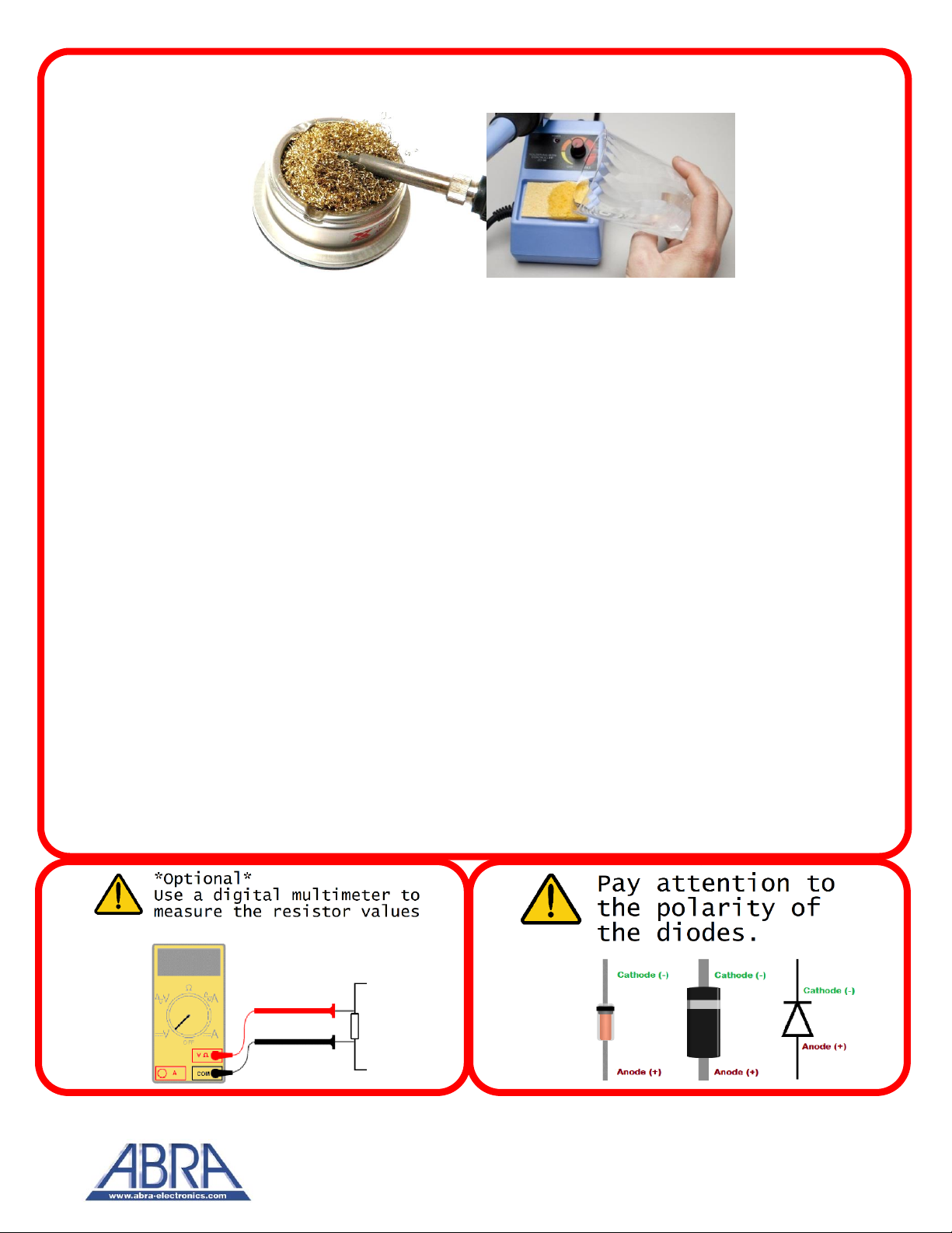
b) The soldering iron temperature depends on the type of solder used.
If you are using a typical 60/40 lead solder, depending on the thickness
the temperature should be set anywhere between 370 to 500 °F (187 to
260 °C). If you are using a lead-free solder, increase above temperatures
by 40 to 70 °F (5 to 20 °C).
*ATTENTION* HIGHER TEMPERATURES WILL DAMAGE THE COMPONENTS ALONG
WITH THE CIRCUIT BOARD.
*ATTENTION*DO NOT TOUCH THE SOLDERING IRON WHEN IT IS HOT.
c) It is recommended that you clean the board with a fine brush, isopropyl
alcohol and lint-free cloth to get rid of any pre-existing residue, glue or dirt.
This way the solder will create a better joint with the copper surface.
d) Have your flush cutter, needle nose plier or tweezers handy.
e) Having a roll of paper tape helps you to keep the components in place
when soldering on the bottom side of the board.
f) Have a rosin flux pen or paste handy. Adding flux to the pads before
soldering the components makes the wetting process easier by letting the
melted solder to flow better on the pad and create a better joint.
*ATTENTION* SOLDERING SHOULD BE DONE IN A VENTILATED AREA. BREATHING SOLDER
FUMES WILL HARM YOU.
g) Always cut the excess leads with a flush cutter once a component is
soldered on the PCB. At least 1mm of the lead should stick out from the
solder joints.

6
To begin the assembly process,
insert the LM393 as shown in the
photo.
Ensure the notch of the Integrated
Circuit aligns with the markings on
the board, also known as the
silkscreen.
All soldering will be done on the
backside of the board.
You may proceed to solder the resistors in
place by following the numbering on the
board and placing the correct color resistor
indicated in the “Bill of Materials” section
on page 3.
It is recommended to solder and cut of the
excess lead with a flush cutter, one resistor
at a time.

7
Insert the transistor as shown in the
picture. Ensure the transistor matches
the outline of the silkscreen.
Please pay attention to the IC number
of the transistors as they both have
different functions and must go in the
correct place for this circuit to work!
Insert the 3mm LED as shown in the
image. Ensure that the orientation of
the LED is correct.
You can either check for the large
plate inside the LED for the cathode,
the body for the side that is cut or the
shortest lead. The cathode must be
inserted into the shaded part.
Save the excess leads from the LED that you have cut-off.
You may also solder the ceramic capacitors label 104, indicated in the orange
box.

8
You may proceed to solder the blue
potentiometer, then proceed to solder
the black buzzer and the four-pin
header.
For the MQ5 element, it is
recommended to solder the element
with the label facing inwards towards
the resistors.
On the provided daughter card, solder the
remaining resistor in the kit with the color band
sequence: Red, Red, Yellow Gold on the two
through-hole pads as shown.

9
This secondary PCB is designed with the audio
chip integrated. You have two options to solder
this component.
Option 1: As shown in the photo, solder the
daughter board on the backside of the board. To
install in the correct orientation, use the MQ5
solder point for reference.
Option 2: As shown in the photo,
solder the daughter board on the
front side using the leads you
placed aside from the LEDs. You
will require a vice to help keep the
components in place.
Implementation:
You have three methods you can use this module. The first method is to use
this device as a standalone module where, when gas is detected in the MQ5
the buzzer will make a noise and D1 will light up to inform you that LPG or NG
has been detected. You may use the potentiometer R3 to adjust the sensitivity
of the detector. We used a firelighter to test this device.
Note: Do not expose the sensor to open flame!

10
The second method to use this module is to connect the third pin to Arduino
analog pin and use analog read sketch to read the values from this module.
This example code can be found in the Arduino IDE under
File>Examples>Basics>AnalogReadSerial.
The third method to use this module is to connect the fourth pin to Arduino
digital pin and use digital read sketch to read when the sensor is active high or
active low.
This example code can be found in the Arduino IDE under
File>Examples>Basics>DigitalReadSerial.

11
Related D.I.Y Kits:
AK-30 D.I.Y MINI Speaker Educational Kit
Acrylic Frame that requires assembly and a controller
board that requires some soldering work to get up and
running.
The provided audio boards come with LED Vu Meter to
see the sound level.
PI-ZEROWH-KIT Raspberry Pi Zero W
Basic Kit
A low-cost method of getting into Linux
environment and providing some pinouts to
interface with some sensors.
Excellent to learn programming using
scratch, OpenCV projects using python script
language or running a 3D printer server using
Octo-print.
EK-1 Theremin Player Kit
A soldering based kit that works as a Theremin when
completed. The sounds coming out of the speaker will
vary depending on the closeness of the fingers to the
photocell sensor.
- Check out more awesome projects at www.abra-electronics.com -

12
Table of contents
Popular Gas Detector manuals by other brands

Regal
Regal 3000 Series Instruction bulletin

AGS
AGS Nitrogen Dioxide Installation operation & maintenance

Honeywell Home
Honeywell Home SiXCOMBO-CN Installation and setup guide

Simtronics
Simtronics GD1 MK3 operating manual

CHANCE
CHANCE C4030979 operating instructions

heimgard
heimgard Combustible Gas Detector quick start guide