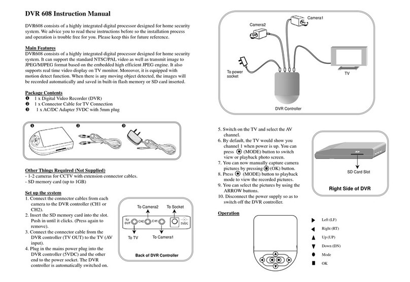
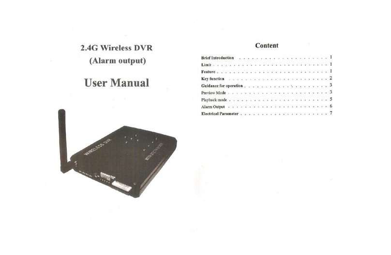
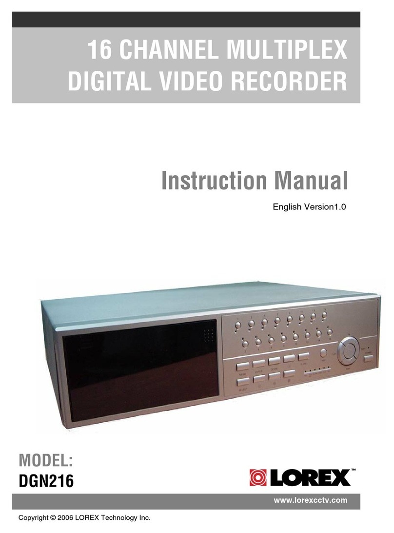
Electronics123 DVR603-12 User manual

DVR603-12
Digital Video Recorder
With Built-in CMOS camera
Introduction
This is a low cost but high performance DVR. By using an advance video DSP, it is able to capture a high
quality image or video clip. The motion detect algorithm is implemented in the design.
Key Features
9Real time Video output to TV
9High Quality JPEG image of mega pixel
9High Quality AVI of VGA at 30fps
9Motion detect of various zone, from 1 to 25 zone
9RTC, OSD
9Date time stamp
9Storage to SD card
9Remote control key operation
9Reserve UART interface for embedding the module to other system
912V DC operation
9Suitable for Gun type or Dome camera case
Block Diagram
Video
Audio
Rev 070625 6
Sensor Board with lens 12VDC
DVR603
Main b
Power Board
oard
Flexible Cable
Mic
USB
IR Rx
Module
SD Card
Alarm
Out
TRG In
Key Board
Keyboard Design
Menu
O
K
RT
PWR On
Mode
LF
DN
UP
We have provided the keyboard for the sample unit such that the customer can evaluate the function of
DVR603 as well as the reference design of the key operation. It is 7- Key design:
mode/menu/UP/DN/LF/RT/OK. Extra key of PWR on is a spare key.
1. Mode: use to change playback or preview
GND
PWR on
Key
2. Menu: for setup or quit the setup
3. LF/RT/UP/DN for item set
4. OK to confirm
5. PWR on – to turn on off the module
Short Cut Key
UP – to turn on off motion detect
DN – to toggle between JPG orAVI
LF – to toggle Trigger input on off
RT – to toggle Alarm output on off

Electrical SpecificationElectrical Specification
VDD = 12VDC TA = 0 to 25oC
Parameter Condition Min Typ Max Unit
DC supply voltage 8 12 13.5 V
Operation Current (w/o SD card) Preview 130 mA
Capture
160 mA
Playback 110 mA
Operation Current ( with 1G SD card) Preview 148 mA
Capture
195 mA
Playback 146 mA
Note: different branded SD card and memory size will have different current consumption.
Power On and settings
Power On Main
Record Setting
Security Setting
System Setup
Exit
1. Note: 12VDC is used in this system, it is converted to 5V and 3.3V for
the DSP and other devices.
2. Plug in power cable and video cable to TV set
3. Press power on button switch once to turn on the module
4. there is power on welcome logo on TV screen
5. the LED on the main board lit up, that means the module is successfully
function.
6. when first time power up, it will enter preview mode, wait a while until the
sensor calibration itself and get the correct white balance and gain, fine
the lens focus is possible
Main Menu
1. Press Menu Key to enter
2. Recording Setting: to Set recording mode, schedule, image quality, auto recording
3. Security Setting, include motion detect setting and alarm output
4. System Setup, to setup date time, language, factory default setting, format SD card
5. use UP/DN to select and OK to enter selection
Recording Menu Recording
JPEG / AVI
Schedule
Image Quality
Exit
1. Format: JPEG or AVI, use LF/RT key to select, OK to confirm, default is
JPEG
2. Schedule: press OK to select, can set daily recording or preset
2.1 if daily, set start time and duration, then the DVR will start recording
everyday at that preset time and duration, duration from 10s, 30s to
1Min.
2.1.1 Time setting: Use LF/RT to select HH, MM, SS, UP/DN key
to change digit.
2.1.2 Duration setting: use UP/DN key to select
Rev 070625 6
Schedule
Daily
Preset interval
Exit
Daily Recording
Start time
00:00:00
Duration
10/30/60s ON/OFF
Exit
2.1.3 Turn on-off the daily recording: use UP/DN to select
Preset Recording
Interval
00:00:00
Duration
10/30/60s ON/OFF
Exit

2.2 If preset recording, then the DVR will perform repeat recording at preset interval and duration. For
instance, if interval is set to 01:00:00(1hr) and duration is set to 10sec, then the DVR will start
recording every one hour for 10sec. Preset interval can be any from 00:00:00 to 23:59:59, duration
from 10s, 30s, to 1Min Image Quality
JPG SXGA/VGA
AVI 10/15/30fps
Exit
2.2.1 Interval setting: Use LF/RT to select HH, MM, SS, UP/DN
key to change digit.
2.2.2 Duration setting: use UP/DN key to select
2.2.3 Turn on-off the interval recording: use UP/DN to select
2.3 User can select either one schedule. If it has been set to Motion
Detect On in security setting, this schedule is therefore turn off
3. Image Quality:
3.1 If set JPEG, can set mega-pixel or VGA, Default mega-pixel, press
LF/RT to toggle, UP/DN to save and leave to other item
3.2 If set AVI, can set frame rate 10fps, 15fps, 30fps, default 10pfs. Use
LF/RT key to toggle
Security Setting
1 Trigger input on/off: to turn on off the trigger input, use LF/RT to select,
UP/DN to confirm and leave Security Setting
Trigger In On/OFF
Alarm Out On/ OFF
Motion Detect ON/OFF
Motion Detect Set
Exit
2 Alarm output on/off: to turn on off the alarm output, use LF/RT to select,
UP/DN to confirm and leave
3 Motion Detect in/off, to turn on off the motion detect function, LF/RT to
select, UP/DN to confirm and leave
4 Motion Detect setup: to set the motion detect items such as the area,
sensitivity and capture properties
Rev 070625 6
Motion Detect
Area Set
Sensitivity
Capture Property
Exit
4.1 Area setting, the whole area is divided to 5x5 grids, user can
select whole or any of 25 grids. By default it is selected the whole
area, use OK to confirm un-select that grid, use LF/RT/UP/DN
key to move other grid, press mode or menu key to save and quit.
Agreen rectangle will be displayed to indicate that the area is not
active.
Sensitivity set up Capture Property
JPG / AVI
SXGA / VGA
10fps 15fps 30fps
10s 30s 60s
Exit
5 Sensitivity Set up
There is a red bar on the left hand side of screen, use UP/DN key to select sensitivity. The higher the dial,
the higher sensitivity.

System Setup
1. Date Time: the system has built-in the real time clock, and time stamping to the image, enter the correct
date time is essential for the system. Press OK to enter date time setting. Use UP/DN to
increase/decrease digit, LF/RT to shift next field, OK to confirm
2. Factory Default setting, In some cases, the user wants to cancel all settings and resume to the factory
setting, press OK to confirm.
System Setup
Date time
Factory Default
Format
Exit
Rev 070625 6
Date Time
YY MM DD
06 01 01
HH MM SS
12 : 00 : 00
Exit
3. Format on board memory or SD card. Reconfirmation is required when press OK
Format
Cancel
Confirm
Operation
Preview:
1. Press mode to toggle between preview or playback
2. At preview mode, use short cut key UP to set MD on off, use DN to set JPG or AVI,
3. Snap shot manually: press OK to take a picture or AVI
Playback
1. at playback mode, use LF/RT to search previous or next file to view, press DN to start playing AVI
2. at playing AVI, use RT for fast forward, press OK to stop, LF for fast backward, OK to stop. Use DN to
pause, UP to resume. During FF or FB, need to stop before change mode. Resume will enter normal play
back speed at any cases.
3. delete file: press Menu to select delete one or delete all, confirmation is required.
Keys Operation matrix
Preview Playback Playing AVI
Mode Change to playback Change to preview -
Menu Enter setup Menu Enter file delete menu
UP MD on off - Resume to normal playing
DN JPG/AVI Enter to play AVI Pause
LF Trigger i/p on Previous file Fast Backward
RT Alarm o/p on Next file Fast Forward
OK Snap shot - Stop
Set up Menu Date time setting
Mode - -
Menu Quit menu mode Quit menu mode
UP Select item Increase digit
DN Select item Decrease digit
LF Cfm and shift to previous Cfm and shift to previous
RT Confirm and shift to next Cfm and shift to next
OK Confirm and quit Cfm and quit
Explanation of the Icons on screen display
Capture mode: AVI Capture mode: JPG
Motion Detect On Alarm Output On
Schedule : Daily Schedule : Interval
Trigger Input On

Application Note
1. Power, video out and Key board Interface
A power board has been added to the main board to allow 12V DC input. 2 connectors are provided for
connecting the video and key board connection. A demo key board has been provided for testing purpose.
Customer can build his own key board for real production.
1.1 Location of the Connector
Rev 070625 6
RCA
1
2
Video_Out
PWRON
SW1
34
MGND
1.2 Key Board Circuit
S106
KEY
T1
12
Right
S101
KEY
T1
12
Menu
R105
6K8 1%
R0603
0.22V
KEY
2.60V
R102
82K 1%
R0603
Down
S105
KEY
T1
12
S104
KEY
T1
12
S102
KEY
T1
12
0.56V
MODE
2.27V
GND
Enter
1.45V
R108
47K 1%
R0603
Up
1.89V
R101
0R
R0603
R103
2K4 1%
R0603
R106
15K 1%
R0603
S103
KEY
T1
12
C101
0.1UF
C0603
S107
KEY
T1
12
R104
150K 1%
R0603
R107
27K 1%
R0603
Left
1.01V
Note: the keyboard input of DSP is connected to internal ADC circuit, thus, the accuracy of the resistor is
important in this application
1.3 Power On switch
1.4 Video Out connector
GND
PWR on
Key
SD Card Sensor Interface
Pwr SW
Vin
GND
Video out
Power Bd

2. Alarm Output and Trigger Input
2.1 Location of the I/O port
J4
R71
10K
R0603
XGPIO 0
J4
J5-2.0
1
2
3
4
5
ADC1
NC
CD3V3
DGND
NC
GND
ADC1
XGPIO0
3.3V
2.2 Alarm Output
The module use XGPIO0 as alarm output, active low. That means, when there is a motion detect
from the image sensor, it will output a low signal. Normally this pin is high, 3.3V
2.3 Trigger Input
The module use ADC1 as trigger input, active low. That means, the module can accept external
trigger signal to do the capture function. It is internal pull high (3.3V).
3. IR Remote control
If user wants to use IR remote control circuit, need to contact the supplier for the version which support IR
remote control.
Rev 070625 6
Table of contents
Other Electronics123 DVR manuals
