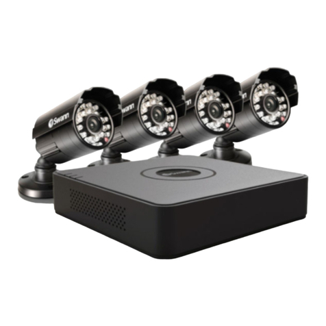
Electronics123 DVR6828 User manual

DVR6828
Video Recording Module
[For Vehicle Application]
Description
This digital video recorder is specially designed for vehicle surveillance. It overcomes machine hang
and files corruption issues, with built-in battery back up and watchdog timer. It is suitable for using in
worst working condition.
Features
9Analog video input
9On board SD card support up to 4GB
9DC12V operation
9Motion detect to capture AVI
9File format – MJPEG
9Video format of 320x240
9Video clip length upto 60sec at 5fps
9Video playback both module and PC
9Pause and resume feature during
playback
9Vehicle number and date time stamp
9Vehicle number and system setup by PC
9Power failure protection to prevent file
corrupt
9Watch dog for system monitoring
9Video output to TV
9On board hardware setting for PAL/
NTSC TV system
9Hot plug key board for system testing and
operation
9Battery backup for 15sec if power failure
Block Diagram
Electrical Characteristics (at room temperature 25C)
Parameter Condition Min Type Max Unit
Operation Voltage 7.5 12 13.5 V
(no power output to camera,
no charging) 180 mA
Operation Current
Recording 190 mA
Power failure time allowed Battery full charged 30 sec
Video Input A/D
Converter SDRAM SD Card
Connector
Compression Engine
Power
DC/DC to
3.3V
Keyboard
buffer UART NOR flash
(firmware)
TV
Monitor
SD Card
4G
Keyboard
PC
Power
12VDC
RTC MCU
BATT
Backup
Release 1.0 20090320 1

Image and file storage information
Image format Video: MJPEG, QVGA (320x240), 1fps
File size per video clip(40sec) ~470KB
Max file number per folder 1024 files
Max folder number per card 1024 folders
Max memory size for SD card 4GB (~8900 clips or 99Hr recording time)
Connector Description
Connector Function Remark
JP1 Select NTSC/PAL Need to be selected before power up
J1 UART To connect PC thru RS232 adapter cable
J2 SD card slot Support up to 4G SD card (note some brands may not
be supported)
J3 Keyboard input 4 bit binary input
J4 Video out To output video signal to TV set
J5 NC
J6 Camera input For video input and power supply
J7 NC
J8 DC input 2-pins, for DC12V input
J9 NC
J10 NC
J11 PWR on-off Slide switch to turn on-off the power and also the
backup battery
Key Definition
Key Name Key Name
0001 SNAP 0111 NOP
0010 OK 1000 NOP
0011 Down 1001 Left
0100 NOP 1010 UP
0101 Right 1011 Mode
0110 DISP 1100 NOP
Note: all other combinations are NOP (no operation)
Release 1.0 20090320 2

System Configuration
1. The system is installed in vehicle, no monitor nor keyboard to be connected when system is
running. For system setup such as, testing, camera position in the vehicle, an external keyboard
and monitor are required.
2. The system accepts clean 12VDC and provides the same 12VDC to supply the external camera as
an option. User needs to provide a regulated 12VDC to this system for the best performance.
3. A Lithium battery is used to backup the system about 15 second to prevent from the file corrupt due
to unexpected power drop. If video recording is taken place this period, it will close file correctly
before turn off the power.
4. A micro controller (MCU) is use to monitor the power and main DSP status to prevent from system
hang. If the system hanged due to any reason, the MCU will re-boot the system until it is operating
normally. If the system cannot be rebooted the first time, it will repeat until it is succeeded.
5. The UART interface is implemented for PC connection.APC application software will be provided
to setup the system and enter the vehicle number.
6. RTC is used for date time display and stamp to the video. The date time can be set by the PC
interface, thru UART port. This makes the operation simpler.
7. File format of video clip is MJPEG. It can be playback on the module or PC. The video clip can be
played in 4 mode, forward, backward, pause, resume playing and stop. In PC, a viewing software is
required since the file format is proprietary.
8. No user menu for the module operation. No file delete is allowed.
Board layout and connector location
J6
Video In & DC out
J4
Video Out
Backup Battery
PAL/NTSC select
SD Card Slot J3
Keyboard
J1
UART
ON-OFF
Switch
J8
12VDC In
Operating the Module
1 Power up system the first time: before power up, connect the device as below:
1.1 J3: to keyboard thru a 5 pin flat cable
1.2 J4: video output to TV set using coaxial cable
1.3 J6: video input, connect to camera output; 12VDC output for camera, if required
1.4 J8: connect the power cable, accept only 12VDC+/-1V, note polarity.
1.5 Insert the SD card. There is no flash memory on board, if there is no SD card, it will not
perform recording. This system supports up to 4G card.
1.6 Slide the on-off switch to ON, now the system will start operation. The welcome logo will
display on the TV screen. Note the power up time may be differed from size of memory
card.
All the connectors have the polarity, need to take care before plug in.
2 Preview Mode:
2.1 Use UP key to turn motion detect (MD) on-off, by default MD is ON.
2.2 Press SNAP key to take a video clip instead of MD function. During recording, a red dot will
be appeared and flashing on top of the screen. It can’t be stopped unless it reaches the
Release 1.0 20090320 3

preset recording time.
2.3 Press MODE to switch between preview or playback mode
3 Playback Mode:
3.1 Press MODE to enter playback mode. It will show the last video captured with the OSD.
This OSD can be removed by pressing UP key. If there is no files inside the memory, it will
pop up “ NO FILE” and return to preview mode
3.2 Use LF/RT key to select the desired video clip.
3.3 Press DN key to start playing the selected video clip
3.4 During playback, use UP to pause, press again or RTkey to resume playing. Use LF/RT key
to play the clip reverse or forward. Use OK key to stop the video and back the start position.
3.5 Press DISP key will enter folder list. Use UP/DN key to select the folder. The folder name is
sorted by the date and time. Press OK to confirm selection.
Note: never pull out the SD Card when the module is recording, the file will be corrupted if do so.
System Setup using PC interface
Before setup, need to prepare the RS232 adapter cable and connect to pc com port. Open the program
DVR6828PC.exe. The application will be opened, as below:
1 Open the COM port: make sure the adapter cable is
connected to the module (J1) and the module is
powered. Select the COM port no. Please note some
PC/notebook uses different number of serial port, need
to check the right port number before it can connected
properly. The baud rate is set to 9600. Press OPEN to
connect to module.
2 Set the Clock: one can get the clock from module or
get the system clock from PC. Then press SET to set
the clock to module. Note that if take the clock from PC
system, need to set ASAP. Since the system clock will
not update this application automatically.
3 Memory Operation: one can format the memory card
by press FORMAT.Awindow will be popped up for
confirmation. Note this action can’t be undo. Once
formatted, the content of the card will be erased.
4 Motion Detect Setting: to turn on-off the MD. By default,
it is always ON at power up. Use short cut key UP to
turn off and ON. Sensitivity can also be selected
5 AVI Setting
5.1 Image quality can be set for Hi, Mid and Lo, the
higher the quality, the bigger the file size.
5.2 Duration: limited to 10-60sec, this is the best
time frame for system, more stable.
5.3 Frame rate: it can be set from 1fps to 5fps, higher frame rate will have bigger file size.
6 Vehicle No.: max 10 characters, include text or digit. This will stamp on the photo at the left hand
side lower bottom.
Note: before connect to PC, please turn off the MD by press UP key, to reduce the error rate.
Key Operation (summary)
Preview Playback During Playing
SNAP Press to capture - -
Mode Enter playback Enter preview -
OK - - Stop
UP MD on/off Turn ON/OFF OSD Pause/Resume
DN - Start playback -
LF - Select file -Resume, reverse
RT - Select file -Resume, forward
DISP - Select folder
Release 1.0 20090320 4
Other Electronics123 DVR manuals
