Modulus M1 Operating and safety instructions
USER SET-UP & INSTALLATION
GUIDE
Fall 2018
QUESTIONS? NEED HELP?
Ou Custome Se vice team is available to you 24 hou s day, 7 days a week.
Call us at 512-953-9600 o email us at supp rt@getm dulus.c m
Copyright 2018, MODULUS MEDIA SYSTEMS INC.
Ge ing S ar ed
Welc me t the w rld f M dulus — the wo ld’s fi st all-in-one
p emium DVR fo the st eaming age. To achieve the best esults with
you new system, please follow the inst uctions below and ensu e
you check and ve ify all connections, netwo k functionality and
exte nal device configu ation settings to accommodate the
Modulus M1 input and output equi ements.
n UNPACKING YOUR SYSTEM
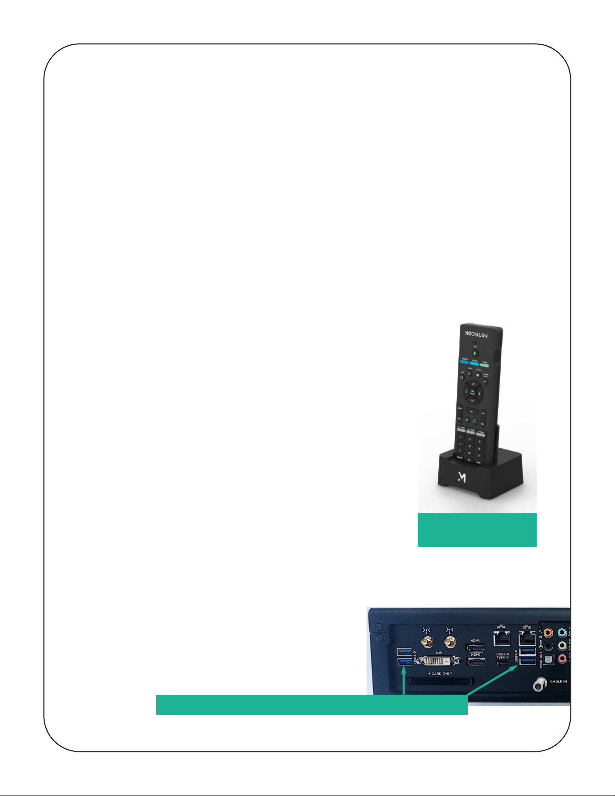
The Modulus M1 unit comes packed with its RC-1 Ultimate
Remote control unit and charging cradle, and USB receiver
Dongle in a separate box on the top of the main unit.
STEP 1: Be sure to remove that box FIRST and place the
M1 remote in its charging cradle (as shown in Fig 1).
The remote is shipped with a minimum charge and will
require at least 30 min charge to function properly. A longer
charging time is better: 4-6 hours is an ideal start, with a full
overnight charge after set-up is complete (for more informa-
tion on the remote see the separate Modulus M1 Remote
Guide Information Sheet).
PLEASE NOTE: The Modulus remote ships in a “power off”
state. Once charged it must be turned on as follows: Hold
the “INFO” key down until the BLUE LED at the top of the
remote control unit illuminates indicating power on.
STEP 2: Plug the included USB Dongle into one
of the rear USB ports on the M1 unit (see Fig. 2).
FIG 1: Remote Control
in charging cradle
FIG 2: Use any of fo r USB ports to connect the Dongle
1
PLEASE NOTE: If the M1 is being rack mounted, an extension cable will need to
be attached to the USB Dongle to ensure it is located outside the metal rack
mount enclosure so it can properly receive the RF signals from the M1 remote.
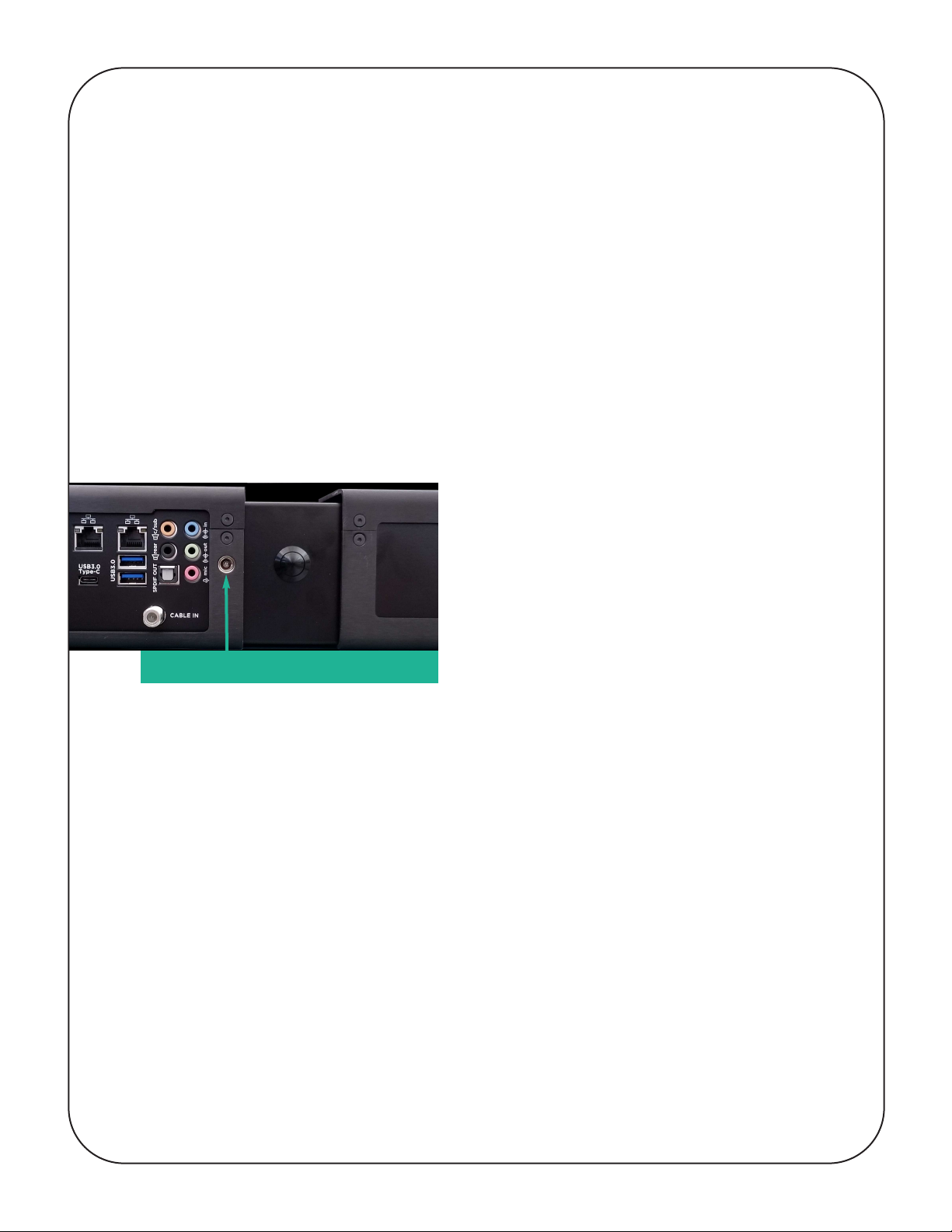
STEP 3: Un-pack and remove the M1 main unit, rack-mount kit (if ordered) and the
power supply from the packaging. DO NOT connect the power supply until all
other connections have been made. Insure that the electrical outlet used for the
power supply is fully grounded and properly wired BEFORE plugging in the M1
supply unit.
The power supply plugs into a small jack on the rear panel shown in Fig 3. Use
only an M1 Modulus supply; general power supplies may not work and could
damage the unit and invalidate the warranty.
STEP 4: If applicable, install the M1 to the Modulus Rack Mount using only the
provided screws found in a small plastic bag with rack mount unit. If no rack mount
is being used, proceed to install the four supplied rubber feet to the bottom of unit
with the provided screws. [This will require a small Allen wrench.]
STEP 5: Locate and position the M1 unit as close to its final actual use location as
feasible before attaching any other connections to ensure all cable have sufficient
length and can be properly connected.
After physical placement / installation, you will need to verify that all additional
connection cables are of sufficient length to allow proper mounting and
installation. These include:
o All HDMI connection cables
o All Over The Air (OTA) Antenna and Cable TV Connections
o All USB Cables
o All Data/Network (RJ45/Cat 5/6) Ethernet Cables
o All other Audio & Video Signal Cables specific to your installation
FIG 3: Connect power s pply here
2
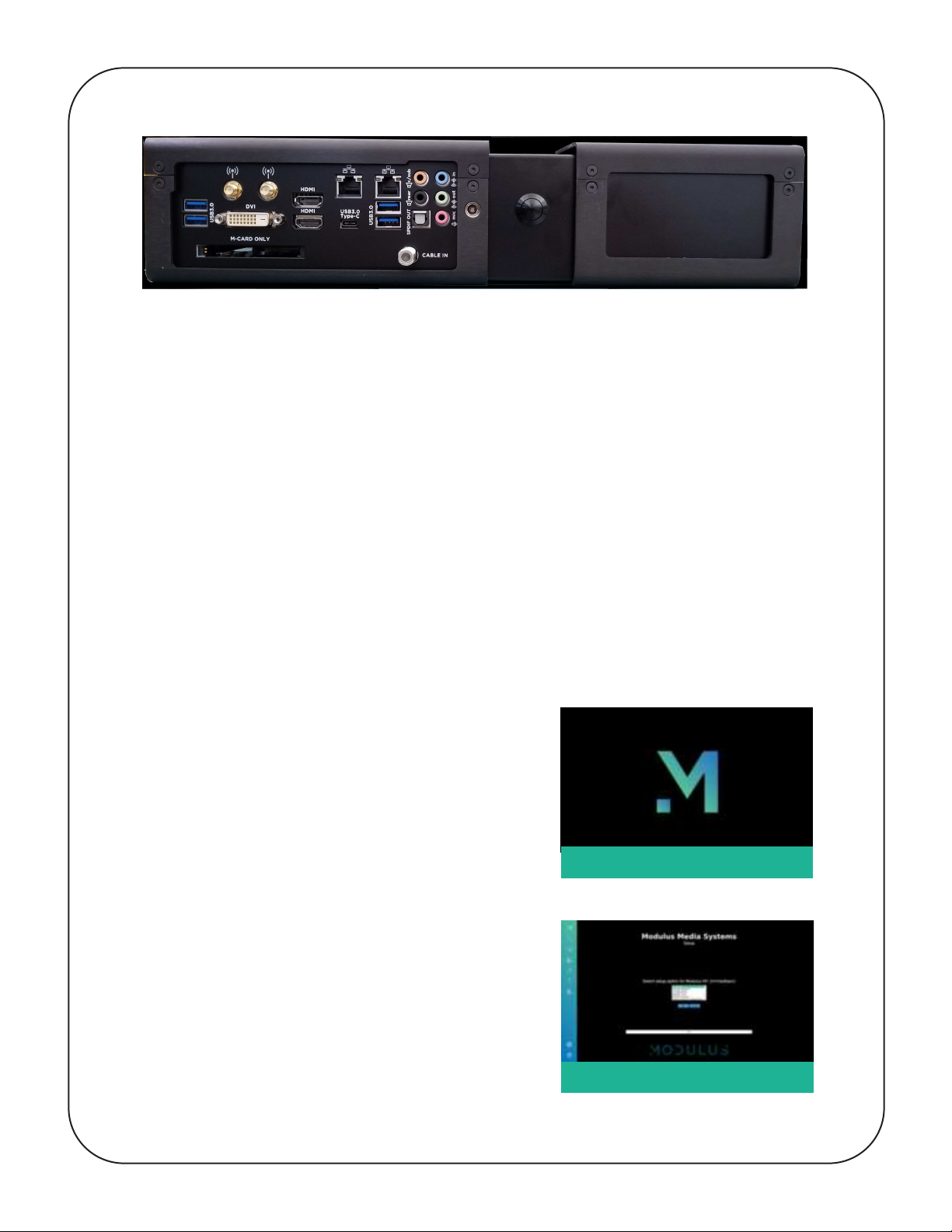
A multitude of connection points
The M1 rear panel (above) shows all feasible connections that can/could be made
to the unit. Each install will be different so it is essential that you verify that all the
cables for your installation can properly connect to the M1 where the unit will be
located.
All these steps completed? ou’re ready to power up!
n INSTALL & CONFIGURATION
STEP 1: Connect the power cable to the M1 and plug into the wall outlet.
STEP 2: Power on the M1 by pressing the power button located in the center of
the rear panel.
Within a few seconds, you should see the
startup image (Figure 4) on your display.
[If you do not see the image, verify that all
connected HDMI devices in the chain are
properly connected and setup.]
STEP 3: The M1 will enter a setup wizard
(Figure 5). Using the remote control’s air
mouse and select buttons, select "Full Setup,"
and then follow the on-screen instructions.
This process will include:
o Renaming your M1
o Network Setup
o Audio Setup
o Running a speaker test
o Tuner & Guide Data Setup
FIG 4: Start- p image screen
FIG 5: Set- p Wizard screen
3

STEP 4: The last step of the setup
process is to check for system updates
(Figure 6). Click the “ es” button to
kick off the update process.
STEP 5: The initial setup of your
Modulus Media System is complete
and after the M1 reboots, you
should see the Main Home
screen on your display (Figure 7).
our system is now ready to deliver
a world-class media experience!
FIG 6: Check for System Updates
FIG 7: Mod l s Home Screen
PLEASE NOTE:
Today’s home theaters have an almost infinite array of
configurations; further customization may be needed
for your system’s specific configuration.
4
Table of contents


