ElectroSteam LG-10 series User manual
www.electrosteam.com
rev. 12222009
User Manual
& Installation Instructions
LG (Cleaner) (Portable)
IMPORTANT –READ ALL INSTRUCTIONS BEFORE OPERATING
All steam boilers are built in accordance with ASME miniature boiler code.
NOTE: It is the responsibility of the installer to conform to any state or local codes. If further
inspection, following modification by installer, is required under state or local codes, that is
the responsibility of the local installer.
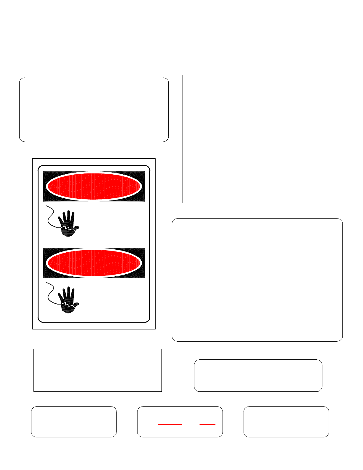
HIGH VOLTAGE
AUTHORIZED
PERSONNEL
ONLY
ALTO VOLTAJE
SOLAMENTE
PERSONAL
AUTORIZADO
DANGER
PELIGRO
CAUTION USE ELECTRICAL
SUPPLY CONDUCTORS RATED
FOR A MINIMUM OF 90°C
AMBIENT TEMPERATURE
AROUND UNIT NOT TO
EXCEED 105° F
TERMINALS ARE SUITABLE
FOR COPPER WIRE ONLY
U.L. 834 PAR. 4416
REPLACE GLASS
EVERY SIX MONTHS RETIGHTEN SIGHT GLASS
BEFORE USE
CAUTION
OH T U
CA OTI N
THROW OFF MAIN
POWER SWITCH
BEFORE WORKING ON
ELECTRICAL CABINET
WARNING - The following labels have been placed on this boiler for YOUR SAFETY. Failure
to observe these instructions could lead to PROPERTY DAMAGE, SEVERE INJURY, or
even DEATH
A MANUAL WAS SHIPPED WITH THIS
BOILER. IT IS IMPORTANT THAT YOU
READ, UNDERSTAND, AND OPERATE
THIS STEAM GENERATOR IN ACCOR-
DANCE WITH THE OPERATING
INSTRUCTIONS CONTAINED IN THE
MANUAL. IF FOR ANY REASON YOU
DO NOT HAVE A MANUAL, CALL
ELECRTO-STEAM AT 800-634-8177

LG-10(C) thru LG-30(C) (Portable) - User Manual Electro-Steam Generator Corp.
3 of 30
TABLE OF CONTENTS
1.)INSTALLATION INSTRUCTIONS ................................................................ 4-7
1.1) STEAM GENERATOR (CLEANER) (PORTABLE) .............................................. 4
1.2)SOLUTION MIXER “OPTIONAL” ..................................................................... 5-7
2.) OPERATION & SEQUENCE OF EVENTS ................................................. 8-9
3.) CLEANING & MAINTENANCE ................................................................. 10-18
3.1) MANUAL “BLOW DOWN” .................................................................................. 10
3.2) CLEANING WATER LEVEL PROBES .......................................................... 10-11
3.3) CLEANING OR REPLACING HEATERS ............................................................ 11
3.4) REPLACING GLASS GAUGE AND RUBBER WASHERS ......................... 12-13
3.4.1) BRASS SIGHT GLASS (STANDARD) ................................................................ 12
3.4.1) BRASS SIGHT GLASS (SEISMIC)..................................................................... 13
3.5) CHAMBER CLEANING & CHEMICAL TREATMENT ............................... 14-15
3.6) PRESSURE CONTROL DATA SHEET ................................................................ 16
3.7) SETTING THE PRESSURE CONTROLS ....................................................... 17-18
4.) CALCULATIONS & DATA SHEETS ........................................................ 19-21
4.1) HEATER POWER & VOLTAGE RATINGS ........................................................ 19
4.2) TOTAL POWER RATING CALCULATIONS ...................................................... 19
4.3) AMPERAGE CALCULATIONS ............................................................................ 20
4.4) ACTUAL POWER RATING CALCULATIONS ...................................................21
4.5) STEAM CAPACITY CALCULATIONS ............................................................... 21
5.) DRAWINGS & WIRING SCHEMATICS ................................................. 22-29
5.1) PARTS LEGENDS ............................................................................................22-24
5.1.1) LG (CLEANER) (PORTABLE) ........................................................................... 22
5.1.2) DELUXE GUN .................................................................................................23
5.1.3) HEAVY DUTY GUN ........................................................................................ 24
5.2) INSTALLATION DATA SHEET ........................................................................... 25
5.3) CONTROL WIRING SCHEMATIC ...................................................................... 26
5.4) HEATER WIRING SCHEMATICS ................................................................. 27-29
5.4.1) LG (10-30KW) (THREE PHASE) ........................................................................ 27
5.4.2) LG (10-30KW) (SINGLE PHASE) ....................................................................... 28
5.4.3) LG (10-30KW) (THREE AND SINGLE PHASE) (550-600V) ...................................29
6.) TERMS & CONDITIONS ..................................................................................... 30

LG-10(C) thru LG-30(C) (Portable) - User Manual Electro-Steam Generator Corp.
4 of 30
1.) INSTALLATION INSTRUCTIONS
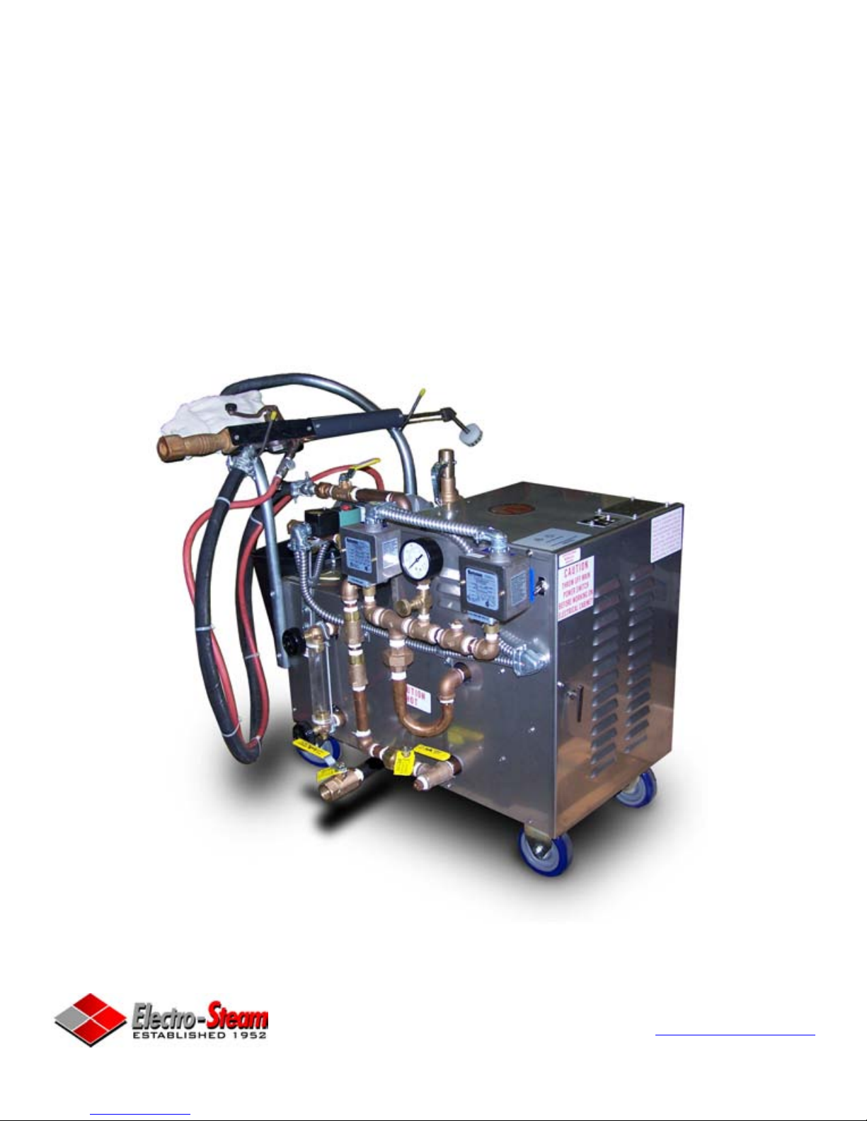
LITTLE GIANT “LG-SERIES” (Cleaner) (Portable)
The Electro-Steam Generator design consists essentially of a high pressure chamber filled with water
that is heated by one or more submerged resistance type electric heating elements. Automatic controls
are provided to maintain the pre-set operating pressure and water level. Safety features include:
automatic low-water cutoff (manual low-water reset optional), dual pressure controls, safety valve, and
visible water level gauge. All of our generators are built in accordance with A.S.M.E. Miniature Boiler
Code and are individually inspected and stamped by an Authorized National Board Insurance Inspector.
IMPORTANT –READ ALL INSTRUCTIONS BEFORE OPERATING
NOTE: For generator measurements, refer to Installation Data Drawing attached. For
interpretation of numbered items, refer to Parts Legend Drawing attached. Ambient
temperature around this unit must not exceed 105°F.
1.1) INSTALLATION INSTRUCTIONS: (CLEANER) (PORTABLE)
Set STEAM GENERATOR on level floor and attach Solution Bucket (#25) into the 2
predrilled holes on the rear of generator, behind the Pump (#8).
CONNECTIONS:
Periodically check all plumbing and electrical connections for tightness; this should also be done
before initial start-up.
ELECTRICAL:
This generator must be connected to a disconnect switch protected by fuses or
a circuit breaker with the proper size wire by a licensed electrician in
accordance with N.E.C. and your local codes –Voltage, KW, and Phase
requirement are marked on the nameplate.
WATER SUPPLY:
Connect city water line to Y-Strainer (#6).
Purity: NOT to exceed 26,000 OHMS per CM
Temperature Range: 32°F – 140°F or 0°C – 60°C.
Pressure Range: 20PSI –150PSI.
*CAUTION: The Pump (#8) requires clean tap water. If the water is not free of foreign matter, a 5
micron cartridge filter should be installed in the water supply line.
STEAM OUTLET:
Connect the 1/4” Union “Female End” (A) on the Steam Hose (I) from the Steam Gun to the
Steam Outlet (1/4” Union “Male End”) (#16).
SAFETY VALVE & DRAIN:
Route Safety Valve (#18)and Manual Drain (#19) separately towards the floor.

a
b
c
d
e
f
5
i
m
k
h
6
r
p
q
n7
g
9
3
2
1
4810 11
12
13
9
s
t
14
15 u
w
v
17
16
x
18
Float & Chain Assembly
5043-A18.
Discharge Tube Assembly
Suction Tube Assembly
5057-A
5058-9A
16.
17.
Nipple, 1/4" x 6"
Elbow, 1/4"
Nipple, 1/4" x Close
Street Elbow, 1/4"
Water Valve Body
Vacuum Breaker
Eductor Assembly
Metering Tip (Kit)
69001515.
9. 505600
519000
505900
506000
506300
440121
13.
14.
10.
12.
11.
5200008.
Valve Parts List6655207.
Screw
Magnet Parts Kit
Nipple, 1/4"
Ball Valve, 1/4"
5030-K6.
4. 360900
10080500
-
5.
5020003.
DESCRIPTION
Strainer Washer
Hose Swivel
KEY PART NO.
506500
238100
2.
1.
a.
Magnet Spring
-f. Magnet
-e. Magnet Cap
-d. Magnet Cover
-c. Washer-b.
j. Lock Washer (Not Shown)
-
Thumb Screw
Screw
-
-k.
m.
U Clamp
Z Bracket
-
-h.
i.
Armature Spring
Diaphram
Armature
Valve Guide ("Bonnet")
-
-
-
-
n.
q.
r.
p.
Suction Stub Only
Eductor Body Only
440100
440101
s.
t.
Ceramic Weight
(Foot Valve & Weight)
Foot Valve, Viton
Tubing, 1/2" x 9'
505809
10076301
250700
250006
v.
w.
-
u.
Bead Chain Only
507200x.
g. -Magnet Yoke
Mounting Bracket Kit (specify model 511)
Hydro Systems Phone: (513) 271-8800
3798 Round Bottom Road Fax: (513) 271-0160
Cincinnati, OH 45244 www.hydrosystemsco.com
LG-10(C) thru LG-30(C) (Portable) - User Manual Electro-SteamGenerator Corp.
1.2) INSTALLATION INSTRUCTIONS - SOLUTION MIXER
HydroMinder Model 511 Parts
Diagram/List "OPTIONAL"
5 of 30

LG-10(C) thru LG-30(C) (Portable) - User Manual Electro-Steam Generator Corp.
6 of 30
1.2) INSTALLATION INSTRUCTIONS –SOLUTION MIXER
“OPTIONAL” (Continued)
NOTE: Refer to “HydroMinder Model 511 Parts Diagram” on previous page for interpretation of
numbered & lettered items. For interpretation of numbered items with “#”, refer to Parts Legend
Drawing attached. For better understanding of installation of Solution Mixer, refer to drawing on
next page.
1. Remove Solution Bucket (#25) from 2 predrilled holes on rear of generator, behind Pump (#8).
2. A red 2’ hose should be enclosed to attach incoming water connection to Solution Mixer. Attach tee
end of hose to Water Inlet (#6).
3. Reattach Solution Bucket (#25) into the 2 predrilled holes on rear of generator, behind Pump (#8).
4. Remove the 2 Screws (6k) holding U-Clamp (6i) and reverse U-Clamp (6i) to where
Thumbscrews (6m) are on outside of Solution Bucket (#25).This allows Solution Mixer to fit
more vertical and Magnet Yoke (5g) moves more freely.
5. Attach Solution Mixer on side of Solution Bucket (#25) opposite the Water Inlet (#6) and Steam
Out (#16). Tighten Thumbscrews (6m).
6. Attach Discharge Tube Assembly (16) to bottom of Eductor Body Only (14s). Push tight on
flange.
7. Remove Metering Tip (15) of your choice from enclosed packet and hand screw into Suction Stub
Only (14t). (Green tip is suggested for initial start up. The solution mixture should be titrated, at end
of gun, or wand, with valve fully open by chemical supplier. Larger or smallerMetering Tips(15)
may be required to achieve proper working concentration.)
NOTE: For better understanding of metering tip selection, refer to section “Metering Tip Selection:”
in the HydroMinder Model 511 Manual enclosed with Solution Mixer.
8. Attach Tubing 1/2” x 9’ (17u) to Suction Stub Only (14t). Push tight on flange.
9. Place Viton Foot Valve (17w) into solution supply.
10. Thread Bead Chain Only (18x) through loop on Magnetic Yoke (5g). Pull Bead Chain (18x) close
so that Float & Chain Assembly (18) is suspended in Solution Bucket (#25). If not suspended,
Solution Bucket (#25) will never fill.
11. Attach other end of red 2’ hose to Hose Swivel (2).
12. Verify that Ball Valve (3) is completely open.
13. Solution Mixer is now ready for use.

LG-10(C) thru LG-30(C) (Portable) - User Manual Electro-SteamGenerator Corp.
1.2) INSTALLATION INSTRUCTIONS - SOLUTION MIXER
"OPTIONAL" (Continued)
7 of 30
2' HOSE USED TO CONNECT WATER INLET OF SOLUTION
MIXER TO INCOMING WATER CONNECTION"
SOLUTION
INLET
METERING TIP
WATER &
SOLUTION
OUTLET
WATER INLET

LG-10(C) thru LG-30(C) (Portable) - User Manual Electro-Steam Generator Corp.
8 of 30
2.) OPERATION & SEQUENCE OF EVENTS
IMPORTANT –READ INSTALLATION INSTRUCTIONS BEFORE OPERATING
START UP:
1. Turn on water supply from the source to the generator.
2. OPEN all valves on generator except for the Manual Drain (#19).
3. Place main disconnect box in ON position and/or plug in.
4. Hold in the Lever Handle (D) on the Steam Gun.
5. Place toggle Switch (#2) in ON position.
•The Water Solenoid (#7) and Pump (#8) will engage and the chamber will begin
to fill with water. As the water level rises, it will make contact with the(G/D) and
(A) probes, indicating the heaters are safely submerged. At this time the
contactor(s) will engage, supplying power to the heaters, causing steam pressure to
accumulate.
•The chamber will continue to fill with water until 1 second after the water makes
contact with the (C) probe, causing the Water Solenoid (#7) and Pump (#8) to turn
off.
•If the contactor(s) still have not engaged at this time, you may need to press the
Safety Reset (#13). If your generator is required to have a Manual Low-Water
Reset (MLWR) (#3), it must be pushed it at this time to engage the contactor(s).
6. Once generator is full of water, release the Lever Handle (D) on the Steam Gun.
•Steam pressure will continue to rise until is reaches 85 PSI. At this time, the
pressure control labeled “Control” will cause the contactor(s) to disengage. The
pressure will drop approximately 5-8 PSI until the “Control” causes the
contactor(s) to reengage, causing the pressure to rise again. The contactor(s) will
continue to cycle on and off during operation.
NOTE: Just because generator is up to pressure does not necessarily mean it is up to
temperature. When first starting generator, before using the gun for operation, you
should use the gun to exhaust pressure, allowing the heaters to remain on longer,
thus increasing the temperature inside the chamber and increasing its ability to
recover from loss of steam.
WARNING – Steam hose and gun will always be hot while generator is on, even when
gun is not is use.
7. The generator is now fully operational and will produce steam until it is turned off.

LG-10(C) thru LG-30(C) (Portable) - User Manual Electro-Steam Generator Corp.
9 of 30
2.) OPERATION & SEQUENCE OF EVENTS (Continued)
•As steam is exhausted, the water level will drop until 3 seconds after it breaks
contact with the (C) probe. At this time, the Water Solenoid (#7) and Pump (#8)
will engage and the chamber will again fill with water. The chamber will continue
filling until 1 second after the water makes contact with the (C) probe. The Water
Solenoid (#7) and Pump (#8) will continue to cycle on and off during operation.
NOTE:If at anytime the “Control” fails and the pressure exceeds 85 PSI, the “Safety”
will cause the contactor(s) to disengage at 90 PSI and will not allow the
contactor(s) to reengage until the Safety Reset (#13) is manually pushed. If this
happens, the “Control” needs to be set lower or must be replaced. If the “Control”
and “Safety” happen to fail, and the pressure reaches 100 PSI, the Safety Valve
(#18) will pop, releasing the pressurized steam. If this happens, all three
components may need to be replaced.
STEAM GUN OPERATION:
NOTE: Refer to Steam Gun Parts Legend for interpretation of lettered items.
1. The special Siphon Steam Gun (Deluxe gun “Standard”, Heavy Duty “Optional”) is
equipped with Steam (I) and Detergent (J) Hoses with valves for steam and detergent
control.
2. The Suction Strainer (B) at the end of the detergent hose should be placed in the
Solution Bucket (#25). Chemicals should be mixed in the bucket in proportions as
recommended by chemical supplier. (Solution Mixer “Optional”)
3. Steam flow is obtained by pressing on the Lever Handle (D) located directly in front of
the handle. A mixture of steam and detergent is obtained by regulating the small
Detergent Valve (H) while operating the Lever Handle (D).
SHUT DOWN:
4. To shut off generator, place Toggle Switch (#2) and Main Disconnect Box in OFF
position and/or unplug the machine. Pressure will drop naturally as the generator cools,
or generator may be drained manually through Manual Drain (#19).(See Manual Blow
Down 3.1)
WARNING – HOT WATER and STEAM under HIGH PRESSURE can lift drain pipes
right off the ground and cause SERIOUS INJURY. Make sure drain pipe is SECURE
and CANNOT move. The drain must be directed into a HIGH TEMPERATURE drain
(NO PVC).

LG-10(C) thru LG-30(C) (Portable) - User Manual Electro-Steam Generator Corp.
10 of 30
3.) CLEANING & MAINTENANCE
The following cleaning procedures are HIGHLY RECOMMENDED in order to keep your
Steam Generator in the best operating condition at all times.
3.1) MANUAL “BLOW DOWN”
A Manual “Blow Down” is an easy way to GREATLY extend the life of your Steam
Generator. The following is the LEAST amount of times recommended to blow down your
generator:
NORMAL WATER AREAS – Should be done ONCE A WEEK.
BAD WATER AREAS – Should be done ONCE A DAY.
NOTE: The best time to Blow Down your generator is after it has been running for some time,
while it is still hot.
1. Place Toggle Switch (#2) and Main Disconnect Box in OFF position and/or unplug the
machine.
2. Allow pressure to drop between 10 and 20 PSI.
3. Open Manual Drain (#19) slowly, allowing HOT WATER and STEAM to blow out
into the drain, cleaning out the generator.
NOTE: Blow Down your generator at any pressure you feel comfortable with. 10 to 20 PSI is
only a recommendation. You may go higher or lower, but higher is always better.
WARNING – HOT WATER and STEAM under HIGH PRESSURE can lift drain pipes right
off the ground and cause SERIOUS INJURY. Make sure drain pipe is SECURE and
CANNOT move. The drain must be directed into a HIGH TEMPERATURE drain (NO
PVC)or outside.
3.2) CLEANING WATER LEVEL PROBES
Water Level Probes are the heart of your generator. Almost all steam generator malfunctions
are caused by dirty water level probes. CLEANING your PROBES is by far the MOST
IMPORTANT maintenance step to keep your generator running properly. The following is the
LEAST amount of times recommended to clean your probes:
NORMAL WATER AREAS – Should be done TWICE A YEAR.
BAD WATER AREAS – Should be done 3-4 TIMES A YEAR.
NOTE: The best time to clean your probes is before you turn your generator on, while it is still
cool.
1. Place Toggle Switch (#2) and Main Disconnect Box in OFF position and/or unplug the
machine.
2. Make sure generator is cool and the Pressure Gauge (#15) reads 0 PSI.
3. Remove cover plate, exposing the Water Level Probes (#5).
4. Use 5/16” Socket to remove wires from probes.
5. Use 13/16” Spark Plug Socket to remove probes from chamber.
LG-10(C) thru LG-30(C) (Portable) - User Manual Electro-Steam Generator Corp.
11 of 30
3.2) CLEANING WATER LEVEL PROBES (Continued)
6. Clean probes to remove rust and scaling.
NOTE: To clean probes you may use wire wheel, wire brush, steal wool, or Scotch-Brite.
(Wire wheel works the best) You may also want to try some sort of chemical like CLR
remover or LIME-A-WAY.
7. Reinstall probes assuring each probe’s length is assigned to its proper letter.
8. Reconnect wires to probes assuring each color is also assigned to its proper letter.
NOTE: DO NOT make wires too tight. Just tighten enough to make contact. Over
tightening can cause probe plugs to pull apart over time.
9. Reinstall cover plate.
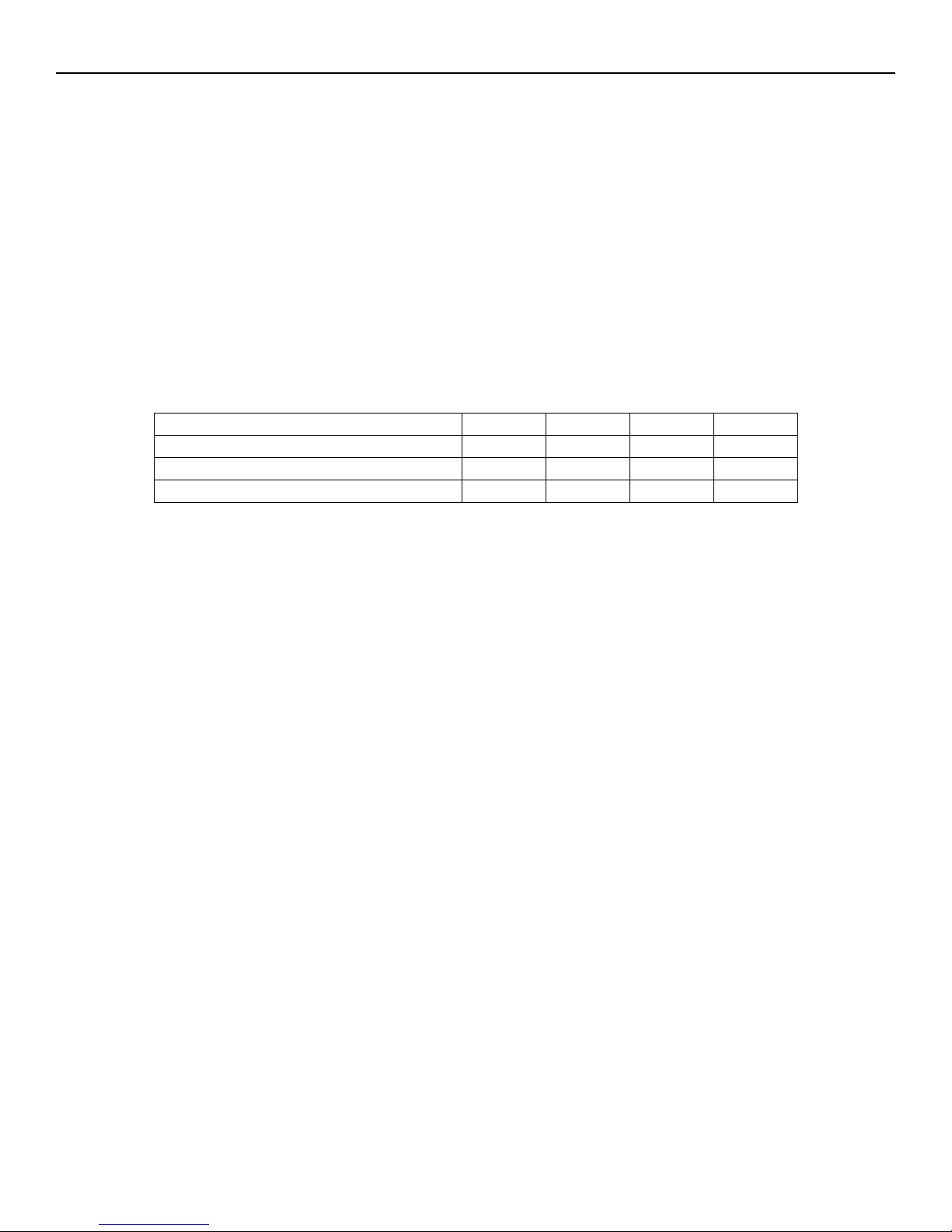
Water Level Probe Specifications:
Letter Assignment on Chamber A B C D/G
Water Level Probe Length 4 ½” 4 ¾” 3 ¾” 4 ¾”
Wire Color Assignment RED Not Used
BLACK
GREEN
Assignment on Dual Function Board LLCO Not Used
H G
NOTE: The (B) Probe is not used. It is a spare probe that can be cut and used to replace any one
of the other probes.
WARNING – There MUST be NO PRESSURE in the chamber when removing probes. If you
must change probes while chamber is HOT, make sure the steam out and drain valves are open
to assure chamber will remain depressurized. DO NOT touch probes with your bare hands
while HOT, and be cautious of escaping steam from probe holes while probes are removed.
3.3) CLEANING OR REPLACING HEATERS
Heaters are located inside the control panel (#1) below the insulation barrier, bolted into the
chamber. If (3.5) Chamber Chemical/Acid Treatments are not regularly done, heaters must be
taken out at least ONCE A YEAR, cleaned with wire brush and reinstalled using a new gasket.
If you are replacing or cleaning your heater elements:
1. Place Toggle Switch (#2) and Main Disconnect Box in OFF position and/or unplug.
2. Make sure generator is cool and the Pressure Gauge (#15) reads 0 PSI.
3. Remove heater wires from heater(s), using an 11/32” or 3/8” Socket.
4. Unbolt and remove heater(s) using a 1/2” Socket.
NOTE: Heater(s) may be difficult to get out; you may need to use some sort of pry bar to
get them loose.
5. Clean heater(s) with wire brush. If replacing, dispose of old heater(s).
6. Reinstall heater(s) with new gasket(s).
7. Attach heater wires assuring proper wiring. *Refer to Heater Wiring Schematics
attached*
NOTE: If you are replacing a heater because of a heater failure, you must also clean the probes
and clean out the chamber, or you may have another heater failure within 48 hours.

LG-10(C) thru LG-30(C) (Portable) - User Manual Electro-Steam Generator Corp.
12 of 30
3.4) REPLACING GLASS GAUGE & RUBBER WASHERS OR
GLASS PACKINGS
The Sight Glass (#10) gives the operator the ability to easily monitor the actual water level
inside the chamber. If the Sight Glass (#10) gets clogged or is no longer functional, it can be very
difficult to troubleshoot a problem.
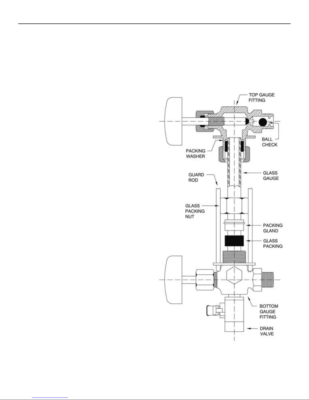
3.4.1) BRASS SIGHT GLASS (STANDARD)
GLASS GAUGE and RUBBER WASHERS
MUST be replaced EVERY SIX MONTHS
INSTALLATION:
Only properly trained personnel should install and
maintain water gauge glass and connections.
Remember to wear safety gloves and glasses
during installation. Before installing, make sure
all parts are free of chips and debris.
1. Uninstall GUARD RODS, GLASS GAUGE, and
RUBBER WASHERS. (You may need to rotate one of the
GAUGE FITTINGS to remove GLASS GAUGE)
2. Slip a new RUBBER WASHER on the new GLASS
GAUGE about an inch from the bottom.
3. Now slip the following items through the top of GLASS
GAUGE in the following order:
• FRICTION WASHER
• GLASS PACKING NUT (facing down)
• GLASS PACKING NUT (facing up)
• FRICTION WASHER
• RUBBER WASHER (inch down from top)
4. Gently insert GLASS GAUGE into GAUGE FITTINGS.
You may need to rotate GAUGE FITTINGS until
vertically aligned, after GLASS GAUGE is in.
5. Carefully raise GLASS GAUGE about 1/16” from bottom
and slide lower RUBBER WASHER down until it makes
contact with the BOTTOM GAUGE FITTING. (DO NOT
allow GLASS GAUGE to remain in contact with any metal)
6. Carefully slide upper RUBBER WASHER up as far as
possible.
7. Hand tighten both GLASS PACKING NUTS, then tighten
1/2 turn more by wrench. Tighten only enough to prevent
leakage. DO NOT OVER TIGHTEN! If any leakage
should occur, tighten slightly, a quarter turn at a time,
checking for leakage after each turn.
8. Reinstall GUARD RODS.
LG-10(C) thru LG-30(C) (Portable) - User Manual Electro-Steam Generator Corp.
13 of 30
3.4) REPLACING GLASS GAUGE & RUBBER WASHERS OR
GLASS PACKINGS (Continued)
The Sight Glass (#10) gives the operator the ability to easily monitor the actual water level inside the
chamber. If the Sight Glass (#10) gets clogged or is no longer functional, it can be very difficult to
troubleshoot a problem.
3.4.2) BRASS SIGHT GLASS (SEISMIC)
GLASS GAUGE and GLASS PACKINGS MUST be
replaced EVERY SIX MONTHS
The Seismic Sight Glass is equipped with BALL
CHECKS in each GAUGE FITTING.
INSTALLATION:
Only properly trained personnel should install and
maintain water gauge glass and connections. Remember
to wear safety gloves and glasses during installation.
Before installing, make sure all parts are free of chips
and debris.
1. Uninstall GUARD RODS, GLASS GAUGE, and GLASS
PACKINGS. (You may need to rotate one of the GAUGE
FITTINGS to remove GLASS GAUGE)
2. Slip a new GLASS PACKINGS on the new GLASS
GAUGE about an inch from the bottom.
3. Now slip the following items through the top of GLASS
GAUGE in the following order:
• PACKING GLAND (facing down)
• GLASS PACKING NUT (facing down)
• GLASS PACKING NUT (facing up)
• PACKING GLAND (facing up)
• GLASS PACKINGS (inch down from top)
• PACKING WASHER
4. Gently insert GLASS GAUGE into GAUGE FITTINGS.
You may need to rotate GAUGE FITTINGS until
vertically aligned, after GLASS GAUGE is in.
5. Carefully raise GLASS GAUGE about 1/16” from bottom
and slide lower GLASS PACKINGS down until it makes
contact with the BOTTOM GAUGE FITTING. (DO NOT
allow GLASS GAUGE to remain in contact with any
metal)
6. Carefully slide upper GLASS PACKINGS up as far as
possible.
7. Hand tighten both GLASS PACKING NUTS, then tighten
1/2 turn more by wrench. Tighten only enough to prevent
leakage. DO NOT OVER TIGHTEN! If any leakage
should occur, tighten slightly, a quarter turn at a time,
checking for leakage after each turn.
8. Reinstall GUARD RODS.

LG-10(C) thru LG-30(C) (Portable) - User Manual Electro-Steam Generator Corp.
14 of 30
3.5) CHAMBER CHEMICAL/ACID TREATMENT
All Electric Steam Generator should be cleaned regularly. The following is the least amount of
times recommended to clean out your chamber:
NORMAL WATER AREAS – Should be done ONCE A YEAR.
BAD WATER AREAS – Should be done TWICE A YEAR.
Chamber Treatment Instructions:
1. Turn on generator, allowing pressure to climb to 10 to 20 PSI on Pressure Gauge (#15),
and then shut off.
2. “Blow Down” Open Manual Drain (#19) slowly, allowing HOT WATER and STEAM
to blow out into the drain.
NOTE: You may Blow Down your generator at any pressure you feel comfortable with. 10
to 20 PSI is only a recommendation. You may go higher or lower, but higher is always
better.
WARNING – HOT WATER and STEAM under HIGH PRESSURE can lift drain pipes
right off the ground and cause SERIOUS INJURY. Make sure drain pipe is SECURE and
CANNOT move. The drain must be directed into a HIGH TEMPERATURE drain (NO
PVC).
3. Remove Safety Valve (#18).
WARNING – There MUST be NO PRESSURE in the chamber when removing the Safety
Valve (#18), make sure the steam out and drain are open to assure chamber will remain
depressurized. Be cautious of escaping steam from chamber while Safety Valve (#18) is
removed.
4. Close Manual Drain (#19) and Steam Out (#16); turn generator on until Sight Glass
(#10) shows that it is 1/2 full, and then shut off.
5. Insert funnel into coupling, where Safety Valve (#18) used to be.
6. Pour a 1/2 Gallon of hydrochloric acid (inhibited) solution (NON-FOOD
APPLICATIONS) into funnel very slowly, being careful of fumes and venting while
pouring.
NOTE: Solution can be obtained from any industrial chemical dealer.
FOR FOOD APPLICATIONS: Use FDA approved chemicals.
7. Remove funnel, reinstall Safety Valve (#18), and verify Steam Out (#16) is closed; let
solution set in generator for 1 HOUR.
8. Turn on generator, allowing pressure to climb to 5 PSI on Pressure Gauge (#15), and then
shut off.

LG-10(C) thru LG-30(C) (Portable) - User Manual Electro-Steam Generator Corp.
15 of 30
3.5) CHAMBER CHEMICAL/ACID TREATMENT (Continued)
9. Allow the pressure to drop to 0 PSI on Pressure Gauge (#15) naturally. DO NOT open
Steam Out (#16) or Manual Drain (#19) until pressure is down.
10. Remove Safety Valve (#18).
11. Reinsert funnel, and fill generator completely to the top with clean water; let stand for an
additional 1/2 HOUR.
NOTE: Turning on the generator will not completely fill it to the top. Filling must be done
manually through the safety valve coupling.
12. Open Manual Drain (#19) to drain generator.
13. Close Manual Drain (#19); refill generator completely to the top with clean water and
open Manual Drain (#19) to flush out generator completely.
14. Reinstall Safety Valve (#18) and close Manual Drain (#19).
15. Turn on generator, allowing pressure to climb to 10 to 20 PSI on Pressure Gauge (#15),
and then shut off.
16. “Blow Down” Open Manual Drain (#19) slowly, allowing HOT WATER and STEAM
to blow out into the drain.
NOTE: You may Blow Down your generator at any pressure you feel comfortable with. 10
to 20 PSI is only a recommendation. You may go higher or lower, but higher is always
better.
WARNING – HOT WATER and STEAM under HIGH PRESSURE can lift drain pipes
right off the ground and cause SERIOUS INJURY. Make sure drain pipe is SECURE and
CANNOT move. The drain must be directed into a HIGH TEMPERATURE drain (NO
PVC).
17. Your generator is now ready for normal use and operation.

LG-10(C) thru LG-30(C) (Portable) - User Manual Electro-Steam Generator Corp.
16 of 30
3.6) PRESSURE CONTROL DATA SHEET
DEFINITIONS:
“CONTROL” PRESSURE CONTROL – This pressure control should be the only one controlling
the operating pressure of the generator.
“SAFETY” PRESSURE CONTROL – This pressure control is only used if the “Control” fails. It
is always set higher than the “Control”; if the operating pressure is passed, The “Safety” will turn
the heaters off.
SAFETY RESET – This reset is tripped when the “Safety” turns the heaters off. It must be
manually pushed to turn the heaters back on. This lets the user know there was a problem. If it is
tripped, the “Control” most likely failed.
PRESSURE ADJUSTING DIAL – These dials adjust the set pressure at which each pressure
control will turn the heaters off.
DIFFERENTIAL ADJUSTING DIAL – This dial is only on the “Control”. When the “Control”
turns the heaters off, the amount of pressure that is dropped before it turns the heaters back on (the
differential) can be adjusted by this dial. This dial should never have to be adjusted, unless desired.
PRESSURE GAUGE – This tells the user what pressure is in the chamber. The pressure controls
are set to this gauge.
LG-10(C) thru LG-30(C) (Portable) - User Manual Electro-Steam Generator Corp.
17 of 30
3.7) SETTING THE PRESSURE CONTROLS
SETTING PRESSURE CONTROLS INSTUCTIONS:
WARNING – The pressure controls must be set while all circuits are live.TO AVOID
ELECTRICAL SHOCK, DO NOT TOUCH the wires or the terminals in which they
connect while setting the pressure controls.
NOTES:
-Setting the pressure controls greatly relies on your ability to tell whether the contactor(s) are
turning the heaters on or off. You should be able to hear the contactor(s), located inside the
Control Box (#1), click on and off. Familiarize yourself with this sound.
-The order in which the pressure controls must be set is the“SAFETY” and then the
“CONTROL”.
-In order to set the “SAFETY” you must keep the “CONTROL” at a higher pressure setting
than the “SAFETY”
-Once the “SAFETY” is set, then you can
lower the “CONTROL” to its correct setting.
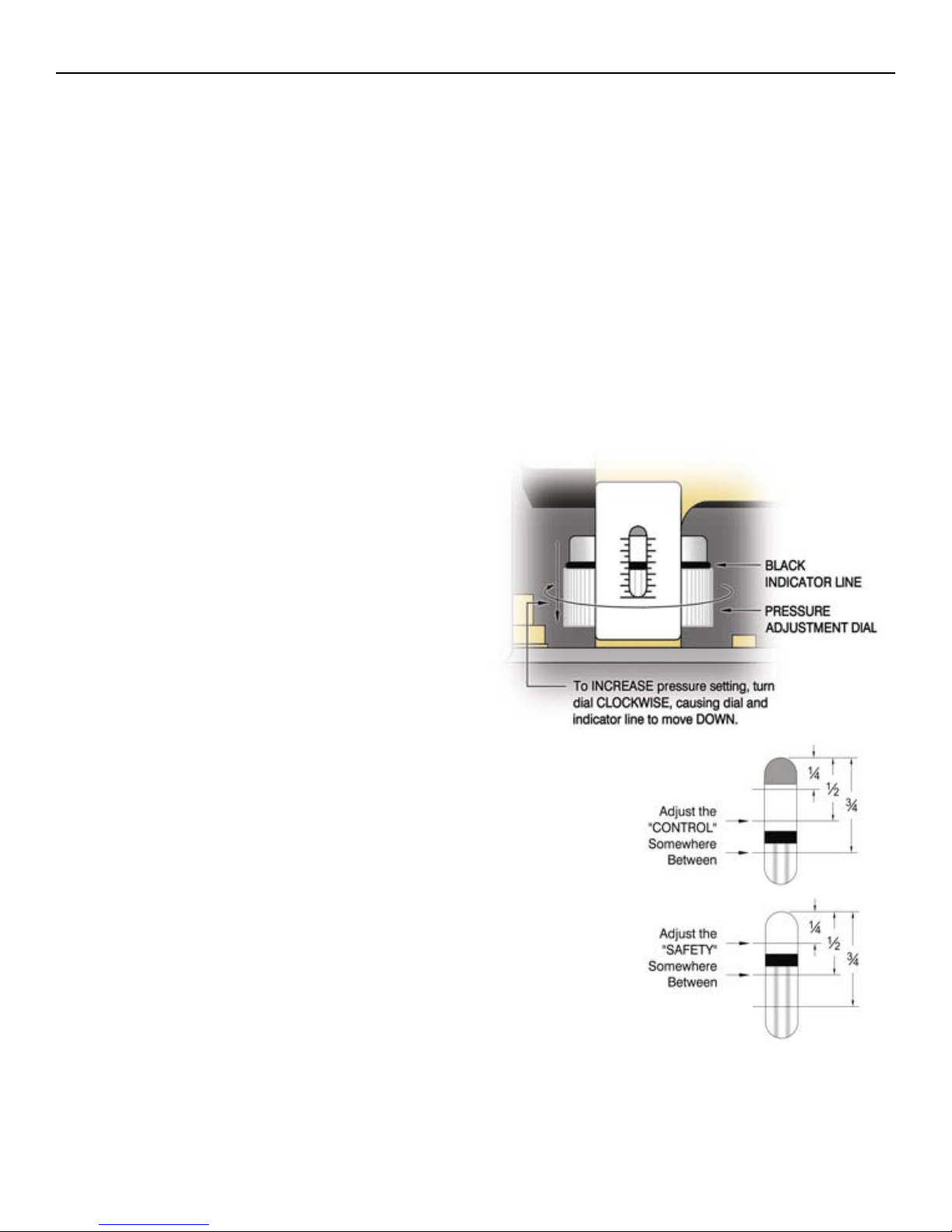
-To INCREASE the pressure setting, when
looking down on pressure control, using your
two index fingers, turn the PRESSURE
ADJUSTMENT DIAL CLOCKWISE,
causing the BLACK INDICATOR LINE to
move DOWN the scale.
-To DECREASE the pressure setting, turn the
dial COUNTER CLOCKWISE, causing the
indicator line to move UP the scale.
SETTING INSTRUCTIONS:
2. Adjust the PRESSURE ADJUSTMENT DIAL on the
“CONTROL” so that the BLACK INDICATOR LINE is
somewhere between ½ and ¾ of the way down from the top.
3. Adjust the PRESSURE ADJUSTMENT DIAL on the
“SAFETY” so that the BLACK INDICATOR LINE is
somewhere between ¼ and ½ of the way down from the top.
4. Close the Steam Out (#16) and turn on generator. When the
contactor(s) click on, the pressure will rise. If contactor(s) do not
click on right away, you may need to press SAFETY RESET.
Continue to watch the Pressure Gauge (#15) until you hear the
contactor(s) click off. This may take up to 20 minutes.
WARNING – DO NOT allow the pressure to reach 100 PSI, the rating on the Safety Valve
(#18). If contactor(s) do not turn off before 95 PSI, manually shut off generator, open the
Steam Out (#16), and DECREASE the pressure setting on the “SAFETY” pressure control.
Repeat step #4.
1. Open the pressure control covers, as shown on previous page.
LG-10(C) thru LG-30(C) (Portable) - User Manual Electro-Steam Generator Corp.
18 of 30
3.7) SETTING THE PRESSURE CONTROLS (Continued)
5. At this point the contactor(s) should be clicked off and you should be able to click them on
and then off again by pressing the SAFETY RESET. This is a way to test if the “SAFETY”
is still controlling the pressure, and not the “CONTROL”. While setting the “SAFETY” and
the contactor(s) are off, if the SAFETY RESET does not cause the contactor(s) to click on
and off again, INCREASE the setting on the “CONTROL”
WARNING – DO NOT allow the pressure to exceed 100 PSI. If contactor(s) do not turn off
before 95 PSI, manually shut off
generator, open the Steam Out (#16), and
DECREASE the pressure setting on the
“SAFETY” pressure control. If you
cannot get the “SAFETY” to control the
pressure, it may need to be replaced.
6. Open the Steam Out (#16) to exhaust some pressure. Continue pressing the SAFETY
RESET until the contactor(s) click on and remain on. The pressure should eventually begin
to rise. If it doesn’t, throttle the Steam Out (#16) somewhere between closed and open until it
does.
7. Pay attention to what the pressure reads when the contactor(s) click off. If the pressure
stopped BELOW 90 PSI,then INCREASE the pressure setting on the “SAFETY”. If the
pressure stopped ABOVE 90 PSI, then DECREASE the pressure setting.
8. Continue to watch the pressure go up and down, while adjusting the “SAFETY” and
pressing the SAFETY RESET,until the pressure stops at 90 PSI.
9. At this point the “SAFETY” should be set at 90 PSI, and the “CONTROL” should be set
somewhere above 90 PSI.
10. Let the pressure drop below 85 PSI and then press the SAFETY RESET, so that the
contactor(s) click on. DECREASE the pressure setting on the “CONTROL” until the
contactor(s) click off.
11. Repeat Step 10 until you no longer need to press the SAFETY RESET for the contactor(s)
to click on.
12. Continue to watch the pressure go up and down, while adjusting the “CONTROL”, until the
pressure stops at 85 PSI.
13. The Pressure Controls are now set.
NOTE: If at anytime the SAFETY RESET needs to be pressed after the pressure controls are
set, either one of the controls are bad, the “SAFETY” is set too low, or the “CONTROL” is
set too high.
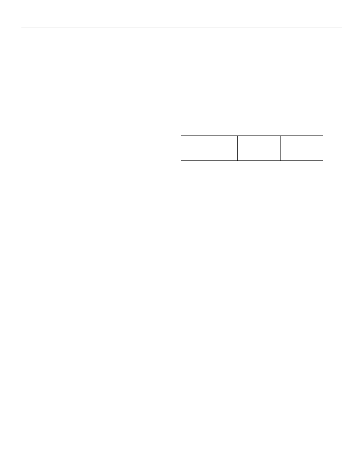
Pressure Control Settings
“Control” “Safety”
Cleaner
(0-100 PSI) 85 PSI 90 PSI
LG-10(C) thru LG-30(C) (Portable) - User Manual Electro-Steam Generator Corp.
19 of 30
4.) CALCULATIONS AND DATA SHEETS
4.1) HEATER POWER & VOLTAGE RATINGS
LG Model units use 3 Heaters to meet the required (KW) POWER from the customer’s
specified INPUT VOLTAGE. Each heater comes in 5different (KW) POWER RATINGS and
4different VOLTAGE RATINGS.
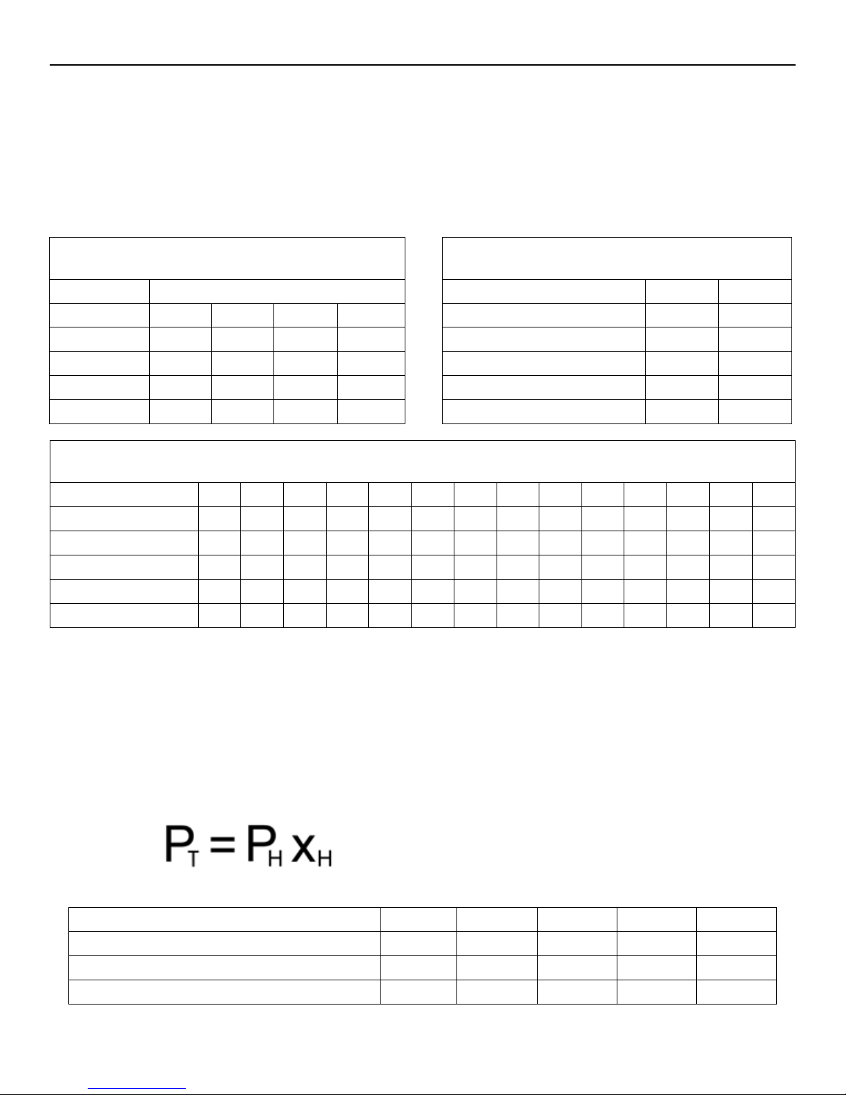
HEATER VOLTAGE RATINGS per INPUT VOLTAGE (VOLTS)
Input Voltage 208 220 230 240 380 400 415 425 440 460 480 550 575 600
LG-10 208 208 240 240 208 240 240 240 480 480 480 600 600 600
LG-15 208 230 230 230 208 230 230 230 480 480 480 600 600 600
LG-20 208 230 230 230 208 230 230 230 480 480 480 600 600 600
LG-25 214 214 240 240 214 214 240 240 480 480 480 600 600 600
LG-30 208 208 240 240 208 240 240 240 480 480 480 600 600 600
NOTE: 380-425V heaters are not usually rated for 380-425V. They are usually 208-240V heaters
that have been re-stamped 380-425V and wired in series.
4.2) TOTAL POWER RATING CALCULATIONS
The HEATER POWER RATING and NUMBER OF HEATERS are used to calculate the
TOTAL POWER RATING.Since the HEATER POWER RATINGS are in Kilowatts, they
must be multiplied by 1000 to convert them to Watts.
DEFINITIONS:
PT= Total Power Rating
PH= Heater Power Rating
xH= Number of Heaters
MODEL UNIT LG-10 LG-15 LG-20 LG-25 LG-30
Heater Power Rating (Watts) 3,333 5,000 6,500 8,333 9,750
X Number of Heaters 3 3 3 3 3
Total Power Rating (Watts) 10,000 15,000 19,500 25,000 29,250
AVAILABLE HEATER RATINGS
KW VOLTAGES
3.33 208 240 480 600
5.00 208 230 480 600
6.50 208 230 480 600
8.33 214 240 480 600
9.75 208 240 480 600
POWER RATINGS per MODEL
MODEL UNIT QUAN. KW
LG-10 3 3.33
LG-15 3 5.00
LG-20 3 6.50
LG-25 3 8.33
LG-30 3 9.75
LG-10(C) thru LG-30(C) (Portable) - User Manual Electro-Steam Generator Corp.
20 of 30
4.3) AMPERAGE CALCULATIONS
The INPUT VOLTAGE, PHASE, TOTAL POWER RATING, and HEATER
VOLTAGE RATING are used to calculate the amperage.
NOTE: 380-425V heaters are not usually rated for 380-425V. They are usually 208-240V heaters
that have been re-stamped 380-425V and wired in series.
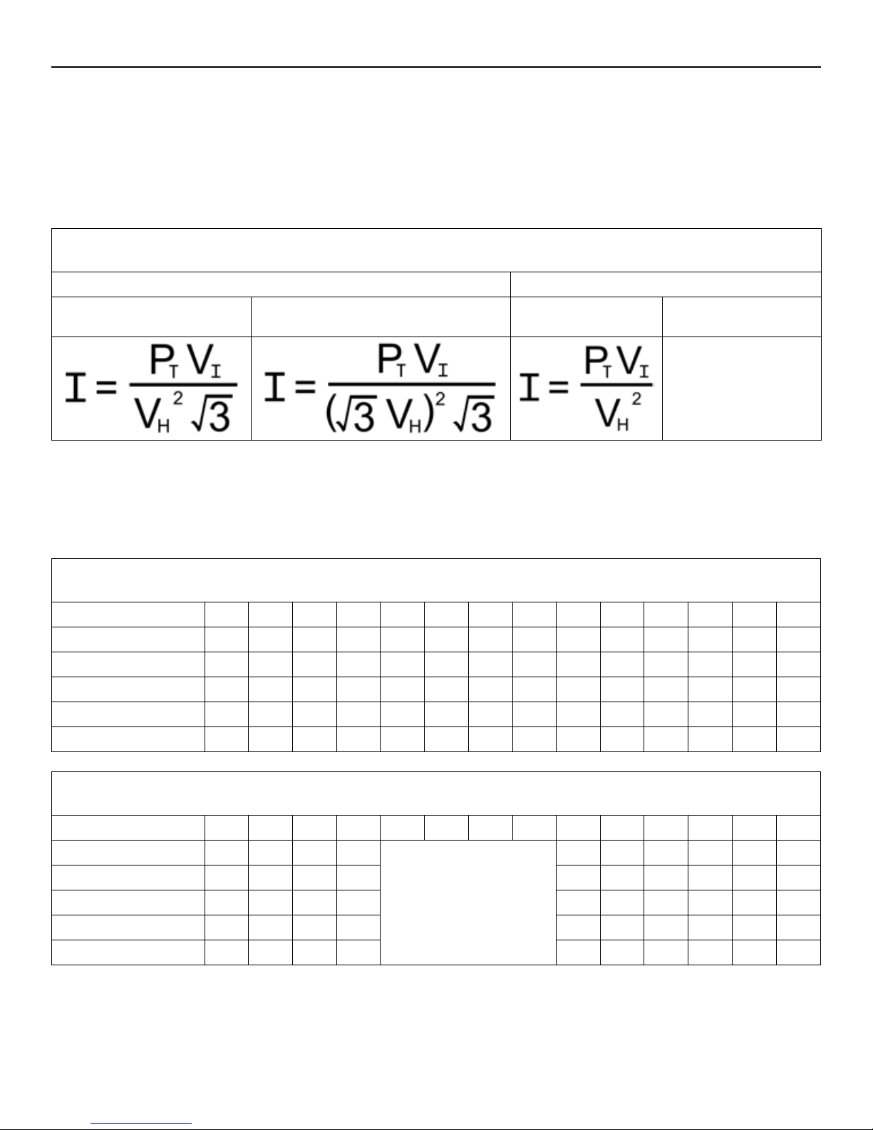
FORMULAS TO CALCULATE AMPERAGE
THREE PHASE SINGLE PHASE
208-240V & 440-600V 380-425V
(using 208-240V heaters) 208-240V &
440-600V 380-425V
(using 208-240V)
Not possible with
odd number of
heaters
DEFINITIONS:
I = Amperage VI= Input Voltage
PT= Total Power Rating VH= Heater Voltage Rating
THREE PHASE AMP DRAW CALCULATIONS (AMPS)
Input Voltage 208 220 230 240 380 400 415 425 440 460 480 550 575 600
LG-10 27.8 29.4 23.1 24.1 16.9 13.4 13.9 14.2 11 11.5 12 8.82 9.22 9.62
LG-15 41.6 36 37.7 39.3 25.4 21.8 22.6 23.2 16.5 17.3 18 13.2 13.8 14.4
LG-20 54.1 46.8 48.9 51.1 33 28.4 29.4 30.1 21.5 22.5 23.5 17.2 18 18.8
LG-25 65.6 69.3 57.6 60.1 39.9 42 34.7 35.5 27.6 28.8 30.1 22.1 23.1 24.1
LG-30 81.2 85.9 67.4 70.4 49.4 39.1 40.6 41.5 32.3 33.7 35.2 25.8 27 28.1
SINGLE PHASE AMP DRAW CALCULATIONS (AMPS)
Input Voltage 208 220 230 240 380 400 415 425 440 460 480 550 575 600
LG-10 48.1 50.9 39.9 41.7 19.1 20 20.8 15.3 16 16.7
LG-15 72.1 62.4 65.2 68.1 28.6 29.9 31.3 22.9 24 25
LG-20 93.8 81.1 84.8 88.5 37.2 38.9 40.6 29.8 31.1 32.5
LG-25 114 120 99.8 104 47.7 49.9 52.1 38.2 39.9 41.7
LG-30 141 149 117 122
Not possible with odd
number of heaters
55.9 58.4 60.9 44.7 46.7 48.8
This manual suits for next models
6
Table of contents
Popular Steam Cleaner manuals by other brands


Cleanmaxx
Cleanmaxx GJ-FC03 operating instructions

Redfern Enterprises
Redfern Enterprises EUROSTEAM DUET instruction manual

POLTI
POLTI VAPORETTO 2085 Usage instructions

DS Produkte
DS Produkte PC-P008E instruction manual

POLTI
POLTI MONDIAL VAP 7000 INOX Instructions for use

Shark
Shark PRO PORTABLE STEAM POCKET SC3901W owner's guide


