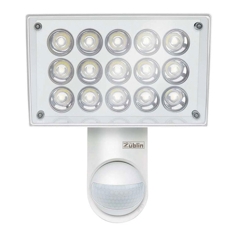
Electrovision NJ174 COTO CIRC User manual

NJ174
OCTO CIRC
360 10mm LEDs in 3 colours
Low power consumption
Stand-alone or DMX operation
Page 1

IMPORTANT
Installer and Users please note:
These instructions should be read carefully and left with
the user of the product for future reference.
BEFORE USE
You must inspect the product including its cable and plug
for any signs of damage. If the product is damaged, DO
NOT use it, and contact your supplier immediately.
INSTALLATION
A risk assessment should be carried out before
commencing work. Fix the luminaire with the hanging
bracket provided. To conform with Health & Safety
legislation, a safety chain will also be required. Attach
the safety chain to the "Safety Eye" on the rear panel.
If permanently installed, the luminaire must be installed
by a competent electrician in accordance with the latest
IEE Wiring Regulations.
Either
plug the lead into a 13 A socket,
or
remove the
13 A plug fitted, and wire directly to a fused spur,
or
connect the luminaire to a switching unit such as the
NJ938.
The wires are colour-coded as follows:
• Brown = Live (phase)
• Blue = Neutral
• Green/Yellow = Earth
• The NJ174 must be earthed for safe and reliable
operation.
Page 2

PRODUCT SAFETY
•
This luminaire is for professional use only. It is the
owner's responsibility to ensure that all users are given
adequate supervision and instruction concerning the use
of the appliance in a safe way and understand the
hazards involved.
•
Children should be supervised to ensure that they do
not play with the luminaire.
•
Do not stare into the beam.
•
Do not place on carpet or other soft surfaces.
•
For indoor use only.
•
Do not use in bathrooms, or in wet or damp locations.
•
Do not place the mains lead beneath a carpet or rug.
•
Do not allow the cable to hang over the edge of a table.
•
Arrange the cable so that it cannot cause a trip
hazard.
This symbol means that the luminaire should
mounted at least 0.3 m from any object that
it is illuminating.
0.3m
GENERAL SAFETY
REQUIREMENTS
Domestic wiring must be tested periodically by a qualified
electrician at least once every 10 years or at every
change of occupancy.
For office and retail premises, and buildings such as
village halls, the wiring must be inspected at least once
every 5 years.
It is recommended that all building be fitted with smoke
alarms (it is mandatory for new buildings). Ionisation-type
smoke alarms are recommended for buildings where
theatrical fog effects are to be used.
Page 3

OPERATION
There are 6 modes of operation: Built-in programs, Auto-
run, Slave, Sound, Static Colour and DMX. These are
selected using the MODE pushbutton switch on the rear
panel.
BUILT−IN PROGRAMS mode:
Press the MODE button repeatedly until
Pr
is shown in
the first two characters of the display. Then use the UP
and DOWN buttons to select the required program.
Pressing the SETUP button allows other functions to be
changed:
In programs 2 to 22, the following parameters can be
adjusted:
FS
= flash frequency
SP
= run speed
Fd
= fade time
Each of these parameters can be changed by pressing
the UP and DOWN buttons.
In programs 21 and 22 the background and foreground
colours can be set. Press the MODE button for <1
second to select which function is to be adjusted.
1.--
sets the background colour.
1.-r
is red,
1.-b
is blue,
1.-9
is green,
1.r9
is yellow,
1.rb
is magenta,
1.b9
is cyan,
1.FF
is off, and
1.FL
is white. Press the INCREASE or
DECREASE buttons to select the colour.
2.--
sets the foreground colour.
2.-r
is red,
2.-b
is
blue,
2.-9
is green,
2.r9
is yellow,
2.rb
is magenta,
2.b9
is cyan,
2.FF
is off, and
2.FL
is white. Press the
INCREASE or DECREASE buttons to select the colour.
Page 4

AUTO−RUN mode:
In AUTO-RUN mode, the NJ174 goes through all the
built-in programs in turn. To select AUTO−RUN Press the
MODE button repeatedly until
AUTO
is shown on the
display.
In AUTO-RUN mode the LED chase speed, flash
frequency, running speed and retention time can be set
as above. The time between program changes can also
be set. Press SETUP repeatedly until the first character
of the display shows
n
. Then use the UP and DOWN
buttons to select the time between program changes.
The run speed, fade time and flash frequency can be
adjusted as shown above.
SOUND mode:
To select SOUND mode, press MODE repeatedly until
SU
is shown in the first two characters of the display. In
SOUND mode, only the sensitivity can be set.
Press SETUP to change the sensitivity.
SU
will be shown in the first two characters of the
display, and the sensitivity will be shown in the last two
characters of the display. Press UP or DOWN to adjust
the sensitivity.
SLAVE mode.
To select SLAVE mode, press MODE repeatedly until
SLAu
is shown in the display.
In slave mode, the NJ174 will copy the colours and
movements of any other unit to which it connected by a
DMX cable. Connect a DMX lead from
DMXout
of the
Master luminaire to
DMXin
on the slave. If there is more
than one slave connect a DMX lead from
DMXout
on
Page 5

the fist slave to
DMXin
on the second etc.
DO NOT
select slave mode if it is the only luminaire that
is operating.
STATIC COLOUR mode.
To select STATIC COLOUR mode, press the MODE button
repeatedly until
CoLl-
is shown in the display.
Then press Setup to select
l-
for red,
G
for green or
b
for blue.
Then use the UP and DOWN buttons to select the
brightness level of each colour.
DMX mode.
The
DMX START ADDRESS
is the DMX address of the
first DMX control channel. The 2nd DMX channel is at
the DMX start address + 1, the 3rd DMX channel is at
the DMX start address +2, etc.
DMX mode:
The NJ174 may be controlled from DMX in 6 different
modes:
2-channel mode
uses two channels to control the
luminaire - the first channel selects the program, and the
second channel selects the speed.
In
3-channel mode
the luminaire is entirely illuminated
in the same colour. The three channels select the colour
as follows:
first channel - sets the brightness of the red LEDs.
second channel - sets the brightness of the green LEDs.
third channel - sets the brightness of the blue LEDs.
Page 6

4-channel mode
operates similarly to
3-channel mode
but with the addition of a master dimmer:
The first channel sets the brightness of the red LEDs.
The second channel sets the brightness of the green
LEDs.
The third channel sets the brightness of the blue LEDs.
The fourth channel is the master dimmer.
In
7-channel mode
, the channels operate as follows:
The first channel is the master dimmer.
The second channel sets the brightness of the red LEDs.
The third channel sets the brightness of the green LEDs.
The fourth channel sets the brightness of the blue LEDs.
The fifth channel selects the program.
The sixth channel sets the speed.
The seventh channel sets the flash time.
In
14-channel mode
, the luminaire is controlled in four
segments.
The 1st, 2nd and 3rd channels control the first
segment, red, green and blue LEDs.
The 4th, 5th and 6th channels control the second
segment, red, green and blue LEDs.
The 7th, 8th and 9th channels control the third
segment, red, green and blue LEDs.
The 10th, 11th and 12th channels control the fourth
segment, red, green and blue LEDs.
The 13th channel sets the flash rate.
The 14th channel is the master dimmer.
Page 7

26-channel mode
operates similarly to
14-channel
mode
, except that the luminaire is divided into eight
segments instead of four.
The 1st, 2nd, and 3rd channels control the first
segment, red, green and blue LEDs.
The 4th, 5th and 6th channels control the second
segment, red, green and blue LEDs.
The 7th, 8th and 9th channels control the third
segment, red, green and blue LEDs.
The 10th, 11th and 12th channels control the fourth
segment, red, green and blue LEDs.
The 13th, 14th and 15th channels control the fifth
segment, red, green and blue LEDs.
The 16th, 17th and 18th channels control the sixth
segment, red, green and blue LEDs.
The 19th, 20th and 21st channels control the seventh
segment, red, green and blue LEDs.
The 22nd, 23rd and 24th channels control the eighth
segment, red, green and blue LEDs.
The 25th channel sets the flash rate.
The 26th channel is the master dimmer.
In
2-channel
and
7-channel
modes, the program channel
(the 2nd channel in 2-channel mode, or the 5th channel
in 7-channel mode) operates as follows:
DMX value Function
0—8 OFF
9—17 Red
18—26 Yellow
27—35 Green
36—44 Cyan
Page 8

45—53 Blue
54—62 Magenta
63—71 White
72—80 Program 02
81—89 Program 03
90—98 Program 04
99—107 Program 05
108—116 Program 06
117—125 Program 07
126—134 Program 08
135—143 Program 09
144—152 Program 10
153—161 Program 11
162—170 Program 12
171—179 Program 13
180—188 Program 14
189—197 Program 15
198—206 Program 16
207—215 Program 17
216—224 Program 18
225—233 Program 19
234—242 Program 20
243—251 Program 21
252—255 Program 22
To select DMX mode, press the MODE button repeatedly
until
d
is shown in the first character of the display. Then
press the UP and DOWN buttons until the required DMX
start address is shown. The
DMX START ADDRESS
is
the DMX address of the first DMX control channel. The
2nd DMX channel is at the DMX start address + 1, the
3rd DMX channel is at the DMX start address +2, etc.
Then press the UP and DOWN buttons until:
d-P5
is displayed for 2-channel mode
Page 9

d-P1
is displayed for 3-channel mode
d-P2
is displayed for 4-channel mode
d-P6
is displayed for 7-channel mode
d-P3
is displayed for 14-channel mode, or
d-P4
is displayed for 26-channel mode.
CLEANING
Clean the outside of the luminaire with a soft damp cloth,
with a drop of washing-up liquid.
Clean the lenses with glass cleaner.
PAT TESTING.
When used in a workplace, this product must be safety-
tested yearly by a qualified electrician (PAT Tested) in
order to comply with the Electricity at Work Regulations.
If hired out, it must be PAT tested prior to each hire.
We recommend that it is PAT tested regularly when
used in a domestic environment.
DISPOSAL AND RECYCLING
You must not dispose of this appliance with domestic
household waste.
Most local authorities have specific collection system for
appliances and disposal is free of charge to the end-
user.
When replacing an existing appliance with a similar new
appliance your retailer may take the old appliance for
disposal.
Page 10

TECHNICAL SPECIFICATION
Dimensions: 560×560×230 mm
Weight: 6.4 kg
Power supply: 230 V ˜
Power consumption: 45 W
Operating current: 0.2 A
Light source: 360 × 10 mm LED
Colours: 3
Beam Angle: 30°
Mains input: IEC socket
DMX Connections: 3-pin XLR
Data+ pin 3
Data− pin 2
Ground pin 1
Page 11

SERVICE WARRANTY
NJD guarantees the product free from defects in
materials and workmanship for a period of one year.
Should this luminaire be operated under conditions other
than those recommended, at voltages other than the
voltage indicated on the luminaire, or any attempts made
to service or modify the luminaire, then the warranty will
be rendered void.
The product you buy may sometimes differ slightly from
illustrations. This warranty is in addition to, and does not
affect, your statutory rights.
If you have any problems with this product, please call
our Help Desk on (0845) 459 4816. The help desk is
open from 8 am until 1 pm, Monday to Friday.
Electrovision Ltd.,
Lancots Lane,
Sutton Oak,
St. Helens,
Merseyside.
WA9 3EX
website:
www.electrovision.co.uk
Page 12
Table of contents
Popular Light Fixture manuals by other brands
Sensio
Sensio SE9072HD installation instructions
Cooper Lighting
Cooper Lighting Architectural Striplight BASIX Series Specification sheet
Modulex
Modulex SL-B9351D installation guide
Sagitter
Sagitter Halfpar SG HALFPAR12 user manual
Richelieu
Richelieu WEBKIT1222413 installation manual
Cooper Lighting
Cooper Lighting Fail-Safe F-BAY 2HBHD SERIES Specification sheet

Kichler Lighting
Kichler Lighting Select instruction manual
Lightolier
Lightolier Calculite ProSpec PB4H3039 specification
Ledvance
Ledvance SMART Series manual
Bosch
Bosch T10013 Original instructions

Westinghouse
Westinghouse Outdoor Lighting Fixture owner's manual
Lightolier
Lightolier ProSpec 26070 specification
