Elekit JS-685E User manual

685E-03
MODEL:JS-685E
EK JAPAN CO.,LTD. 2001
Keep the nstruction Manual ready at hand for use at any time.
SUPERSOLARCARLot.No.
2
Contents・Product nformation
1. Necessary Tools ••••••••••••••••••••••••••••••••••••••••••••••••••••
2. Before Assembly •••••••••••••••••••••••••••••••••••••••••••••••••••
3. Parts List •••••••••••••••••••••••••••••••••••••••••••••••••••••••••••••
4. Assembly ••••••••••••••••••••••••••••••••••••••••••••••••••••••••••••
5. Let’s Operate! •••••••••••••••••••••••••••••••••••••••••••••••••••••••
6. Operation Check •••••••••••••••••••••••••••••••••••••••••••••••••••
7. Solar Battery ••••••••••••••••••••••••••••••••••••••••••••••••••••••••
8. Spare Parts List •••••••••••••••••••••••••••••••••••••••••••••••••••••
4
5
6
8
18
21
22
25
PRECAU ION
◆R ead this instruction manual carefully before getting started. Have your par-
ents or someone who can help you read the instruction manual with you.
Keep this instruction manual for future reference.
◆B e careful when handling the tools such as a penknife and a diagonal cutter.
◆Handle the small and sharp parts carefully.
◆K eep the product out of reach of small children. Do not assemble the product
where small children can reach and touch it. They may get injured or put the
parts / small vinyl bags into their mouth. mmediately dispose of the packaging
materials and the left over parts sensibly.
◆D o not short-circuit the printed circuit board, electronic parts, or power supply
terminals. t will result in overheating of the parts and batteries, causing injury
and fire.
◆D o not insert the wires into socket outlets. t will cause damage and injury.
◆K eep fingers out of the moving sections, such as wheels, legs, gears and
motor shafts.
◆D o not hinder the movement of moving sections by force. Remove the hin-
drances in the moving sections, such as a piece of thread, before operating.
Otherwise, the motor will overheat, causing injury and fire.
◆The specifications and forms of this product are subject to change without
prior notice
3
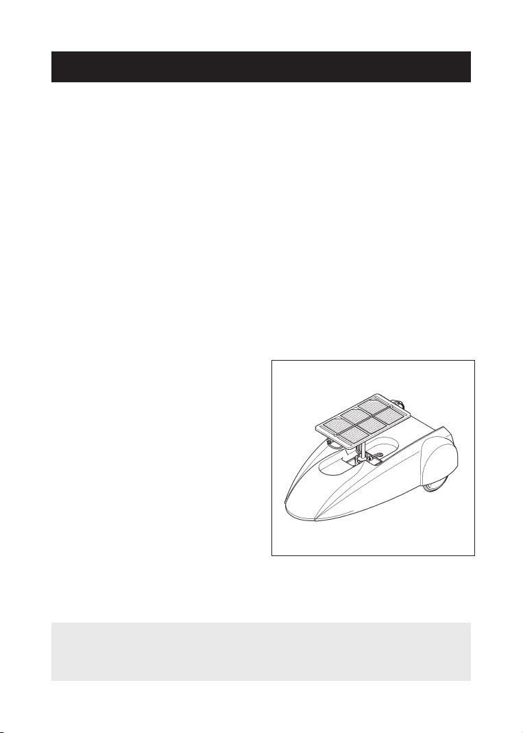
●ProductInformation・T he SUPER SOLAR CAR, with its high and low gear mechanisms, is suit-
able for use even in winter.
・T he angle and direction of the solar battery is adjustable, which are the im-
portant factors to decide the amount of power generation.
・U nique front wheel drive style. The steering mechanism will make turning
movement possible.
・T he front wheel, rear wheel and solar battery sections are separately at-
tachable to the body. f you attach them on your favorite material, such as a
plastic bottle, you can make your original solar car. The kit includes a clear
plastic body.
・T he energy source will be chosen from solar and "AA" battery with a switch
lever.
(A battery is not included.)
SpecificationsPower Source:
①Solar Battery
Output Power / 1.4V-350mA(MAX)
Size / 61 ×110mm
②Dry Cell Battery
“AA”Battery (1.5V)×1pc
〔Not included〕Body Size:
Height / Approx. 45mm
Length / Approx. 225mm
Width / Approx. 145mm
DC Motor (Rated Load:4g.cm):
Rated Voltage / 1.9V
Rated Ampere / 145mA
NO E: he CAR may not operate in shady places, dim sunlight and on cloudy
days. It also will not operate under fluorescent lighting; the fluorescent
light is different in quality from sunlight. When using a candescent lamp, put
the lamp near the solar battery in order for the car to run effectively.
4
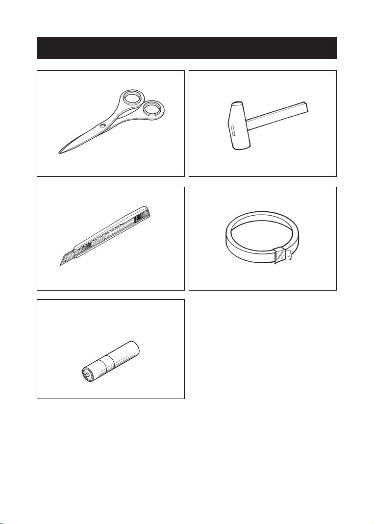
1. NecessaryToolsScissors
Electrical / Plastic Tape
Pen Knife
Small Hammer
“AA”Alkaline Battery(not included)
1 pc
Usedforcuttingadhesivedoublecoat-edtapesandprocessingbodyparts.Usedfordrivingthegearontothemotor.Usedforstrippingthevinylinsulationoffthewire.Usedfortapingexposedwiresandforholdingwiresinplace.

Use the following instructions if you would like to paint the body:
2. BeforeAssembly1. Paint body first and complete assembly process
second.
2. Before painting, wash the plastic body gently with a
detergent and then dry completely.
3. Body part is made of plastic(P.V.C).Use color paints
compatible with plastic models.
4. For graphic designs (writing or drawing) on body,
use an oil based (enamel) marker.
5
CAU ION
◆Pay attention to the following instructions for the use of batteries.
1. Place the batteries in the correct polarity (+ & -).
2. Never short-circuit, dismantle, heat the batteries, or dispose of
them in a fire. They may leak or explode and cause injury.
3. When you finish playing, remove the battery. Exhausted batter-
ies are to be removed from the product.
4. Do not wet the batteries or battery holder. f they get wet, remove
the batteries from the holder and wipe them off thoroughly.
5. Do not mix old and new batteries. Do not mix alkaline, standard
(carbon-zinc) or rechargeable (nickel-cadmium) batteries. Do not
use the rechargeable batteries. Use only the batteries of the
same types as recommended.
※Please carefully follow the instructions supplied by paint manufacture.
6
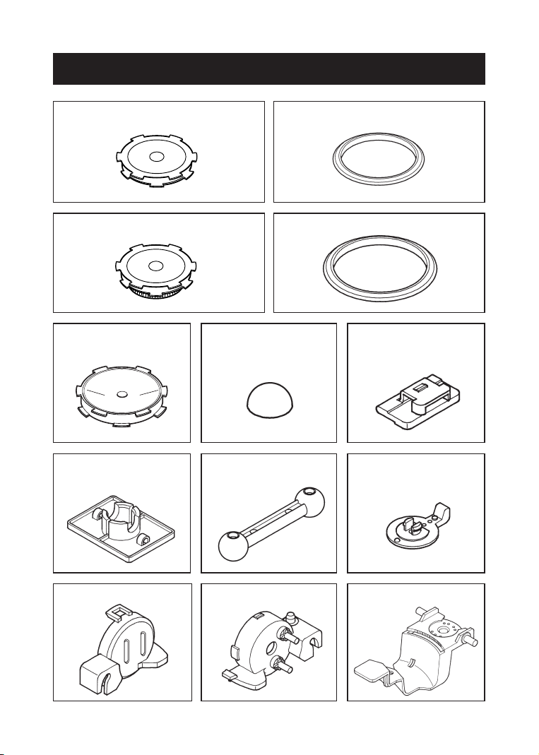
3. PartsListCheck each box to confirm that all parts are enclosed.
□Front wheel (without a gear)
1pc □Front tires
2pcs
□Gear-mounted front wheel 1pc □Rear tires 2 pcs
□Rear wheels
2 pcs □Wheel stoppers
2 pcs
□Solar battery pedestals
2 pcs □Drive shaft stopper
1 pc
□Solar battery support
1 pc □Switch lever
1 pc
□Motor cover 1 pc □Power panel 1 pc □Power chassis 1 pc

□Rear chassis 1 pc □Motor 1 pc
□Flat spur gear (24cogs)
with pinion (12 cogs) 1 pc □Metal shaft 1 pc
□SOLAR CAR body 1 pc
□A dhesive double
sided tape 1 pc □Red wire 1 pc
□Black wire 1 pc □Battery box 1 pc
7
□Solar battery 1 pc
8
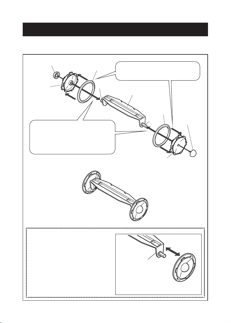
4. Assembly1. Assembling the rear wheels
Assemble the rear wheels in order of steps ①to ②.
Whenremovingthewheels, hold thissec-tionfirmlyandcarefullyremovethewheelstoavoidbreakingtherearchassis. After assembling the rear wheels,
check to see whether the wheels
spin freely. f they do not spin
easily, pull and push on the
wheels with the stoppers attached
to loosen the wheels.
IllustrationofthecompletedrearunitWheelstopperReartireRearwheelRearchassis①Attach the rear tires onto the
rear wheels. WheelstopperRearwheelReartireShaftShaft②nsert the assembled wheels
onto the shafts on the rear
chassis, then attach the wheel
stoppers.

9
2. Attaching the front wheels and the motor
Illustrationofthecompletedfrontwheels1) Assemblethefrontwheelsbyfollowingsteps①and②.Frontwheel(withoutagear)FronttireFronttireGear-mountedfrontwheelMetalshaft①Attach the front tires to the gear-mounted
front wheel and the other front wheel with-
out a mounted gear. ②nsert the wheels, which
are fabricated in step ①,
onto the metal shaft.
1 Gently tap the shaft into
one of the front wheel.
2 Next, gently tap the other
front wheel onto the shaft as
illustrated.
IncorrectCorrectBe sure to stand the metal shaft vertically and tap. When the
shaft is not tapped vertically the wheel might break or crack.
GentlytapthemetalshaftwithasmallhammerStandthemetalshaftverticallyMetalshaftFrontwheel(withoutagear)GentlytapthewheelontotheshaftwithasmallhammerStandthemetalshaftverticallyMetalshaftGear-mount-edfrontwheelncorrect tapping
causes a break
or a crack of this
part.
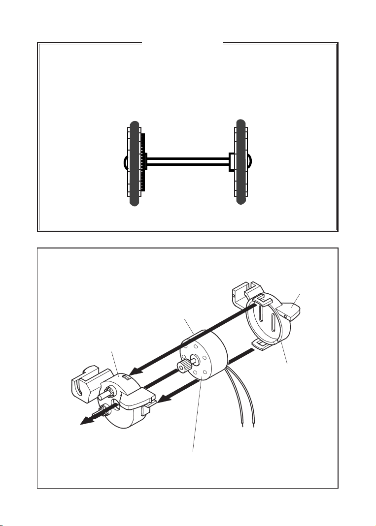
2) Attachthemotoras shown.Runthemotorwirethroughthiscut-out.*Align the hole made in the middle of the motor with the projected
part provided on the reverse side of the power panel.
PowerpanelMotorMotorcoverIMPORTANTGently tap in the front wheels, so that the wheel assembly come to
match the wheel width as illustrated. The distance illustrated is the actu-
al size of the wheel assembly.
f the assembly is too wide, the gears may not engage well , and will not
operate correctly.
Actual size
10

3) Attachtheflatspurgearwithpinionas below. (Setthegearbyselectingeitherlow-speedorhigh-speedrotation.)*Carefully see the illustration when fitting the flat spur gear with pinion, because the fitting
direction of the flat gear is different between “ L” and “ H ” (face and reverse) rotations.
Fit the flat spur gear with pinion into
the boss which has an “H” marking.
*Settingtheflatgeartothehigh-speedrotationwilldecreasethepowerofrun-ning, butthespeedwillrise. Sothehigh-speedwouldbebettertouseonclearandstrong-sunlightsummerdays, when generatingcapacityofthesolarbatteryisincreased.When setting the high-speed rotation
Attach the flat spur gear with pinion to
the boss which has an “L” marking.
*Settingtheflatgeartothelow-speedrotationwillslowdownthespeedofrunning, butthepowerwillbein-creased. Sothelow-speedwouldbeabetterselectiontoruntheCARoncloudyandweak-sunlightwinterdays.When setting the low-speed rotation
4) Mount the power chassisin orderof steps ①to③.Mounting would be easier if the
power panel was opened a little
as shown below. ②nsert the power
panel projected
part (rear) into
the curved
opening in the
power chassis.
※ Note positionof gear※ Note positionof gear③nsert the power
panel projected part
(front) and the boss
on the bottom into
the opening and the
round hole of the
power chassis.
*Recheckthefit-tingstoseeifallthepartshavebeenproperlyseat-edinplace.①Run the motor wire
through this hole.
11

12
5) Mount the front wheelin order of①to②.Driveshaftstopper*Watchtheorientationwheninsert-ing.*Align the gear-mounted front wheel, so that it engages the spur gear
on the motor
Illustrationofthecompletedfrontwheelunit①nsert the front wheel
shaft into the groove. ②nsert the drive shaft
stopper as shown.
Frontwheel
13
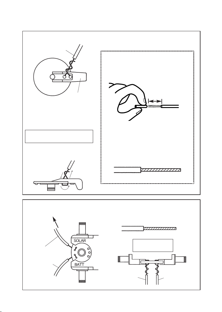
3. Wiring
1)RoutingthewiretotheswitchleverMotorwire(red)Switchlever*Makesurenottowiretheswitchleverthewrongway.Theleverhasafaceandareverse.Putthewirethroughthetwoholesintheswitch lever, thentwisttheexposedwirestogether.2 cm(Approx. 3/4”)Alsoremovetheinsula-tionfrombothredandwhite(orblack) wire.②After removing, twist the stripped
wire.
①Removetheinsulationonthemotorwireapprox. 3/4”more.2)RoutingthewiretothefrontwheelunitRedwire(Loose)Batteryboxwire (red/+) *Twistthestrippedwire.BATTsideSOLARsideFromthebat-terybox(red)Fromthesolarbattery(LooseRedwire)Tothe terminal(+) ofthesolarbatteryllustration seen
from the side
llustration seen from
the side
14
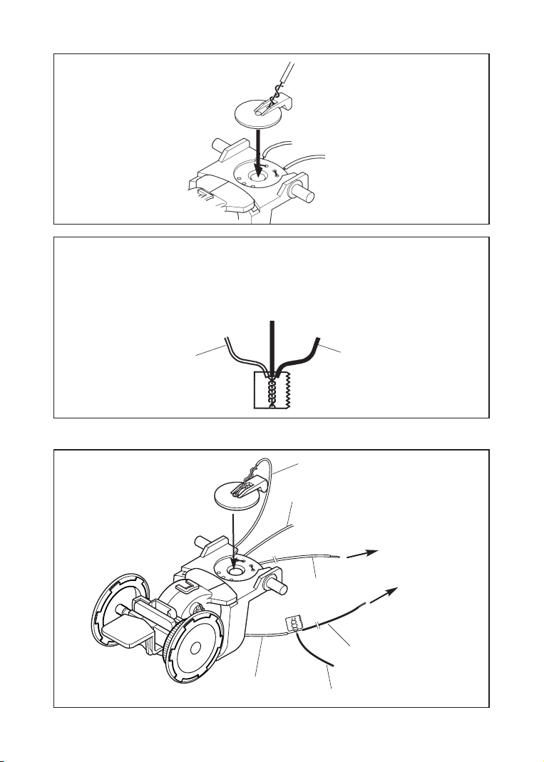
4) Combining the wiresMotorwire(whiteorblack)Combine the exposed ends of the three wires (white / black motor wires,
black battery box wire and the loose black wire) by twisting them together,
then completely tape the exposed wires with electrical tape together.
Motorwire(whiteorblack)LooseblackwireTothesolarbat-teryterminal(+)Tothesolarbat-teryterminal(-)RedwireBatteryboxwire(red / +) Motor wire (red) Batteryboxwire(black/ -)4. Wiring diagram
3) Attaching the switchleverLooseblackwireBatteryboxwire(black/ -)SolarBatteryBatteryBox

15
5. Attachment of the front and rear wheels to the body
Stick the front and rear wheel units
to the inside of the body by using
the double sided adhesive tape.
*Carefullyaligntheunitasillustrated. Then, at-tachtheunittothebodywiththedoublesidedadhesivetape.InserttheRedandBlackloosewiresthroughthishole.●P ositions at which to stick the
adhesive double sided tape ●he illustration below shows
the correct attachment of the
wheel units.
Cutthetapetoanap-propriatesizeforuse.PositiontostickthefrontwheelunitPositiontosticktherearwheelunit*Be careful not to allow the tires to touch the body.
*Becarefulnottolettheadhesivetapetouchthebosses.Bosses
16
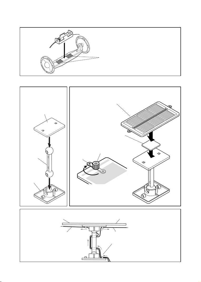
7. Attachingthe solarbattery1) Assemblethebatterystandasshown.2)Attachthesolarbatteryasshown.Solarbattery*Cutthetapetoanappro-priatesize.SolarbatterypedestalSolarbat-terysup-port*Attachthebat-teryinthecenter.3) Wirethebatterystandasshown.Solarbattery (+) sideRedwireSolarbattery (-) sideBlackwireRoutethewirecomingoutofthebodyasillustratedbelow.6. Attaching the battery boxAttach the battery box at this
position, using an adhesive
double sided tape.
AdhesivedoublesidedSolarbat-terypedestal1.Loosen the nut(s)
2.Rotate and expose the terminal(s)
3. ighten the nut(s)
Nut
Backside
Terminal

17
4) Wiretheblackandredwireontothesolarbatteryasshown.As in the illustration, wire the black and red wire into the
terminal metal fitting provided on the solar battery.
Twist it manytimes, so thatthewirewillnotcomeloose.
Makesuretotightenupthenut.Otherwiseitwillnotoperate.
Solar battery terminal (+) →Red wire
Solar battery terminal (−) →Black wire
*Tapetheexcesswirestotheinsidesurfaceofthebodytokeepthewiresfrominterferingwiththemovements.5) Attachthesolar bat-teryunittothebodyasshown.*Cutthetapetoanappropriatesizetouse.Stickthetapehere.CompletedSketchAdhesivedoublesidedtape

5. Let’s Operate!
ATTENTION●Before operating the CAR, check again for incorrect wiring and attachment of
parts. Errors in wiring and attaching the parts may lead to malfunction of the
CAR.
●N ote that the CAR will not run on the cloudy days or in the shaded
places, or under the light of a fluorescent lamp, which has a different
light from that of the sun. Under the light of the candescent lamp, the
CAR can run if the lamp is placed near the solar battery.
●I f the CAR does not run, check again for any incorrect wiring or
whether parts are fitted in wrong locations or directions.
●D o not to allow the CAR to get wet. Failure to prevent this may
cause the unit to become inoperative.
●D o not use or keep the CAR in dusty places or where temperature fluc-
tuates too high and low. Failure to do so may result in malfunction.
18
※ Howtoinstallthebattery.nstall 1pc of “AA” alkaline battery in a battery box, observing
correct polarity (+and − ).

19
Solarcellbatterymode1) Turn ontheswitch.Rotatetheswitchto-wardSOLARorBATT.2) Adjusttheangle sothesunlightshinesontothesolarbat-teryatrightangles.1. How to operate the CAR
“AA” batterymodeSolarbatterymode“AA”batterymode3) Placethe CAR on the ground andoperateit.*The front wheels can turn right and left (steering mechanism). This
mechanism is used to cause the CAR to run in a circle.
With the switch lever properly fitted,
turning the lever toward the SOLAR
side sets the CAR ready for running by
the solar battery. Turning the lever to-
ward the BATT side sets the CAR ready
for running by the battery. n the battery
position, you can run the CAR even in
dark areas. IncorrectCorrect

20
2. Ideas to custom build your CAR
Howtoraiseorlowerthebody.◆T here are two ways to attach the wheels as shown below. (The illustra-
tions below show the side views of the front and the rear wheel units.)
ToraisethebodylevelTolowerthebodylevelCarbodyCarbodyYou can create your own original SOLAR
CAR by sticking the front-rear wheel units
and solar battery unit to a plastic soda
bottle as shown.
◆To make a car body smaller
Attach the rear
wheel here and
fasten it with a
wheel stopper.
Table of contents
Popular Motorized Toy Car manuals by other brands


Jamara
Jamara Jeep Wrangler JL instructions

Fisher-Price
Fisher-Price Power Wheels V4343 Owner's manual with assembly instructions

THUNDER TIGER
THUNDER TIGER TOMAHAWK ST manual

Kyosho
Kyosho GP TR-15 RALLY 4WD instruction manual

Eduard
Eduard Sd.Kfz.9 "FAMO" quick start guide

Power Wheels
Power Wheels Jeep Junior 74240 Owner's manual with assembly instructions

Hunter Products
Hunter Products TR1529 owner's manual

CyClone
CyClone D4 instruction manual

Ripmax
Ripmax Husky C-RMX0020 - UK operating instructions

Hunter Products
Hunter Products TR1305 Service guide

RUSTA
RUSTA Race car manual

Fisher-Price
Fisher-Price Power Wheels 77760 Owner's manual with assembly instructions