Elekit Movit Spin Shooter User manual
Lot.No.
9002E-04
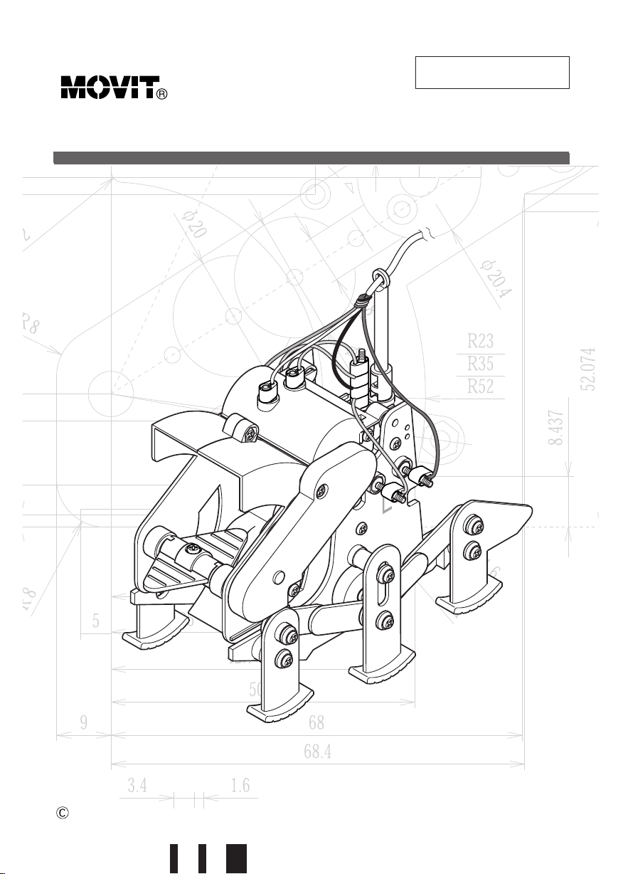
SPINSHOOTERMODEL: MR-9002E
EK JAPAN CO., LTD. 2001
2
Contents
● Product Information ‥‥‥‥‥‥‥‥‥‥‥‥‥‥‥‥‥‥‥‥‥‥‥‥‥‥‥‥‥‥‥‥‥‥3
Ⅰ. Assembly of Mechanical Parts
1. Necessary Tools for Mechanical Assembly‥‥‥‥‥‥‥‥‥‥‥‥‥‥‥‥‥‥‥4
2. Before Assembling Mechanical Parts ‥‥‥‥‥‥‥‥‥‥‥‥‥‥‥‥‥‥‥‥‥4
3. Parts List‥‥‥‥‥‥‥‥‥‥‥‥‥‥‥‥‥‥‥‥‥‥‥‥‥‥‥‥‥‥‥‥‥‥‥‥‥‥‥‥6
4. Assembly of Controller‥‥‥‥‥‥‥‥‥‥‥‥‥‥‥‥‥‥‥‥‥‥‥‥‥‥‥‥‥‥‥8
5. Assembly of Body ‥‥‥‥‥‥‥‥‥‥‥‥‥‥‥‥‥‥‥‥‥‥‥‥‥‥‥‥‥‥‥‥‥12
6. Let’s Operate!‥‥‥‥‥‥‥‥‥‥‥‥‥‥‥‥‥‥‥‥‥‥‥‥‥‥‥‥‥‥‥‥‥‥‥‥22
7. How to Play ‥‥‥‥‥‥‥‥‥‥‥‥‥‥‥‥‥‥‥‥‥‥‥‥‥‥‥‥‥‥‥‥‥‥‥‥‥23
Ⅱ. Technical Data
1. Explanation of Controller‥‥‥‥‥‥‥‥‥‥‥‥‥‥‥‥‥‥‥‥‥‥‥‥‥‥‥‥‥24
2. Explanation of Mechanism ‥‥‥‥‥‥‥‥‥‥‥‥‥‥‥‥‥‥‥‥‥‥‥‥‥‥‥26
Ⅲ. Explanation of Molding
1. Molding Procedure ‥‥‥‥‥‥‥‥‥‥‥‥‥‥‥‥‥‥‥‥‥‥‥‥‥‥‥‥‥‥‥‥28
2. Molded Plastic Parts ‥‥‥‥‥‥‥‥‥‥‥‥‥‥‥‥‥‥‥‥‥‥‥‥‥‥‥‥‥‥‥30
Ⅳ. Explanation of Motors
1. History of Motors‥‥‥‥‥‥‥‥‥‥‥‥‥‥‥‥‥‥‥‥‥‥‥‥‥‥‥‥‥‥‥‥‥‥32
2. Motor Mechanisms ‥‥‥‥‥‥‥‥‥‥‥‥‥‥‥‥‥‥‥‥‥‥‥‥‥‥‥‥‥‥‥‥32
3. Types of Motors ‥‥‥‥‥‥‥‥‥‥‥‥‥‥‥‥‥‥‥‥‥‥‥‥‥‥‥‥‥‥‥‥‥‥34
V. Explanation of Screws
1. Discovery of Screws ‥‥‥‥‥‥‥‥‥‥‥‥‥‥‥‥‥‥‥‥‥‥‥‥‥‥‥‥‥‥‥36
2. Types and Sizes of Screws ‥‥‥‥‥‥‥‥‥‥‥‥‥‥‥‥‥‥‥‥‥‥‥‥‥‥‥36
3. How screws are used‥‥‥‥‥‥‥‥‥‥‥‥‥‥‥‥‥‥‥‥‥‥‥‥‥‥‥‥‥‥‥38
Ⅵ. Spare Parts List ‥‥‥‥‥‥‥‥‥‥‥‥‥‥‥‥‥‥‥‥‥‥‥‥‥‥‥‥‥‥‥‥‥39
◆R ead this instruction manual carefully before getting started. Have your parents or someone
who can help you read the instruction manual with you. Keep this instruction manual for fu-
ture reference.
◆B e careful when handling the tools such as a penknife and a diagonal cutter.
◆H andle the small and sharp parts carefully.
◆K eep the product out of reach of small children. Do not assemble the product where small chil-
dren can reach and touch it. They may get injured or put the parts / small vinyl bags into their
mouth. mmediately dispose of the packaging materials and the left over parts sensibly.
◆D o not short-circuit the printed circuit board, electronic parts, or power supply terminals. t will
result in overheating of the parts and batteries, causing injury and fire.
◆D o not insert the wires into socket outlets. t will cause damage and injury.
◆K eep fingers out of the moving sections, such as wheels, legs, gears and motor shafts.
◆D o not hinder the movement of moving sections by force. Remove the hindrances in the
moving sections, such as a piece of thread, before operating. Otherwise, the motor will over-
heat, causing injury and fire.
◆T he specifications and forms of this product are subject to change without prior notice.
PRECAUTIO
●ProductInformation
●Product nformation
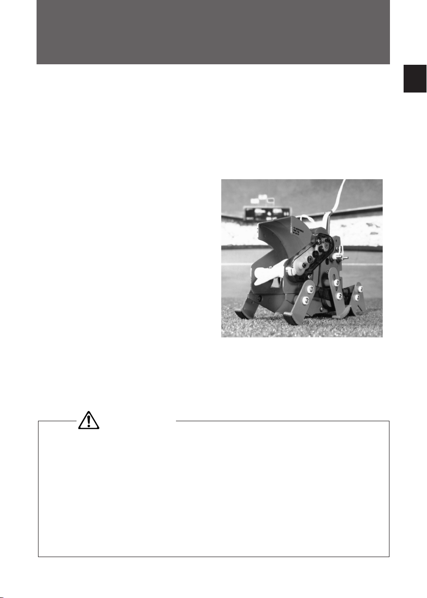
●Outline
SP N SHOOTER is a do-it-yourself mechanical kit to make a six-legged machine with three
motors, operated by a wired controller.
The moving features of SP N SHOOTER are: forward, backward, right and left turns, made by
its controller. With the motor in the shooting system, it can throw the ball powerfully to get a
goal. Creative performance fields and rules will make your game more exciting.
●Specifications
Power Source / “AA” alkaline battery X 4 pcs
(not included)
Power Consumption / Maximum approx. 900 mA
(when all three motors operating)
Approx. average 550 mA
Battery Duration / Approx. 2.5 hours
(continuous operation average)
Size / Body: W85 X H140 X D170 (mm)
(projection not included)
Controller: W95 X H126 X D31 (mm)
(projection not included)
Wire: 2m
SPI SHOOTER MR- 9002E
Certain technical terms are used in this instruction
manual due to give you specific knowledge about
electronics and mechanics, which will help you to
understand other technical texts in the future. 【Colored example】* For coloring the machine, carefully read the
“ otes for coloring” on page 40, in advance.
3
CAUTIO
◆P ay attention to the following instructions for the use of batteries.
1. Place the batteries in the correct polarity (+ & -).
2. Never short-circuit, dismantle, heat the batteries, or dispose of them in a fire. They may leak
or explode and cause injury.
3. When you finish playing, remove the battery. Exhausted batteries are to be removed from
the product.
4. Do not wet the batteries or battery holder. f they get wet, remove the batteries from the hold-
er and wipe them off thoroughly.
5. Do not mix old and new batteries. Do not mix alkaline, standard (carbon-zinc) or recharge-
able (nickel-cadmium) batteries. Do not use the rechargeable batteries. Use only the bat-
teries of the same types as recommended.

4
Ⅰ.
AssemblyofMechanicalParts
1. ecessary Tools for Mechanical Assembly
Hammer
Pen Knife
Use for installing pinion gears,
etc.
Use for cutting off unneces-
sary projections and burrs.
Screwdriver (M3)
Use for turning screws.
Long-nose Pliers
2. Before Assembling Mechanical Parts
• Molded Parts
Detach all the parts from the runners with a diagonal
cutter and cut off unnecessary projections neatly. They
may affect the function of the product. Please scrape
them off thoroughly with a penknife or a file.
Use for handling parts and hold-
ing nuts when screwing.
Diagonal Cutter
Use for cutting parts out of
the frame.
“AA” alkaline battery X 4 pcs
Batteries (not included)
Ⅰ. Assembly of Mechanical Parts

5
Ⅰ. Assembly of Mechanical Parts
• Driving shaft into gears
The motor shaft must be pressed into gears. To reduce
the shock and protect the gears and cranks, using a
lever is recommended. However, if one is not available,
tap the gears and cranks gently so as not to damage
them. Please pay careful attention to the procedure.
The flat side
• Parts made of Rubber
Parts made of rubber will stretch. Be careful not to stretch
them too much or they will break.
Use a diagonal cutter to detach the parts.
• Tightening the lock nut
Lock nut is a special kind of nut, which has a nylon ring
inside in order to prevent the nut from becoming loose
while the assembled kit is operating. When screwing in-
to a lock nut, its direction is important : it needs to be
screwed from the flat side of the nut. When screwing in-
to a lock nut, more power is needed compared to a reg-
ular nut. Use a screwdriver with a bigger handle, so that
the power for turning the screw is used more efficiently.
Use long-nose pliers or a nut driver to hold the nut, when
screwing.
• Tightening of nuts and screws
Tighten nuts and screws properly, or they may come
loose. Overtightening may also cause damage. Tight-
en them just enough to work properly.
Nut driver
6
Ⅰ. Assembly of Mechanical Parts
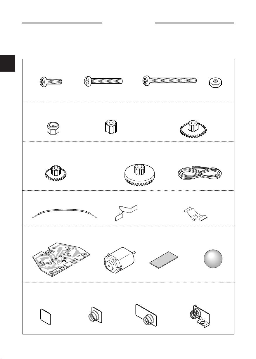
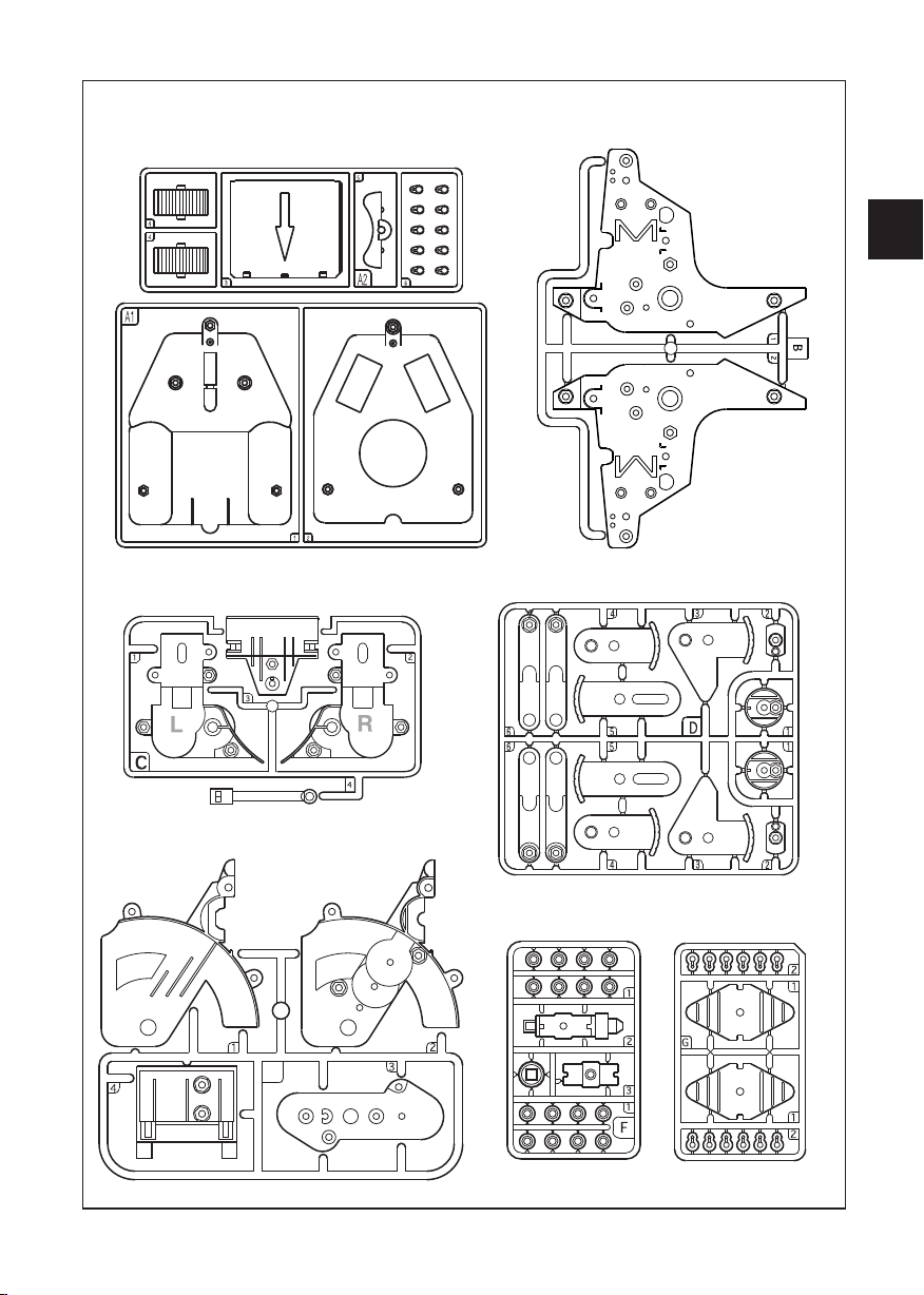
3. Parts List
* Check the parts by marking a blank box.
* Some parts may have lines called weld lines formed through the resin treatment.
They have no effects on assembly and function.
qNut 54pcs
qPrinted Circuit Board 1pc
qSwitch contact A 1pc qSwitch contact B 2pcs
q4-line wire 1pc
qWire 3pcs
qFlat spur gear with pinion
(small) [24 teeth, 12 teeth]
4pcs
q
Crown gear with pinion
[36 teeth, 12 teeth] 2pcs
q
Flat spur gear with pinion
(large)
[36 teeth, 12 teeth] 7pcs
qPinion gear [12 teeth] 3pcs
qLock nut 2pcs
qScrew (small) 48pcs
qMotor 3pcs qFoot sticker 1sheet qBall 1pc
qScrew (medium) 8pcs qScrew (large) 1pcs
* Spare Parts: There may be extra screws and nuts. Keep and use them as spare parts.
qBattery contact
for positive 1pc
qBattery contact
for negative 1pc
q
Battery contact
for + and - 3pcs
qBattery contact
for PCB 3pcs
7
Ⅰ. Assembly of Mechanical Parts
qController set (A1) 1pc
(A2) 1pc
qSet B 1pc
qSet C 1pc
qSet E 1pc
qSet D 1pc
qSet F 1pc qSet G 1pc
E

8
Ⅰ. Assembly of Mechanical Parts
qNut 10pcs qBattery contact
for positive 1pc
q
Battery contact
for + and - 3pcs
qBattery contact
for negative 1pc
①AssemblyofPCboardandbatteryholder
qScrew (small)
10pcs
qBattery contact
for PCB 3pcs
*Check the parts by marking a blank box before assembling.
qA2-3
4. Assembly of Controller
※※※※※※※
PC Board
(the side with descrition here)
Screw (small)
Screw (small) / 3pcs
A2-3
Battery contact
for positive
Battery contact
for negative
Battery contact +/-
Battery contact
for + and -
※Attach the screws and nuts tightly
at the seven ※marked spots.
※B e sure to attach the battery contacts in proper directions.
Nut
Nut / 3pcs
Battery contact
for PCB / 3pcs
The side with the slot
Tighten the
screws firmly!
qPC Board

9
Ⅰ. Assembly of Mechanical Parts
② AttachmentofPCboardand4-linewireqA1-1
A1-1
qSwitch contact B 2pcs
Switch contact B
4-line wire
Penetrate 4-line wire through both the PC board
and the case.
Side View
The side with shorter colored wires
The side with longer colored wires
Put 4-line wire through the hole at the bottom of A1-1.
qScrew (small) 2pcs
Screw (small)
Tighten the
screws firmly!
qNut 2pcs
Nut
q4-line wire
qAssembled PC Board from ①
10
Ⅰ. Assembly of Mechanical Parts
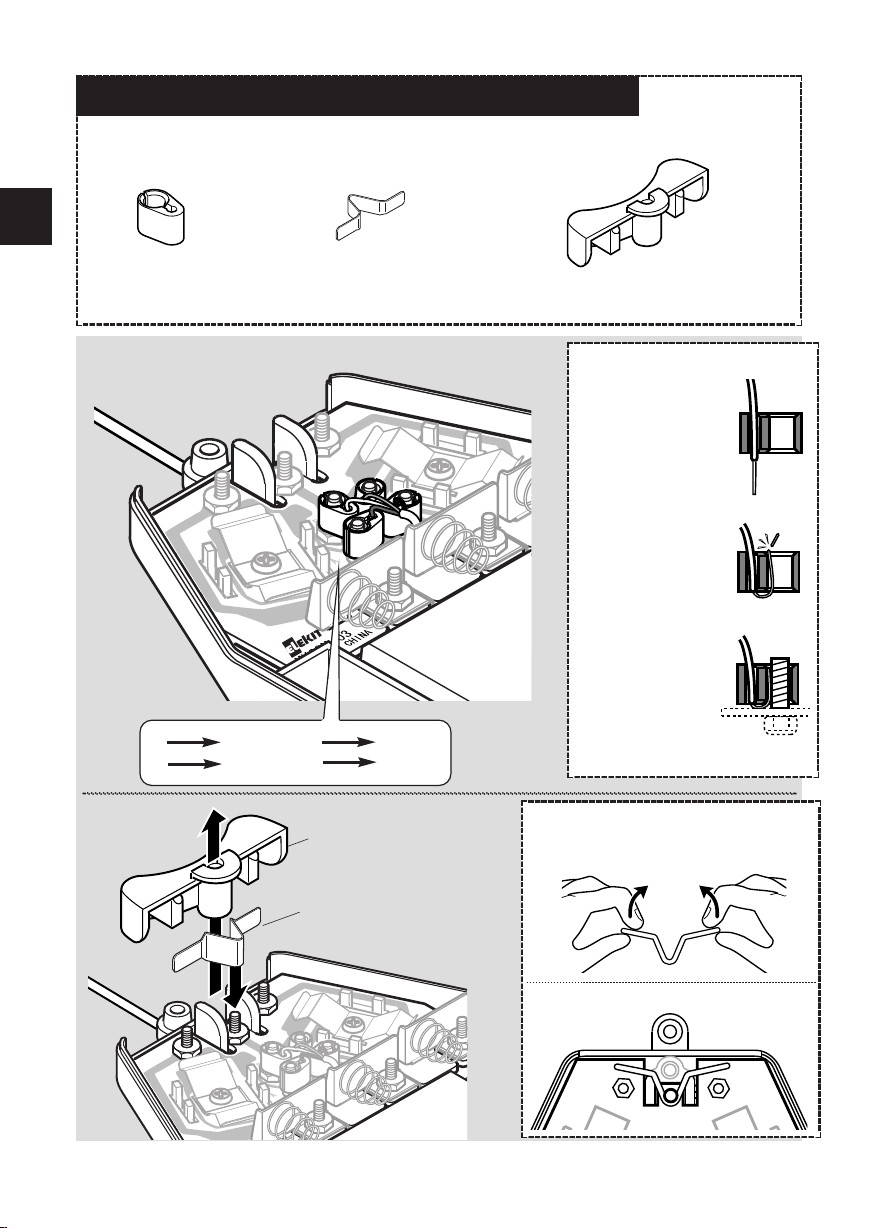
③ WiringofPCboardandattachmentofrotorswitchqA2-6 4pcs qSwitch contact A 1pc
Switch contact A
qA2-5
A2-5
Pull out the 4-line wire. How to attach the wires
A
B
CD
1) Put the wire
through the small-
er hole of A2-6.
2)
Only bend the
stripped end of the
wire and put it into the
larger hole of A2-6.
When the wire sticks
out from the hole, trim
it with a diagonal cut-
ter.
3) Attach the A2-6
to the respective
screw, inserting
it into the larger
hole with the
stripped end.
Top view of switch contact A
How to attach the contact A
Bend both ends as shown a little to fit it in.
*Do not bend too much.
A Red C Green
B White D Black

11
Ⅰ. Assembly of Mechanical Parts
④ AttachmentofuppercoverqScrew (small) 3pcs
Screw (small) / 3pcs
Nut / 3pcs
qA1-2
A1-2
qA2-4 2pcs
A2-4 / 2pcs
qNut 3pcs
qAssembled battery holder from ①Do not put in the batteries yet.
Otherwise, the ends of the 4-line
wire may short and cause excess
heat, explosion or fire to the bat-
teries.
Match the slit of
the case and
battery holder.
Caution!Side View
Push the battery
holder until it is
hooked.
Battery holder

12
①AttachmentofMotorqPinion gear 3 pcs
Pinion gear
C-2
Makethreesetsofthefollowing.qMotor 3pcs
Motor
Flush to the surface.
* The terminal side of the motor faces
outward.
* Attach the motors fully and firmly.
qC-1 1pc qC-2 1 pc
Attach two of the three motors to C-1 and C-2.
* Bend the terminals
upward about 45 °
Ⅰ. Assembly of Mechanical Parts
5. Assembly of Body
C-1
13
Ⅰ. Assembly of Mechanical Parts
qNut 8 pcs
qScrew (medium) 6 pcs
qLock nut 2 pcs
qD-1 2 pcs qD-2 2 pcs
qFlat spur gear with
pinion (large) 2 pcs
qB-1 1 pc qB-2 1 pc
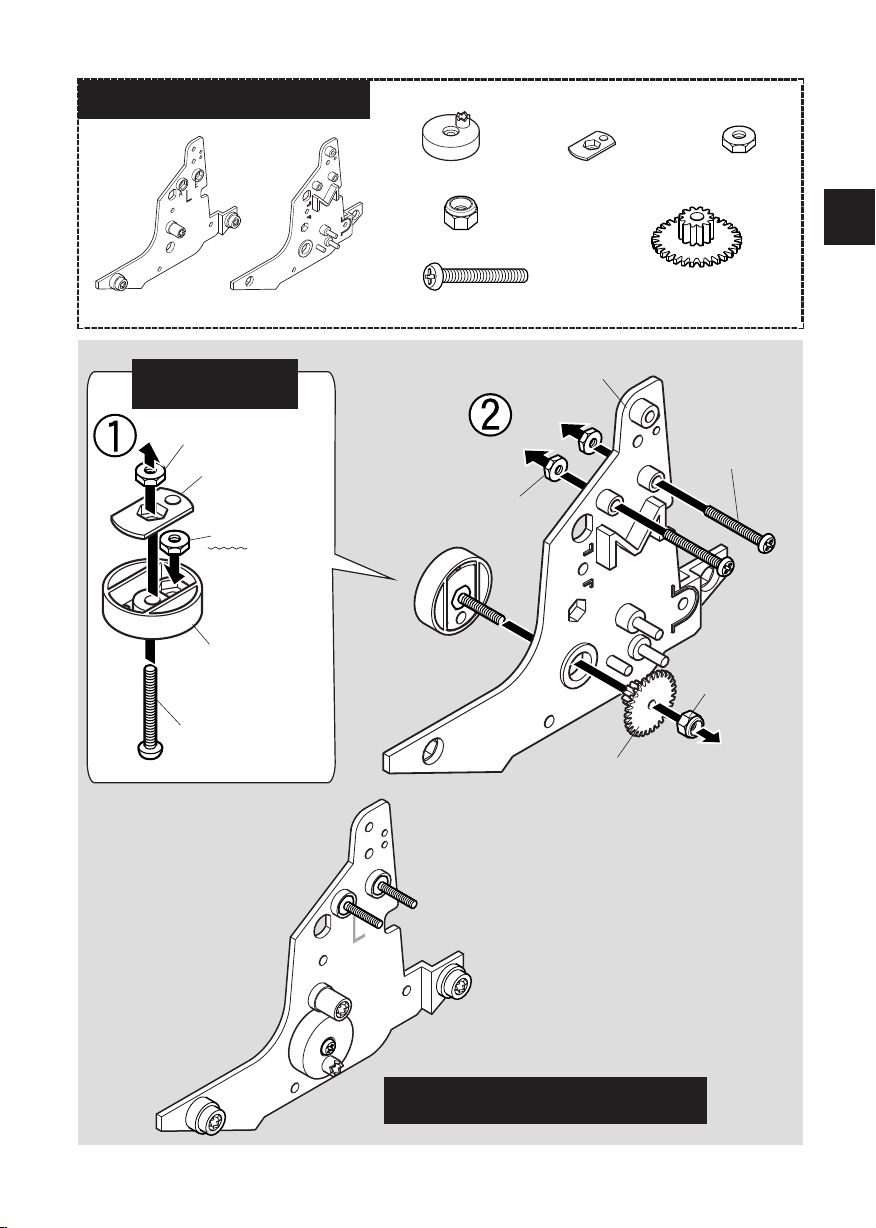
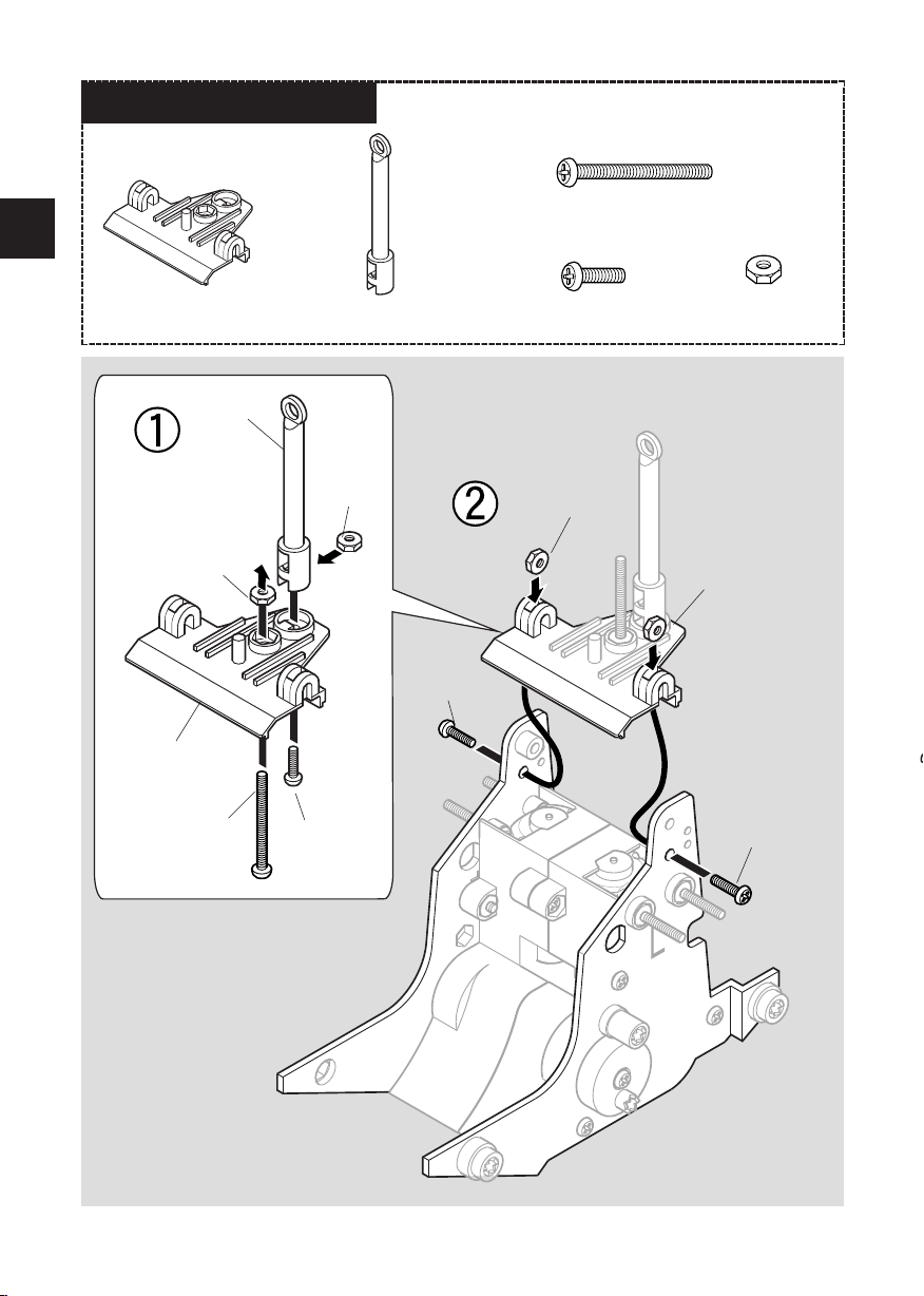
② AssemblyofsidepanelNut / 2 pcs
Nut
* Do not forget
to attach it!
Screw (medium)
Screw
(medium) / 2 pcs
Lock nut
D-1
D-2
* Make sure of
the direction.
Flat spur gear with pinion (large)
Assembletheleftside(B-1)usingthesamemethod.* Please refer to the page 5 for
how to tighten a lock nut.
B-2
Make2 setsofthefollowing.Nut

14
Ⅰ. Assembly of Mechanical Parts
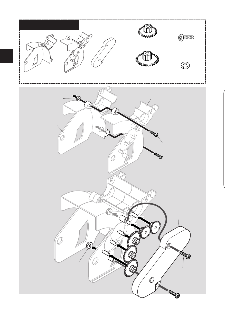
③ AssemblyofgearboxC-2
qCrown gear with pinion 2 pcs
qFlat spur gear with
pinion (small) 2 pcs
qFlat spur gear with pinion
(large) 2 pcs
[2] Flat spur gear with pinion (large)
qNut 6 pcs
qScrew (small)
6 pcs
Screw (small) / 3 pcs
qAssembled side panel R, L from ②qAssembled gearbox from ①Assembletheleftside(B-1) usingthesamemethod.Attach the parts in order from [1] to [3]
[1] Flat spur gear with
pinion (small)
Nut / 3 pcs
[3] Crown gear with pinion
Make sure that the motor terminals con-
nect with the screw heads as shown.
15
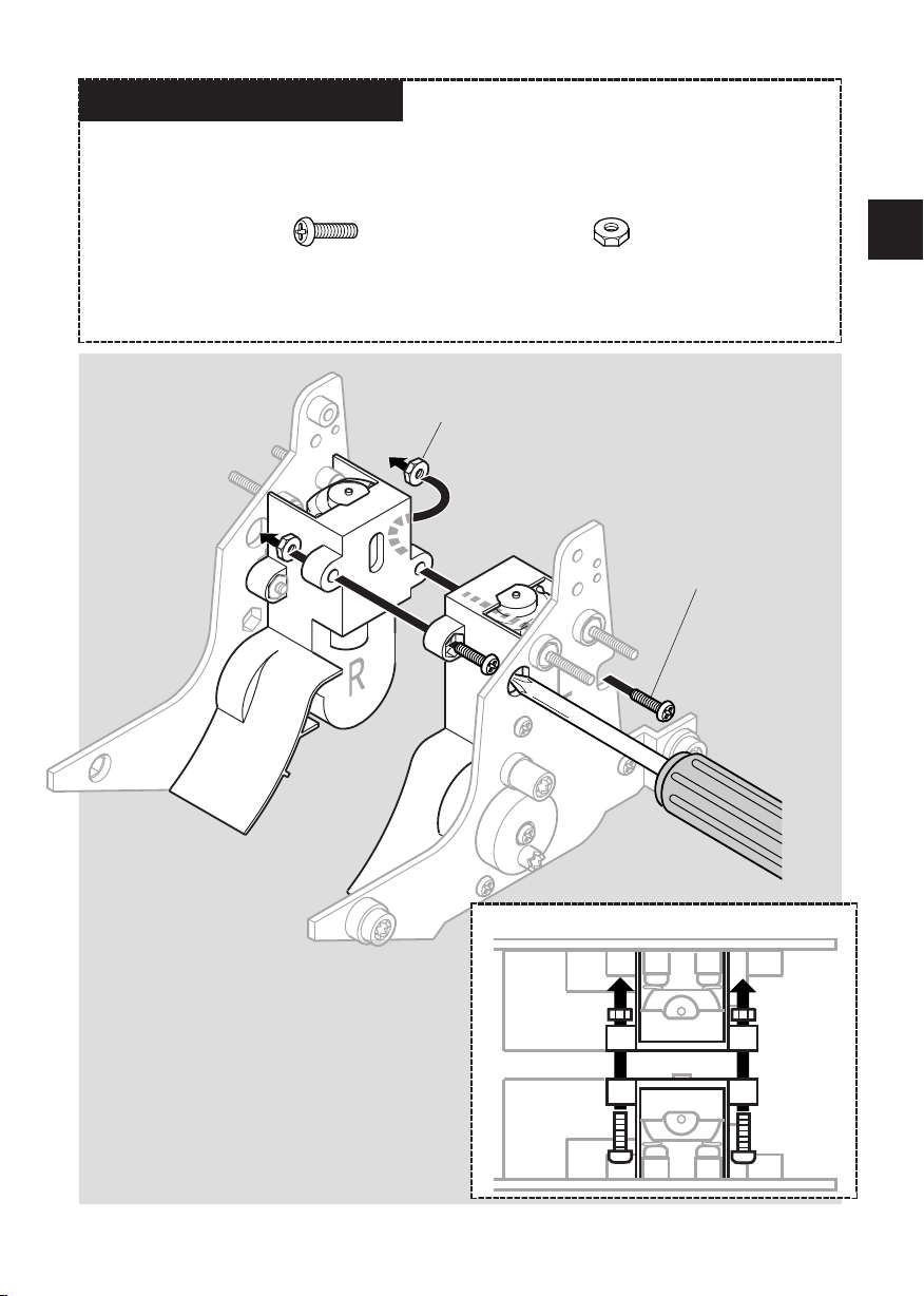
④AttachmentofsidepanelsqAssembled side panels R, L from ③qNut 2 pcs
Nut / 2 pcs
qScrew (small) / 2 pcs
Screw (small) / 2 pcs
Top view
Ⅰ. Assembly of Mechanical Parts
16
Ⅰ. Assembly of Mechanical Parts
⑤AssemblyoftoppanelqScrew (large) 1 pc
qC-3 1pc qScrew (small) 3 pcsqC-4 1 pc qNut 4 pcs
qAssembled unit from ④1 pc
C-4
C-3
Nut Nut
Nut
Nut
Screw (small) Screw
(small)
Screw
(small)
Screw (large)

17
Ⅰ. Assembly of Mechanical Parts
⑥AssemblyoflegsqD-3 D-4 D-5
2 pcs each
qD-6 4pcs
qScrew (small) 10 pcs
qScrew (medium) 2 pcs
Screw (small) /
3 pcs
Screw
(medium)
qNut 10 pcs
qF-1 12 pcs
qAssembled unit from ⑤Assembletherightside(Rmarked)usingthesamemethod.Maketwosetsofthefollowing.D-4 D-3
Screw
(small)
Screw (small)
D-6
D-6
Right rear leg
Front leg
[2] Left rear leg
[3] Middle leg
[1] Front leg
Left rear leg
F-1
F-1 / 4 pcs
F-1
Nut
Nut
Attach the parts in order from [1] to [3].
* Attach the F-1 to the screw before secur-
ing.
* Make sure of
the directions.
* Check to see if the diagram is correct and
the labeling of the right and left rear leg.
18
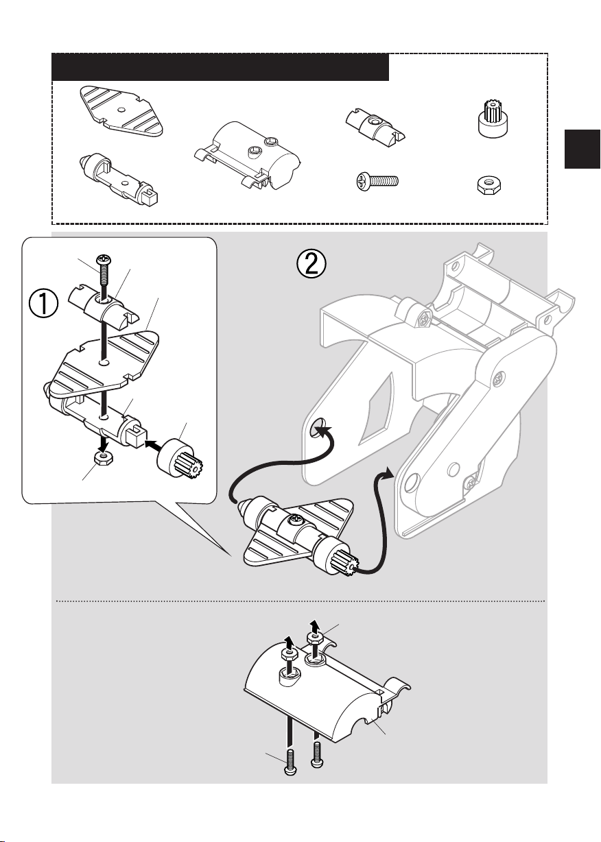
⑦AssemblyofrotorqE-1 1pc qE-2 1pc qE-3 1 pc
E-3
qNut 4 pcs
Screw (small) / 2 pcs
qScrew (small)
4 pcs
Screw (small) / 2 pcs
Screw (small) /
2 pcs
qFlat spur gear with
pinion (large) 3 pcs
qFlat spur gear with
pinion (small) 2 pcs
E-1
E-2
[3]
[4]
[ 5 ]
[1]
[2]
Attach the flat spur gears with pin-
ion (large) in order from [1]〜[3],
and flat spur gears with pinion
(small) in order from [4]〜[5].
Nut / 2 pcs
Ⅰ. Assembly of Mechanical Parts
19
Ⅰ. Assembly of Mechanical Parts
⑧AssemblyofrotorshaftpanelandtoppanelqNut 3 pcs
qF-4 1pc
qG-1 1pc
qAssembled rotor from ⑦qF-3 1pc
qF-2 1 pc qE-4 1pc
E-4
qScrew (small) 3 pcs
F-2
G-1
F-3
Screw
(small)
Screw (small) / 2 pcs
Nut
Nut / 2 pcs
F-4
20
Ⅰ. Assembly of Mechanical Parts
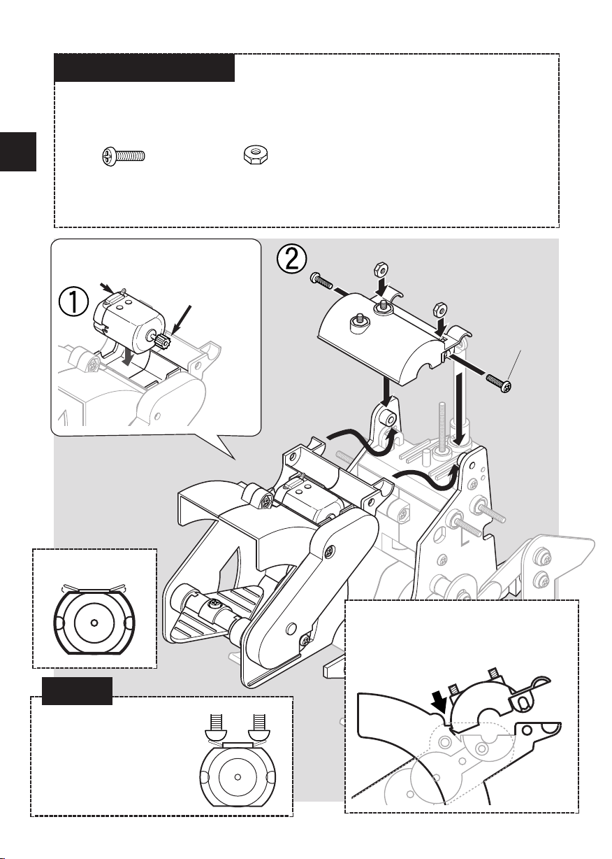
⑨AttachmentofrotorqAssembled rotor and rotor top panel from ⑧qAssembled unit from ⑥qAssembled motor from ①Attach the parts in order from [1] 〜[3]
qScrew (small) 2 pcs
Screw (small) /
2 pcs
Put the motor in the rotor.
Terminal face up. Pinion gear will
come to the gear
side.
[1] [2]
[3]
qNut 3 pcs
* Place the edge of the rotor top panel
under the rib provided on the rotor.
* Bend the terminals
upward about 45 °Make sure that the motor ter-
minals connect with screw
heads firmly, otherwise the
electricity will not be con-
veyed to the motor and the ro-
bot does not work properly.
Attention!
This manual suits for next models
1
Table of contents
Popular Robotics manuals by other brands


McConnel
McConnel Robocut RC56 Operator's manual

ABB
ABB DressPack IRB 6700 product manual

SuperDroid Robots
SuperDroid Robots MiniSLAM Setup, Operation, and Configuration

CMA Dishmachines
CMA Dishmachines GR Series Maintenance manual

TTS
TTS Bee-Bot user guide

Barrett
Barrett Wraptor BH8-610 Series user manual


