elektraLite 1018 User manual

Elektralite LED
1018
USER MANUAL
(Version 4.0)
(From serial number 11915).
Elektralite (a division of Group One),
70, Sea Lane, Farmingdale, NY11735, U.S.A.
T. +1 (631)-396-0184. F. +1 (631)-396-0190
WWW.MYELEKTRALITE.COM

1. Unpacking
Thank you for choosing the Elektralite 1018 fixture. For your own safety, please read this manual
before installing the fixture. This manual covers important information on installation and
applications. Please keep this manual for future reference.
To keep this simple, we are going to refer to the fixture as the Elektralite 1018 throughout the
manual.
The Elektralite 1018 fixture uses 18 high powered leds in a balanced arrangement giving
incredible output. Please unpack it carefully and check whether it was damaged in shipping.
The following items should be in the box with the fixture:- Gel frame, safety glass and safety cable.
2. Safety Instructions.
This device has left the factory in perfect condition. In order to maintain this condition and to
ensure a safe operation, it is absolutely necessary for the user to follow the safety instructions and
warning notes written in this user manual. The Elektralite 1018 is a high voltage fixture. Be careful
when dealing with high voltages.
Please read this manual. If you do not read this manual and damages occur to the
Elektralite 1018, then it could void the warranty.
During shipping, the Elektralite 1018 may have been exposed to high temperature changes or
humidity changes. So, as a precaution, do not switch the Elektralite 1018 on immediately.
Condensation can damage the Elektralite 1018 so leave the Elektralite 1018 switched off until it
has reached room temperature. The Elektralite 1018 is an INDOOR operational fixture. Do not
operate this fixture outdoors or anywhere there is high humidity.
The electric connection must carry out by a qualified person and it is absolutely essential that the
Elektralite 1018 be grounded. So under no circumstances break off the ground pin on the Edison
plug or use the fixture where a ground is not present. A ground pin, like the fuse for the Elektralite
1018 is there for safety.
Always disconnect the Elektralite 1018 from the power source, when the fixture is not in use or
before cleaning it. Elektralite 1018. Never pull out the Edison plug out by just pulling on the power
cord itself.
Please keep the Elektralite 1018 away from children and the general public. Please be intelligent
and use common sense when operating the Elektralite 1018.

3. General Guidelines.
Elektralite 1018 is a lighting fixture for professional use on stages, in clubs, theatres, churches
etc.
Elektralite 1018 should only be operated at between 120 to 240 volts and only indoors.
Elektralite 1018 should not be operated 24/7 (24 hours a day; 7 days a week). Elektralite 1018
needs operation breaks to ensure that it will work for a long time without problems. Please do not
shake the Elektralite 1018 and avoid using brute force when installing or operating it.
When choosing the location to install the Elektralite 1018, please make sure that it is not exposed
to extreme heat, moisture or dust and never install it outdoors. Make sure that the fixture has a
good amount of free space around it for air flow. Do not install it in a confined space or have
insulation around the fixture. The minimum distance between the Elektralite 1018 and the
illuminated surface must be more than 3 feet.
Always mount the Elektralite 1018 with an appropriate safety cable.
Operate the Elektralite 1018 only when you are familiar with the features on the fixture. Do not
permit operation by persons not qualified.
All modifications to the Elektralite 1018 will invalidate the warranty. There are absolutely no
exceptions.
If Elektralite 1018 is operated in any way different to the one described in this manual, Elektralite
1018 maybe damaged and the guarantee will be void
4. Installation
Please ensure that the Elektralite 1018 is hung using the appropriate "C" clamp or half
cheeseboro. A safety chain or cable should also be used as a secondary point of holding the
fixture in case the clamp comes loose. Never hang the fixture without a safety chain or cable.
Make sure the Gel frame (Gel holder) is clipped into position correctly and cannot come loose.
If you are not qualified or have any doubts about hanging the Elektralite 1018 then do NOT hang
it.
Do not clamp the safety cable to the U bracket or clamp. That is not a secondary safety point.
A secondary safety point is any point that will adequately hold the Elektralite 1018 if the "C" clamp
or half cheesboro fails. Then the safety cable would be the backup and stop the fixture from falling
to the ground. So do NOT fix the safety cable to the same place that the "C"clamp is attached.
Installation during construction.
Many times fixtures are installed during the construction phase of a building. It is imperative that
the fixture is protected during this phase. A lot of dust is usually created. This dust can adversely
affect the fixture. Specifically, of course, in coating the lenses and therefore reducing the output.
However much more seriously, dust, like sheetrock dust, can get inside the fan bearings especially
if the fixture is being operated during construction. Sheetrock dust, mixed with the grease of the
fan motor, will result in the fan’s premature failure and that is not covered under the fixture’s
warranty. It is therefore strongly advised to keep the fixtures covered up during the construction
phase and not used.

5. Grounding.
Always make sure that there is sufficient grounding (earth) for the fixture. This is not only
imperative within the circuit that the fixture is being connected to, but also make sure there is
sufficient grounding into the building. All fixtures regardless of manufacturer have a surge at initial
“turn-on”. Once initial “turn-on” is complete, the surge current (per fixture) will travel down the
ground. While each 20 Amp circuit may have the correct size of ground wire, the ground input to
the building and/or electrical panel may not be sufficient for the job. Please review this with the
electrical contractor. The elektraLite 1018 has a surge current over and above its operating
current of approximately 2 Amp at 120 volts. If an installation has 100 1018 fixtures that means
200 Amps needs to be dissipated through the GROUND WIRING. If there is a lack of a sufficiently
big enough ground cable into the building or on the individual circuits it can cause severe damage
to the fixture and this is not covered under the warranty.
One further check : the ground to neutral voltage for each circuit. In a lot of buildings, voltages
across these can damage fixtures or cause operational problems both for the fixture and DMX.
Please review these two important points with a qualified electrical contractor. If in any doubt, have
an independent qualified third party electrical contractor check the installation, well before
commencing installation.
Circuit Limitation:-
There should be no more than 5 Elektralite 1018 on a 20 amp 120 volt circuit, having no other
load on it. That means to say a, maximum of 5 Elektralite 1018 are on a 20 amp 120 volt circuit
with nothing else plugged into that circuit.

6. DMX-512 Control Connection
Connect an XLR cable to the female 5-pin XLR output of your Elektralite CP 20 or other DMX
controller. The other end should be connected to the male 5-pin XLR input of the Elektralite 1018.
Then daisy-chain out of the first Elektralite 1018 into the next Elektralite 1018 or other dmx
device. Never “Y” split the DMX connection.
If you need more cable, then it should be two core, screened cable fitted with a 5 pin XLR input
and output connector. Please refer to the diagram below.
1
2
3
4
5
DMX-512 connection with DMX terminator
For installations where the DMX cable has to run a long distance or is in an electrically “noisy”
environment, it is recommended that a DMX terminator is used. This helps prevent corruption of
the digital control signal. The DMX terminator is simply a 5 pin XLR plug (male) with a 120 Ω
resistor connected between pins 2 and 3. It is then plugged into the output XLR socket of the last
Elektralite 1018 or other dmx device in the chain. Please see illustration below.
1
2
3
4
5
Ω
120

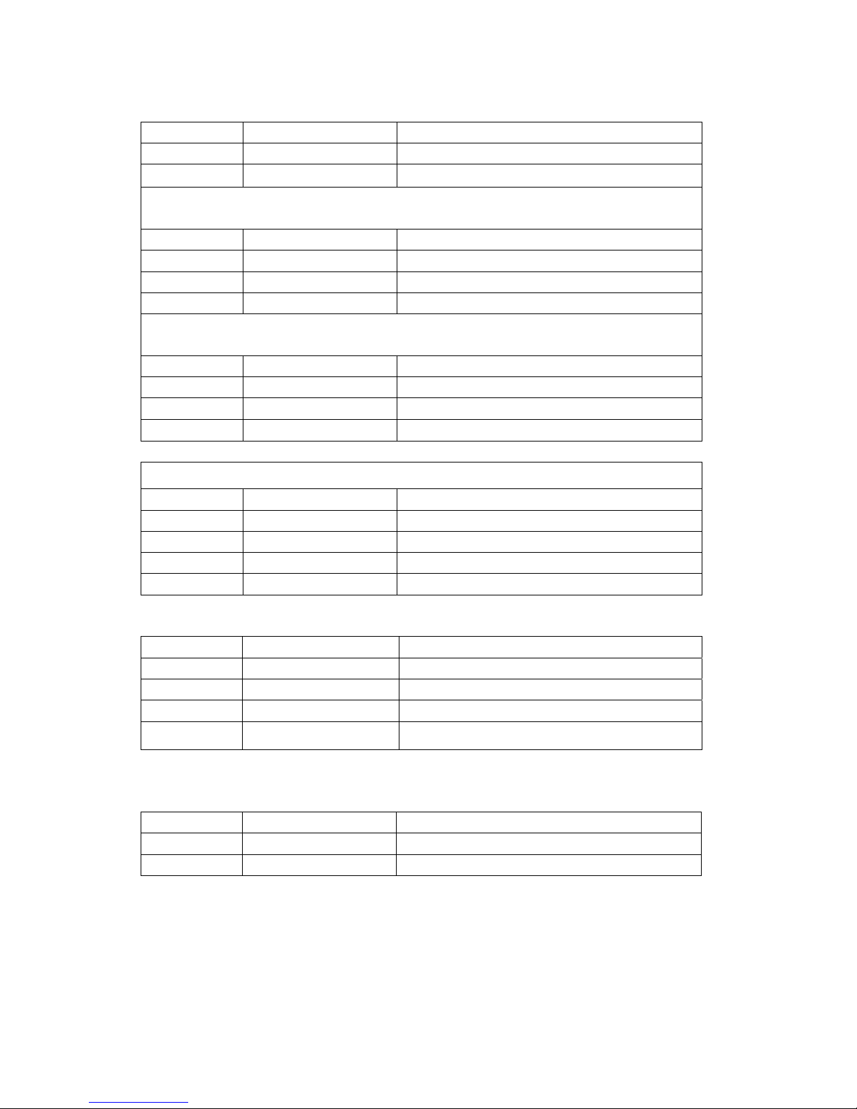
7. Menus in the fixture.
Root Menu Sub Menu 1 Sub Menu 2
STAT (STATIC LOOK) R(ED) 0-255
G(REEN) 0-255
B(LUE) 0-255
W(HITE) 0-255
S(STROBE) 0-255
AUTO (AUTOMATIC) AT 01 THROUGH TO AT10
DMX ASSIGN DMX CHANNEL 1-512
PERS (PERSONALITY) STAG(E)
ARC1
ARC1d
ARC2
AR2d
AR2s
HSV
ID ID 01 THROUGH 66
SET REST (RESET)
DIM DIM=0 to DIM=4
CURE CUR0 to CUR3
BSW ON/OFF
IDSW ON/OFF
POWS ON/OFF
CAL1 RGBW
KEY OFF
ON
TEMP In Centigrade
PWMF 1.2K – 24.0K

8. Static Look.
The Elektralite 1018 can be set to a single static look quickly.
Use the Menu button to get to STAT.
Press Enter.
The next screen will read R000. This is addressing the RED leds.
If Red is to be in the static look, then use the ↑or ↓to increase the value of the red.
Numbers are expressed in DMX values so 0 is no output and 255 is highest output.
Press Enter to save the value.
The screen will automatically advance to the next color Green.
If Green is to be in the static look, then use the ↑or↓to crease the value of green.
Press Enter to save the value.
The screen will automatically advance to the next color Blue.
If Blue is to be in the static look, then use the ↑or↓to crease the value of blue.
Press Enter to save the value.
The screen will automatically advance to the next color White.
If White is to be in the static look, then use the ↑or↓to crease the value of white.
Press Enter to save the value.
The screen will automatically advance to the strobe function.
If the strobe function is to be in the static look, then use the ↑or↓to crease the value of strobes flash
rate.
Press Enter to save the value.
This is the last entry and the static look is complete. Pressing the Enter key just continues around if
you need to make fine adjustments to the color of the static look.
Do not press MENU as this will get you out to the Root directory and out of the static look.

9. Auto Programs.
The Elektralite 1018 can be set to run some inbuilt programs.
There are ten programs in the Elektralite 1018.
They are labeled AT 01 to AT10.
10. DMX 512 Setting (address).
Sets up the address for the dmx.
Using the Menu button in the root menu go to DMX
Press Enter to get into DMX and the display will read the current dmx channel.
The display will read for example d.001
This means the fixture's current address is 1
To change it, use the ↑or ↓buttons to get to the correct address.
11. Fixture Personality.
There are several different choices on how the fixture will operate.
What these "Personalities" do in terms of their channel assignments is detailed in the tables on page
12.
To change a Personality use the Menu button to get to PERS
Press Enter then using the ↑or ↓buttons go to the personality required.
Press Enter to save the Personality.
The one Personality not defined in these tables is STAG. STAG is short for STAGE and it is the full
dmx number of channels as detailed in the DMX Channel Assignments shown on pages 13 & 14.
The full dmx number of channels is 11.
12. ID Address.
An Elektralite 1018 can be addressed (controlled) through the dmx or instead it can have its own
unique ID address.
There are a total of 66 different ID addresses from 1 to 66.
To set up the address for a fixture, use the Menu button in the root menu go to ID
Press Enter and then using the ↑or ↓buttons,to select the ID address.
Press Enter to save the address.
For the ID address to work you must chose a Personality that uses the ID. For example STAG
This allows you to access the ID address system on channel 11.
Set the DMX address to d.001 for the fixture. So if ID address 22 is chosen then go to channel11 on
the lighting board and set the level at 211. You will then be controlling only fixture(s) with ID address
22.

13. Set. (Set has several Sub Menus which allow functions to be used).
1). REST
This resets all values to their default.
Go through the Root Menu until Set. Press Enter and then use the ↑or ↓buttons to get to REST.
Press Enter. The display will have 4 dots across the bottom. The password needs to be entered.
The password is the following sequence using the ↑and ↓buttons.
↑↓↑↓press Enter once complete. The display will read OK followed by a return to the
REST sub menu. The Menu button will need pressing to return to the Root Menu. Only once at the
Root Menu will the dmx control function. Please note the Reset also takes the dmx address back to
001.
2). DIM
The Dim function allows different Dimmer curves to be chosen. There are 5 choices.
Choice 1 :- this is Dim off. The Dimmer curve is 0 which means any change in dimmer level is
instantaneous.
Choice 2:- Dim 1. The dimmer curve has the shortest fade in and fade out time.
Choice 3:- Dim 2. The dimmer curve has the 2nd shortest fade in and fade out time.
Choice 4:- Dim 3. The dimmer curve has the 3rd shortest fade in and fade out time
Choice 5:- Dim 4. The dimmer curve has the longest fade in and the fade out time.
To access the DIM function go through the Root Menu until SET is found. Press Enter and then use
the ↑or ↓buttons to get to DIM. Press Enter and then use the ↑or ↓buttons to get to DIM choice :
DIM0, DIM1, DIM2, DIM3 or DIM4. Once chosen, press Enter to save it and then use the Menu
button to exit back to the root directory.
Please note the DIM function under the Set menu in the fixture does not work when in the STAG
mode.
When is STAG mode you can operate/access the DIM function directly through channel 10 on your
lighting controller.
3). CURE
This mode sets up a dimmer curve.
CUREO is no curve at all. CURE1 through to CUR3 are different curve generators with CURE3
being more logarithmic and faster “attack” than CURE1. (The display only has 4 characters so the
labels are CUR0, CUR1, CUR2 and CUR3).
Using the Menu button, go through the Root Menu until Set. Press Enter and then use the ↑or ↓
buttons to get to CURE.
Press Enter and then use the ↑or ↓buttons to get to the CUR choice required. Once chosen, press
Enter to save it and then use the Menu button to exit back to the root directory.
4). BSW
In order to work mode CAL1, BSW must be turned on. Using the Menu button, go through the Root
Menu until Set. Press Enter and then use the ↑or ↓buttons to get to BSW. Press Enter and then
chose ON if you want to change the Elektralite 1018 white calibration under CAL1

13. Set (Cont). (Set has several Sub Menus which allow functions to be used).
5). ID SW
This mode turns On or OFF the ID address system. See section 12 above for an explanation of ID
address.
Using the Menu button, go through the Root Menu until Set. Press Enter and then use the ↑or ↓
buttons to get to IDSW.
Press Enter and then use the ↑or ↓buttons to choose On or Off. Once chosen, press Enter to save
it and then use the Menu button to exit back to the root directory.
6). POWS
This function is either ON or OFF
OFF : in this mode, when the temperature rises, the fan will come on and operate. The operation
time and speed of the fan is governed by the temperature. So if the leds are at 100% the fan will
operate to cool down the temperature and once that is achieved the fan will turn off. It will come back
on again as the temperature increases again.
ON : in this mode, when the temperature increases the fan will turn on but at the same time as the
fan is cooling the leds the leds will automatically reduce their output (and hence temperature) by up
to 10%.
Using the Menu button, go through the Root Menu until Set. Press Enter and then use the ↑or ↓
buttons to get to POWS.
Press Enter and then use the ↑or ↓buttons to choose On or Off. Once chosen, press Enter to save
it and then use the Menu button to exit back to the root directory.

14. CAL 1
CAL1 will allow you to set up the white balance for the RGBW components.
To adjust the white balance, go through the Root Menu until CAL1., the screen will display R255,
use the ↑or ↓to set the Red component to the value required. Press Enter to save and the screen
will automatically advance to the value for G (G255 for example). Again, use the ↑or ↓to make the
adjustment you require for the Green leds. Repeat for the blue leds and finally the white leds.
Press Menu to exit and get back to the Root Menu.
Now whenever the white is output using the Red, Green, Blue and White leds, the maximum values
are what is recorded in CAL1.
15. KEY
The Key function is an access password for the fixture. The KEY can be turned OFF or ON which
then deactivates or activates the password.
To set the KEY go through the Root Menu until KEY. Press Enter and use the ↑or ↓to set the KEY
to either OFF or ON. If the Key is turned ON then a password is required to go into sensitive Menus
and to change functions.
The password is ↑↓↑↓(Up + Down + Up + Down).
16. TEMP
This display gives the current temperature of the fixture. The temperature is in Centigrade.
17. PWMF
The speed at which the power supply operates at can be varied from 1.2 Khz to 24 Khz.
Slower frequency gives better dimming results while higher frequencies are needed for 4K video.
18. Glass front plate.
.
Certain fixtures come with a glass plate. This glass plate fits onto the front of the leds. It slots in the
gel frame holder and the clip latches the plate into position.
19. Personality tables.
(for the personality STAG please refer to the DMX channel assignments on pages 13 & 14.
STAG uses all 11 channels as shown in the dmx channel assignment table).
ARC1
1 0-255 RED
2 0-255 GREEN
3 0-255 BLUE
ARC1 D
1 0-255 MASTER
2 0-255 RED
3 0-255 GREEN
4 0-255 BLUE
ARC2
1 0-255 RED
2 0-255 GREEN
3 0-255 BLUE
4 0-255 WHITE
ARC2 D
1 0-255 MASTER DIMMER
2 0-255 RED
3 0-255 GREEN
4 0-255 BLUE
5 0-255 WHITE
ARC2 S
1 0-255 RED
2 0-255 GREEN
3 0-255 BLUE
4 0-255 WHITE
5 0-255 STROBE
HSV
1 0-255 H hue
2 0-255 S saturation level
3 0-255 V brightness

DMX Channel Assignments. (STAG)
1 Grand Master for RGBW 0-255
2 RED Leds 0-255
3 GREEN Leds 0-255
4 Blue Leds 0-255
5 White Leds 0-255
6 No effect 0-010
Crossfade Red255 Green 000→255 011-030
Crossfade Red 255→000 Green 255 Blue 000 031-050
Crossfade Red 000 Green 255 Blue 000→255 051-070
Crossfade Red000 Green 255→000 Blue 255 071-090
Crossfade Red 000→255 Green 000 Blue 255 091-110
Crossfade Red255 Green 000 Blue 255→000 111-130
Crossfade Red255 Green 000→255 Blue 000→255 131-150
Crossfade Red 255→000 Green 255→000 Blue 255 151-170
Snap to Red 255 Green 255 Blue 255 171-200
Color temperature 1 201-205
Color temperature 2 206-210
Color temperature 3 211-215
Color temperature 4 216-220
Color temperature 5 221-225
Color temperature 6 226-230
Color temperature 7 231-235
Color temperature 8 236-240
Color temperature 9 241-245
Color temperature 10 246-250
Color temperature 11 251-255
7 No effect/function 000-013
Strobe from 1Hz to 20 HZ 014-255
8 No Function 000-020
AT 01 (Automatic program 01) 021-030
AT 02 (Automatic program 02) 031-040
AT 03 (Automatic program 03) 041-050
AT 04 (Automatic program 04) 051-060
AT 05 (Automatic program 05) 061-070
AT 06 (Automatic program 06) 071-080
AT 07 (Automatic program 07) 081-090
AT 08 (Automatic program 08) 091-100
AT 09 (Automatic program 09) 101-110
AT 10 (Automatic program 10) 111-120
Sound active mode 121-255

DMX Channel Assignments (Cont.)
9 Run speed for AT01-AT10 on channel 08 000-255
10 System default setting 000-009
Dim 00 (straight line dimmer) 009-055
Dim 01 (dimmer curve 1. Shortest fade time) 056-105
Dim 02 (dimmer curve 2. 2nd Shortest fade time) 106-155
Dim 03 (dimmer curve 3. 3rd Shortest fade time) 156-205
Dim 04 (dimmer curve 4. Longest fade time) 206-255
11 All fixtures are addressed together 000-009
ID 01 010-019
ID 02 020-029
ID 03 030-039
ID 04 040-049
ID 05 050-059
ID 06 060-069
ID 07 070-079
ID 08 080-089
ID 09 090-099
ID 10 100-109
ID 11 110-119
ID 12 120-129
ID 13 130-139
ID 14 140-149
ID 15 150-159
ID 16 160-169
ID 17 170-179
ID 18 180-189
ID 19 190-199
ID 20 200-209
ID 21 210
ID 22 211
ID 23 212
ID 24 213
ID 25 214
ID 26 215
ID 27 216
ID 28 217
ID 29 218
ID 30 219
ID 31 220
ID 32 221
ID 33 222
The above continues to ID66 at DMX 255

20. Cleaning and maintenance.
Now ignoring maintenance and cleaning is very good way of creating problems "down the road" and
many companies and installations do just that. However the net result is, no matter what the fixture,
premature failure!
Changing the oil in a car most people do on a regular basis.
So with the fixtures regular maintenance it an excellent practice, if you want the fixtures to last.
So what is the maintenance for the fixture?
Clean the fan! That’s really it!
Turn off the Elektralite 1018.
Using a small vacuum cleaner, suck the dust and “fur balls” out.
Do not use a can of co². That will just blast the dust and dirt everywhere!
The fan keeps the LEDs cool and keep the electronics cool too.
Without the fan working efficiently and dust free, the fixtures will fail and that will be a lot more costly
than having someone vacuum the fixtures on a regular basis.
How often should the fan be cleaned? It depends on where the fixtures are; in a very dusty
atmosphere once a week. So check the fan on a regular basis, it may not need cleaned every week
but a quick “visual inspection” should be done.
The clear front plastic cover for the lenses should be cleaned so the light output is maintained. With
the Elektralite 1018 turned off, use only a moist lint-free cloth, and clean the plastic cover. Never use
alcohol or solvents to clean the fixture. Never spray anything onto the fixture at the front or in any
place on the fixture.
21. Technical Specification.
Operating voltage 100 – 250v
Frequency 50 – 60 Hertz
18 x quad leds
Fan cooled
305mm x 276mm x 230mm
12" x 10.9" x 9.1"
8.5 kgs
19 pounds
Elektralite is a division of Group One. Group One and its divisions are constantly improving
their product range and we reserve the right to make changes without prior notice.

Other Products.
For other great products that are manufactured under the Elektralite product line,
please go to the website at www.myelektralite.com
A preview of the products include:-
Elektralite Elektrabar with glare shield for perfect cuts
Utilizing homogenized 6-in-1 leds. RGBWAI where the I is indigo (not UV) ; this way perfect pastels
like Lee 170 Lavender are flawlessly achieved.
Elektralite ML902
The ML902 utilizes a 120 watt Led and is brighter than a 250 discharge light source.
Features include:- Color wheel, two gobo wheels, rotating gobos, rotating 3 facet prism, focus,
dimmer, strobe and 16 bit pan and tilt.

Elektralite Stingray Ellipsoidal
The Elektralite Stingray is a 300 watt LED ellipsoidal with the output of
a conventional 750 watt fixture. Different LED types are available including Warm White,
5600K, and RGBL
Elektralite SLA
The SLA is the perfect compact IP65 fixture for accent lighting everything from
trees and walls to product high lighting. Even though it is compact it packs a massive
punch with its 15 watt Cree RGBW leds.

Elektralite Dazer Downlight
The ideal pendant light. Made specifically for the installation market.
Can be simply installed by an electrical contractor. 180 watts of power.
Comes with 25degree lenses installed but a lens pack (15,45, & 60)
allows the beam angles to be changed.
Other manuals for 1018
1
Table of contents
Other elektraLite Dj Equipment manuals

elektraLite
elektraLite eyeBall IP65 User manual

elektraLite
elektraLite Stingray User manual

elektraLite
elektraLite CP10XT Operator's manual
 User manual")
elektraLite
elektraLite eyeBall (5-in-1) User manual

elektraLite
elektraLite Cool White Dazer User manual

elektraLite
elektraLite Dazer Downlight Warm White User manual

elektraLite
elektraLite LXE 700 Spot User manual


