Elektro-Automatik Rittal TS 47U User manual

Installationsanleitung
Installation Guide
Schrank
Cabinet
PSB Rack 47U: 09 114 664


3
EN
Installationsanleitung / Installation guide
09114664
DE
Technische Daten
• Typ: Rittal TS 47U
• Abmessungen (BxHxT): 1800 x ca. 2350 x 1000 mm
• Ausführung: mit Türen, auf Rollen
• AC-Anschluß: L1+L2+L3+PE
• AC-Versorgung: 380 V / 400 V / 480 V (L-L)
• AC-Strom bei 34 installierten Geräten: max. 952 A (2x
336 A, 1x 280 A)
• Gewicht: ca. 1860 kg (voll bestückt)
• DC-Bus: 1500 V / 1020 A / 510 kW
Standardkonguration
• Rollen (12 Stück, davon 6 dreh- und feststellbar)
• Bestückbar mit bis zu 36 Einheiten von Modell
» PSB 91500-30 bzw. PSB 91500-30 SLAVE
• Standardkonguration (34 Einheiten):
» Schrank 1: 2x PSB 9000, 10 x PSB 9000 SLAVE
» Schrank 2: 2x PSB 9000, 10 x PSB 9000 SLAVE
» Schrank 3: 2x PSB 9000, 8 x PSB 9000 SLAVE
Vorbereitung zur Installation
Wichtige Hinweise
• Verändern Sie nicht die interne Netzeingangs-
Verdrahtung bezüglich Leitungslänge, Absicherung
und Querschnitt!
• Der Netzanschluß muß extern abgesichert werden!
Aufstellung
Das System wird in Form von drei Schränken mit je
vier Rollen geliefert, von denen die zwei vorderen xiert
werden können und sollen. Nach jeder Ortsveränderung
sind diese wieder festzustellen.
Wichtige Hinweise
• Die Schränke dürfen nur auf horizontalen Flächen
aufgestellt und betrieben werden.
• Die Schränke müssen gegen Wegrollen gesichert
sein, neben der Fixierung der vorderen Rollen
notfalls durch weitere Maßnahmen
• Die Schränke sollten möglichst dicht nebeneinan-
der stehen. Die Aufstellung in einem Winkel von
90° zueinander ist nicht zulässig, weil sich dann
die Rückseiten von 2 Schränken gegenüberstehen
würden (Thema: Entlüftung)
Das System hat ein beträchtliches Gewicht. Stellen Sie
stets sicher, daß der Aufstellungsort und der Transport-
weg das Gewicht des System bzw. eines einzelnen
Schrankes plus mehrerer Personen mühelos tragen
können.
Technical specications
• Type: Rittal TS 47U
• Dimensions (WxHxD): 1800 x approx. 2350 x 1000 mm
• Model: with rear and front doors, on casters
• AC connection: L1+L2+L3+PE
• AC voltage: 380 V / 400 V / 480 V (L-L)
• AC current, with 34 units installed: max. 952 A (2x 336
A, 1x 280 A)
• Weight: approx. 1860 kg (fully equipped)
• DC bus: 1500 V / 1020 A / 510 kW
Default conguration
• Casters (12 pieces, 6 can be locked)
• Equippable with up to 36 units of model
» PSB 91500-30 or PSB 91500-30 SLAVE
• Default conguration (34 units):
» Rack 1: 2x PSB 9000, 10x PSB 9000 SLAVE
» Rack 2: 2x PSB 9000, 10x PSB 9000 SLAVE
» Rack 3: 2x PSB 9000, 8x PSB 9000 SLAVE
Preparing the installation
Important notes
• Do not modify the internal wiring, especially not
regarding cross section and cable length!
• The AC supply has to be fused externally!
Positioning
The system is delivered in form of three cabinets, each
with four casters of which two can be locked. After every
change of location they have to be locked again.
Important notes
• The cabinets must only be positioned and operated
on horizontal ground
• The cabinets must be secured against rolling o,
either by locking the casters or removing them
• The cabinets should be placed next to each other
and as close as possible. Arrangement with an
angle of 90° to each other is not allowed, because
then the rear side of two of the cabinets would face
each other (reason: ventilation)
The system has a considerable weight. Always make sure
that the ground it is positioned on can carry the system’s
weight, or that of a single unit, plus the weight of a few
persons without diculty.

4
EN
Installationsanleitung / Installation guide
09114664
DE
Be- und Entlüftung
Die Belüftung erfolgt über die Vorderseite (Zuluft) und
Rückseite (Abluft) der Schränke. Die Türen sind luftdurch-
lässig. Hinter dem Schrank muß daher mindestens 50 cm
Platz gelassen werden.
Vorderseite und Rückseite dürfen nicht durch irgendwel-
che Gegenstände abgedeckt sein, die eine Luftzufuhr
verhindern könnten.
Installation der Geräte
Die Geräte werden getrennt vom Schrank geliefert und
sollte im Zuge der Installation des Schrankes mitinstalliert
werden.
Der Lieferumfang des Schrankes bzw. der Geräte enthält
alle Montagematerialen und Leitungen, welche für die
Befestigung der Geräte im Schrank, deren elektrische
Verbindung untereinander, sowie die Verbindung der
drei Schränke benötigt werden. Bitte prüfen Sie nach
Erhalt der Lieferung den Lieferumfang des Systems auf
folgende Teile:
• DC-Abdeckungen:
» Sechskantbolzen 75 mm
» Abdeckungen (Plexiglas)
» Rändelmuttern M3
• Je Gerät:
» 4x Kreuzschlitzschraube M5 zur Befestigung der
Geräte im Schrank (Front)
» 2x Schraubenset M6 (befestigt an der DC-Klemme)
zur Verbindung mit DC-Bus
• DC-Bus:
» 6x Kupferschiene (40x10x1905 mm)
» 6x DC-Kabel (rot markiert), 2,5 m
» 6x DC-Kabel (blau markiert), 2,5 m
• Master-Slave-Bus (MS) & Share-Bus
» 31x Netzwerkkabel, 50 cm, für MS (Gerät zu Gerät)
» 2x Netzwerkkabel, 5 m, für MS (Schrank zu Schrank)
» 31x Share-Bus-Kabel, 20 cm, 4-polig, mit 2 Steckern
» 2x Share-Bus-Kabel, 5 m, 4-polig, mit 2 Steckern
» 1x Share-Bus-Verstärker „SBA 9000 Master“
» 33x Share-Bus-Verstärker „SBA 9000 Slave“
Zwecks besserer Zugänglichkeit sollten die Geräte vor
der Installation der Schränke und deren AC-Anschluß
eingebaut werden. Folgende Schritte:
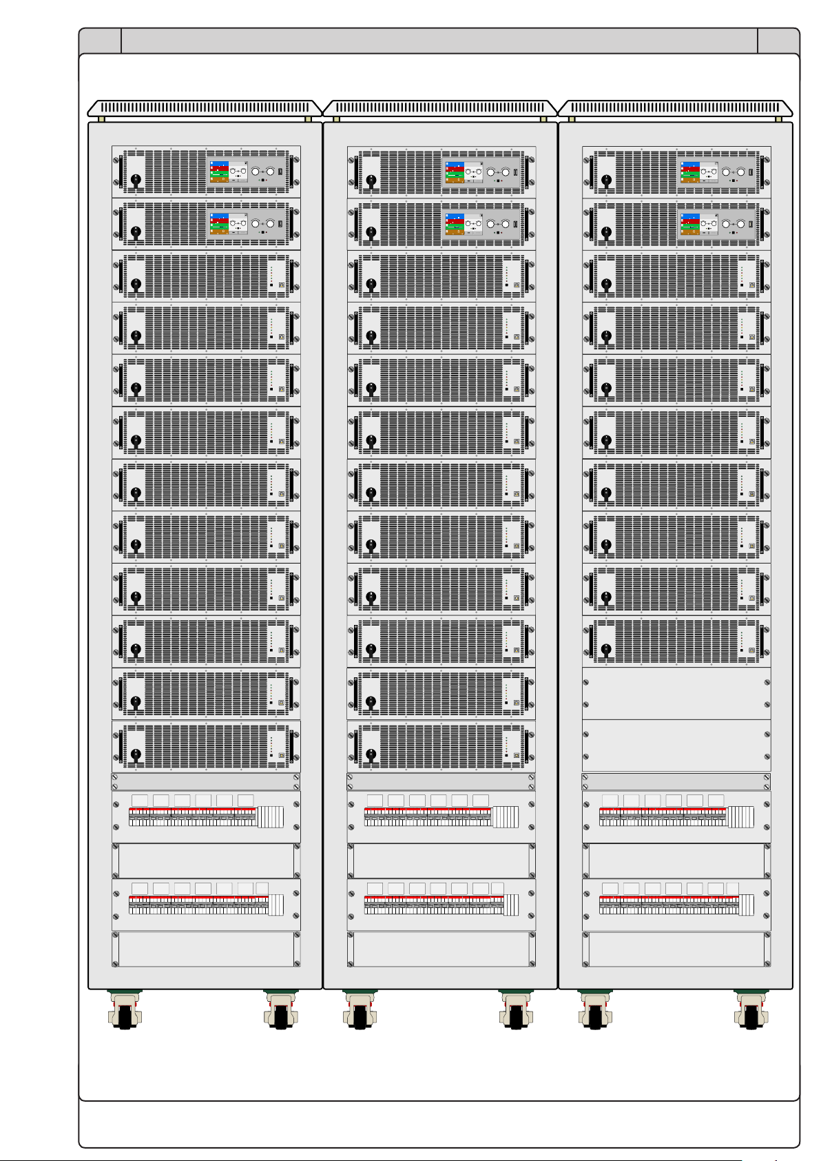
1. Geräte im Schrank plazieren
Schieben Sie die Geräte nacheinander in die vorgese-
henen Positionen (siehe auch Bild 1 weiter unten). Die
Schränke und Geräte sind gekennzeichnet, so daß eine
Zuordnung erleichtert wird. Z. B. ist „Rack 1“ der erste
Schrank (links oder rechts positioniert“ und „Unit 1“ ist
das 1. und oberste Geräte im Rack 1.
Es gilt hierbei: Unit 1 in Rack 1 ist der Master des
Systems. Er ist zudem extra gekennzeichnet.
Air cooling
Operating the cabinets requires unobstructed air ventila-
tion from the front to the back. The installed doors have
a mesh which allows for sucient air circulation. Behind
the cabinets it requires to have at least 50 cm of space
for exhausting air.
Front and back door must not be obstructed in any way.
Device installation
The devices are delivered separate from the cabinets
and should be installed in the cabinet after they have
been installed in upright position in their target location.
The scope of delivery of the cabinet includes all material
and cable required for the installation of the devices and
the electrical connection to each other and also between
the cabinets.
After unpacking the cabinets verify the scope of delivery
for following content:
• DC covers
» Hexagon bolts 75 mm
» Cover pieces (acrylic glass)
» Knurled nuts (M3)
• Per unit:
» 4x Cross-head screw M5 to x the unit inside the
cabinet on the front
» 2x Screw set M6 (tied to the DC terminal), to connect
the unit to the DC bus
• DC bus:
» 6x DC bus bar (copper, 40x10x1905 mm)
» 6x DC cable (marked red), 2.5 m
» 6x DC cable (marked blue), 2.5 m
• Master-slave (MS) bus & Share bus:
» 31x network cable, 50 cm, for MS (unit to unit)
» 2x network cable, 5 m, for MS (cabinet to cabinet)
» 31x Share bus cable, 20 cm, 4-wire, with 2 plugs
» 2x Share bus cable, 5 m, 4-wire, with 2 plugs
» 1x Share bus amplier “SBA 9000 Master”
» 33x Share bus amplier “SBA 9000 Slave”
Due to better accessibility, it is recommended to install
the devices before connecting the cabinets to AC supply.
1. Placing the devices in the cabinet
Insert the units from top to bottom into the dedicated po-
sitions (also see Figure 1 drawing below). The cabinets
and devices are labeled to simplify the assignment and
installation. For example, “Rack 1” is the rst cabinet
(placed on the left or right) and “Unit 1” is the rst and
topmost unit in Rack 1.
Rule: Unit 1 in Rack 1 is the system master. It is also
labeled as such.

5
EN
Installationsanleitung / Installation guide
09114664
DE
Es ist vorgesehen, daß jeder Schrank zwei Einheiten
mit Anzeige und Touchpanel enthält, wobei eine von den
sechs Einheiten mit Anzeige der Master („Master“) des
gesamten Systems ist. Dieser Master muß sich in einem
der äußeren Schränke benden, damit die vorgesehene
Share-Bus-Verdrahtung eingehalten werden kann. Somit
sollte Rack 1 entweder rechts oder links vom mittleren
Schrank plaziert werden.
Diese Master-Einheit hat dafür auch den einzigen Share-
Bus-Verstärker für Master (SBA 9000 Master) montiert.
Das kann ggf. auch vom Druck des auf der Rückseite der
Gerät montierten Moduls abgelesen werden.
Nach dem Einschieben eines Gerätes muß dessen
Frontplatte auf den seitlichen, vertikalen Lochstreifen im
Schrank auiegen. Befestigen Sie das Gerät mittels der
Langlochbohrungen links und rechts von den Grien und
den vernickelten M5-Schrauben.
2. Kupferschienen montieren
Es ist vorgesehen, jeweils alle Geräte in einem Schrank
an deren DC-Anschlüssen zu verbinden. Dazu werden
pro Schrank 2 Kupferschienen mitgeliefert, die mit „+“ und
„-“ gekennzeichnet sind. Diese werden mittels der M6-
Schraubensets (siehe DC-Anschluß der Geräte) seitlich
außen an den DC-Anschlüssen der Geräte befestigt.
Siehe dazu auch Bild 2 weiter unten. Die Schraubensets
benden sich an den Geräten. Die mit „-“ gekennzeichne-
ten Schienen sind für den Minuspol vorgesehen, welcher
sich auf der linken Seite des DC-Anschlusses bendet,
von der Rückseite des Schrankes aus gesehen.
Es wird empfohlen, pro Gruppe erst alle Schraubensets
durch die Bohrungen zu führen und die Muttern locker
aufzuschrauben, bevor alle fest angezogen werden.
3. DC-Bus zwischen den Schränken
In der Standardkonguration des Systems ist es vorgese-
hen, alle drei Schränke DC-seitig zu verbinden, wobei der
eigentliche DC-Hauptanschluß für externe Quellen oder
Lasten im mittleren der drei Schränke zu denieren ist.
Um die Schränke untereinander verbinden zu können,
werden rot (positiver Anschlußpol) und blau (negativer
Anschlußpol) markierte, 2,5 m lange Kabel mitgeliefert.
Diese sind mit M12-Ringkabelschuhen versehen und
werden daher am unteren Ende der DC-Bus-Schienen
an den Bohrungen für M12-Schrauben befestigt. Siehe
auch die Zeichnung Bild 5 unten.
4. DC-Kabel für externe Lasten/Quellen anschließen
Das ganze System kann bis zu 36 Geräte des Modells
PSB 91500-30 (Standard- oder Slave-Version) aufneh-
men. Die Geräte sind bidirektional. Das bedeutet, der
DC-Anschluß ist gleichzeitig ein DC-Eingang für externe
Spannungsquellen (Senke-Betrieb) und DC-Ausgang
für externe Lasten (Quelle-Betrieb). Besonders wenn
externen Spannungsquellen angeschlossen wurden, sind
besondere Vorsichtsmaßnahmen geboten.
It’s intended to have two units with display and touch
panel in every cabinet, of which one is dened as master
for the entire system, labeled “Master”. This unit must be
positioned in one of the outer cabinets and be the top-
most unit, in order to achieve the Share bus connection
as planned.
This master unit is also the one holding the only included
Share bus amplier for masters (“SBA 9000 Master”, can
also be read from the amplier module prit), mounted on
the rear plate of the device.
After inserting an unit its front plate must rest on the ver-
tical hole-punched mount strips on the sides. Then the
unit is xed using the long hole drillings next to the grips
and the nickel plated M5 screws (4x per unit).
2. Mounting the DC bus bars
It is intended to connect all units in every cabinet on
their DC terminals using two of the included copper bars.
These are supposed to be attached on the sides of the
DC terminal. Also see Figure 2 further below.
The M6 screw sets, as attached to the devices’ DC ter-
minals, are used to tighten the bars. The bars labeled
“-” are for the negative DC pole, which is on the left side
of the DC terminal, when seen from behind the cabinet.
It’s recommended to rst put all screw sets (screw, wash-
ers, lock washer, nut) through the holes and loosely screw
the nut, then tighten all nuts rmly.
3. Connect the DC bus between the cabinets
In the default conguration of the system it’s intended
to connect all three cabinet on their DC buses, where
the central cabinet is supposed to have the actual DC
connection point for external loads and sources.
In order to connect the cabinet to each other there are
2.5 m DC cables included, marked red (for positive pole)
or blue (for negative pole). They have M12 ring lugs and
are screwed to the lower end of each DC bus, using
the drillings for M12 screws (3x on each bar). Also see
drawing Figure 5 below.
4. Connect cables for external loads/sources
The entire system can hold up to 36 units of PSB 91500-
30 models (standard or slave version). These devices are
bidirectional. It means, the DC bus is an input for external
sources (sink operation) and an output for external loads
(source operation) at the same time. Especially when
connecting external sources to the cabinet, higher safety
measures have to be considered in order to protect per-
sons working on the DC bus from harm.
6
EN
Installationsanleitung / Installation guide
09114664
DE
Die Spannung der externen Quelle kann noch anlie-
gen und am Schrank arbeitenden Personen gefährlich
werden, selbst wenn der Schrank ansonsten komplett
ausgeschaltet und vom Netz getrennt worden ist.
Die Leitungen zu externen Lasten oder Quellen sind
nicht im Lieferumfang des Schrankes oder der Geräte
enthalten und müssen vom Anwender der Anwendung
und den Anforderungen gängiger Normen entsprechend
selbst gefertigt werden.
Die Enden der externen Kabel müssen, unabhängig von
der Wahl des Querschnitts der Leitungen, immer mit
M8 oder M12 Ringkabelschuhen versehen sein. Diese
können an den 7 Anschlußpunkten am unteren Ende mit
angeschraubt werden.
Die Anzahl der zu verwendenden Kabel pro Anschlußpol
und deren Querschnitt hängt vom Strom des kongurier-
ten Master-Slave-Systems ab. Der Master kann 1-35
Slaves initialisieren, demnach kann der Gesamtstrom
des Systems von 60 A bis 1080 A sein. Es wird jedoch
empfohlen immer Leitungen zu verwenden, deren ge-
samter Querschnitt für den maximal möglichen Strom
ausgelegt ist.
Achtung!
Externe DC-Quellen immer polrichtig anschließen!
Die Geräte haben keinen Schutz gegen Verpolung und kön-
nen auch im ausgeschalteten Zustand beschädigt werden.
5. DC-Abdeckung montieren
Die mitgelieferten Sechskantbolzen dienen zur Befesti-
gung der DC-Abdeckungen (je eine pro Gerätegruppe),
die wiederum als Berührungsschutz dient. Es ist vorge-
sehen, die 75 mm Bolzen an an Einheiten 1, 5, 6, 9 und
10 (von oben gezählt) jedes Schrankes zu montieren.
Dazu ist jeweils oberhalb des DC-Anschlusses eine M3-
Gewindebohrung (siehe Bild 2, gelber Kreis). Dort sind die
75 mm Sechskantbolzen einzuschrauben. Auf diesen wird
dann die DC-Abdeckung mit einer Rändelmutter befestigt.
6. AC-Anschluß der Geräte
Der AC-Anschluß ist in Form eines Steckers für alle
Geräte im Schrank bereits vorhanden. Er muß lediglich
gesteckt werden. Danach wird der am AC-Filter montierte
Winkel xiert. Dieser soll den AC-Stecker gegen Heraus-
rutschen sichern. Das Netzkabel kann dann noch am
Winkel mittels einen Kabelbinders xiert werden. Siehe
auch die Zeichnung von der Rückansicht.
7. Master-Slave-Bus verbinden
Der Master-Slave-Bus wird innerhalb des Schrankes
von Gerät zu Gerät mittels der mitgelieferten 50 cm
Netzwerkkabeln bzw. auch zwischen den Schränken mit
5 m langen Netzwerkkabeln verbunden. Siehe dazu Bild
4 weiter unten.
Weitere Informationen zum Master-Slave-Bus, dessen
Einstellungen und Busabschluß, sowie den Betrieb sind
im Handbuch zu den Geräten auf dem mitgelieferten
USB-Stick zu nden.
Even if the cabinet is completely switched o and cut
from AC supply, there can be dangerous voltage present
from outside.
The cables to connect to external loads or external sourc-
es are not included in the delivery and must be manufac-
tured according to the requirements of the application,
local standards and safety provisions.
It’s required to crimp M8 or M12 ring lugs onto the cable
ends which are going to be mounted on the DC bus. There
are 7 connection points on the lower end of the bus, of
which 3x are for M12 and 4x are for M8 screws.
The number of cables per pole and their cross sections
depends on the current of the master-slave setup. The
master can initialize any number of slaves from 1 to 35,
so the total current of the system can vary from 60 A to
1080 A. However, for safety reasons it’s recommended
to use cables with a total cross section matching the
maximum current of the system.
Attention!
Always connect external DC sources with correct polarity!
The devices do not have protection against false polarity
and can even be damaged in switched-o state.
5. Mounting the DC cover
The included hex bolts serve to mount the acrylic glass
DC covers, which must be installed as a protection against
touching the bus bars with their dangerous voltage level.
The units have a threaded hole above the DC terminal
(see Figure 2, yellow circle). The 75 mm hexagon bolts
are intended to be installed on the units 1, 5, 6, 9 and 10
of every cabinet. After this the cover is placed onto the
hex bolts’ ends and xed with the knurled nuts.
6. Connecting AC supply to the devices
The AC input of the devices is simply connected with the
plugs installed in the cabinet. After this, the xture on the
AC lter box can be tied again, also xing the AC cable
with a cable strap.
Also see the rear view drawing of the cabinet below.
7. Connecting the master-slave bus
The master-slave bus is connected from device to device
within the cabinets, using the supplied 50 cm network
cables. For the connection between the cabinets there
5 m cables included. Also see Figure 4 below.
Further information about the master-slave bus, its
settings and bus termination, as well as master-slave
operation can be found in the user manual of the devices,
which is included on the supplied USB stick.
7
EN
Installationsanleitung / Installation guide
09114664
DE
8. Share-Bus verbinden
Der Share-Bus wird für den Parallelbetrieb der Geräte
innerhalb des Schrankes und auch des Systems genauso
benötigt wie der Master-Slave-Bus. Die benötigten Ka-
bel (4-polig) sind mitgeliefert und müssen nur gesteckt
werden.
Siehe auch „Bild 3 - Schema der Share-Bus-Verdrahtung
(von hinten gesehen)“ weiter unten.
Die Schränke bzw. das System nutzt aufgrund der hohen
Anzahl von Geräten zusätzliche Share-Bus-Verstärker,
die zwischen dem eigentlichen Share-Bus-Anschluß des
Gerätes (Rückseite, zweipolige Klemme „Share“) und
dem nächsten Gerät sitzen. Somit benden sich immer
zwei Verstärker zwischen zwei Geräten. Der Master-Ver-
stärker ist die treibende Einheit und darf daher in diesem
System, das grundlegend aus 2-36 Einheiten bestehen
kann, nur einmal vorhanden sein, zumindest nur einmal
in einer der am Share-Bus verbundenen Einheiten. Der
Master-Verstärker ist auch das Modul, an dem die 24 V
Versorgungsspannung angesteckt wird, welche dann
über die 4-poligen Kabel von Verstärkermodul zu Verstär-
kermodul durchgeschlien wird. Die Versorgungsspan-
nung ist mit einer zweipoligen Leitung im Schrank nach
oben gelegt, wodurch sich ergibt, daß das Master-Gerät
immer ganz oben im Schrank sein muß.
Installationsschritte:
a) Überprüfen, wo der „Master“ im System sitzt
Wenn man die drei Schränke von vorn betrachtet, muß
das Mastergerät entweder oben links oder oben rechts
positioniert sein. Zudem muß der Master das Gerät sein,
auf dessen Rückseite der Master-Verstärker („SBA 9000
Master“, siehe Aufdruck) montiert ist.
b) Stromversorgung Master-Verstärker
Auf der Rückseite der Schränke ist seitlich eine Versor-
gungsleitung für die Share-Bus-Verstärker nach oben
geführt. Diese endet neben dem obersten Gerät. Der
Master-Verstärker hat eine dreipolige Anschlußklemme,
wo Versorgungsleitung mit einem dreipoligen Stecker
aufgesteckt wird.
c) Share-Busleitungen zu den Slaves
Siehe dazu auch Bild 3 weiter unten. Jede Slave-Einheit,
ob mit Anzeige oder ohne, hat auf der Rückseite einen
Share-Bus-Verstärker „SBA 9000 Slave“ montiert. Begin-
nend beim Master werden die 4-poligen Steckbuchsen
von oben nach unten mit den kurzen 4-poligen Share-
Bus-Leitungen durchverbunden. Am untersten Gerät
angekommen, wird ein langes 4-poliges Kabel vom un-
tersten Gerät bis zum obersten des nächsten Schrankes
verbunden, danach wieder kurze 4-polige usw.
Hinweis
Falls die Geräte in den Schränken an ihren Netzdreh-
schaltern ausgeschaltet werden und das System anson-
sten AC-seitig versorgt wird, läuft die Hilfsversorgung
für die Share-Busverstärker noch. Die kann mittels
des eines zweipoligen Automaten (Vorderseite, F13)
ausgeschaltet werden.
8. Connecting the share bus
The Share bus is required for parallel operation as well.
The required cables (4-wire) are included in the delivery,
precongured and ready to be plugged. It has three plugs
for three units and is plugged to the two-pin connectors
on the rear side labelled as “Share”.
Also see „Figure 3 - Share bus wiring scheme (seen from
the rear)“ below.
Due to the high number of units in this system it requires to
use ampliers for the Share bus. These ampliers come in
form of small modules and are mounted on the rear plate
of the devices and are basically placed between the actual
Share bus socket (“Share”) and the next unit. It means
that between two units there are two amplier modules.
The master amplier is the driving unit and meant to re-
ceive the auxiliary supply voltage, which is laid inside the
cabinet and exits in the top position, so the master with its
master amplier is required to be placed in the topmost
position. There must only be one master amplier in one
chain of 2-36 units. The connection between the units is
then made using the included short (20 cm) or long (5 m)
4-wire Share bus cables.
Steps of installation:
a) Verify the master to be in correct position
When looking at the three cabinets from the front, the
master unit is supposed to be positioned in the top-left
or top-right slot. The master device is the unit where the
master amplier (“SBA 9000 Master”, see print on mod-
ule) is mounted on the rear.
b) Power supply for the master amplier
On the rear side of the cabinet there is a two-wire cable
leading up on the side and ending next to the topmost unit.
It holds a three-pole connector which is simply plugged in
the three-pole counterpart of the master amplier module.
c) Share bus connection to the Slaves
Also see Figure 3 below. Every slave device, no matter
with or without display/touch panel, has a Share bus slave
amplier (“SBA 9000 Slave”) mounted on the rear. They
all have two 4-pole connectors for the wiring to the slave
amplier of the next upper and next lower unit.
Beginning with the master, the Share bus slave ampliers
are connected from unit to unit using the 20 cm Share
bus cables until you come to the lowest unit. From there
it connects with the 5 m 4-pole Share bus cable to the
next cabinet and from there with the short cables going
down to the lowest unit etc.
Note
In case the units in the cabinets are switched o one by
one using their front power switches, the auxiliary for
the Share bus ampliers remains powered. It’s recom-
mended to switch this o as well, with front breaker F13.
8
EN
Installationsanleitung / Installation guide
09114664
DE
Den Schrank anschließen
AC-Versorgung
Für den AC-Anschluß an die Hauptversorgung ist in
jedem Schrank ein Anschlußklemmbock an der Rück-
seite (unten Mitte) zugänglich, der mit L1, L2, L3 und
PE beschriftet ist.
Hinweis
Der PE-Leiter ist unbedingt erforderlich und muß an-
geschlossen sein!
Die AC-Versorgung der PSB-Geräte ist mit je einem
32 A-Automaten abgesichert. Diese Automaten sind
auf der Vorderseite des Schrankes zugänglich. Die
Hilfsversorgung der Share-Bus-Verstärker ist mit einem
Doppel-16 A-Automaten abgesichert.
Die externe Verkabelung und Absicherung der AC-Ver-
sorgung muß gängigen Vorschriften und Anforderungen
entsprechen.
Anschlußklemme (pro Schrank):
• Empfohlener Kabelquerschnitt: 70 mm²
• Empfohlene externe Absicherung: 350 A
• Anzugsdrehmoment: 25 - 30 Nm
• Abisolierungslänge: 40 mm
Ethernet
Jeweils eins der Geräte mit Anzeige pro Schrank hat eine
Ethernetschnittstelle installiert. Diese kann beim Master
zum Steuern und überwachen des gesamten Systems
genutzt werden. Bei Slaves ist nur Überwachung möglich.
Fernfühlung
Fernfühlung ist eine optional nutzbare Funktion und daher
ist der Fernfühlungsanschluß „Sense“ (Rückseite der
Geräte) nicht zwangweise zu verbinden. Soll Fernfühlung
genutzt werden, muß sie im Fall eines Master-Slave-Sy-
stems jedoch am Master und nur dort verbunden werden.
Für dieses System aus drei Schränken gilt zudem eine
Besonderheit: die Signale auf der Fernfühlungsleitung
müssen geltert bzw. gedämpft werden. Das bedingt eine
zusätzliche Hardware, die in Form einer kleinen Box in
der Nähe des Mastergerätes angebracht ist. Siehe dazu
auch Bild 6 als Verdrahtungsschema.
Es gilt:
• Soll Fernfühlung genutzt werden, so muß die Box...
» am Eingang „Sense“ und
» am DC-Anschluß (DC-Busschiene) und
» an der externen Last bzw. Quelle angeschlossen sein.
• Soll Fernfühlung nicht genutzt werden, so muß...
» der Stecker am Eingang „Sense“ abgezogen und
» die Verbindung der Box zum DC-Bus getrennt werden.
Connecting the cabinet
AC supply
The AC connection is done using the terminal block in
each cabinet which is accessible on the rear side of the
cabinet in the bottom center and which is labeled with
L1, L2, L3 and PE.
Note
The PE conductor is absolutely required!
The AC supply for the PSB units is fused with a 32 A
circuit breaker each. These CBs are accessible on the
front side of the cabinet. The internal auxiliary supply of
the Share bus ampliers is fused with a double 16 A CB.
The AC wiring and external fusing has to meet local
specications and regulations.
AC screw terminal (for each cabinet):
• Recommended cable cross section: 70 mm²
• Recommended external fusing: 350 A
• Required torque: 25 - 30 Nm
• Stripping length: 40 mm
Ethernet
The master in the system is equipped with an Ethernet
interface which can be used to remotely control and
monitor the entire system if needed, while slaves can
only be monitored.
Remote sensing
Remote sensing is a standard feature which can be used
optionally and is thus the rear connector “Sense” isn’t nec-
essarily wired. In case remote sensing is going to be used
in this system, the Sense input of the master - and only
of the master - can be wired to the external load/source.
Due to the construction, the operation of remote sensing
requires special ltering an dampening, so there is special
handling required. The system requires an extra hardware
in form of a small box which is installed in cabinet which
hold the master (Rack 1) and next to master unit. See
gure Figure 6 as wiring reference.
Rules of thumb:
• If remote sensing is going to be used, the box must...
» be connected to input “Sense” and
» to the DC bus (copper bars) and
» to the external load/source.
• If remote sensing is not used or not anymore, you must..
» removed the plug from input “Sense” and
» disconnect the cable from the DC bus
9
EN
Installationsanleitung / Installation guide
09114664
DE
Betrieb
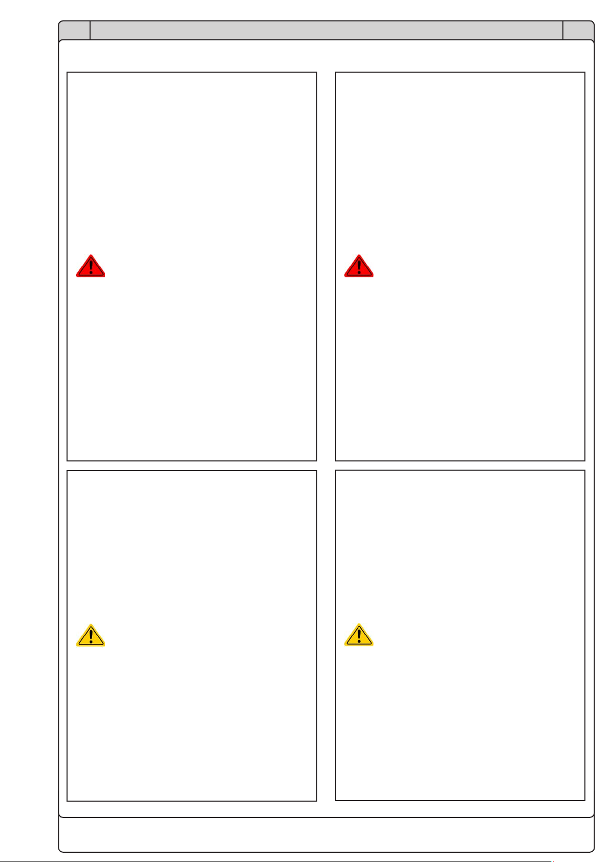
Achtung! Lebensgefahr!
• Beim Betrieb elektrischer Geräte
stehen zwangsweise bestimmte Teile
unter teils gefährlicher Spannung.
Daher sind alle spannungsführenden
Teile abzudecken!
• Alle Arbeiten an den Anschlußklemmen
müssen im spannungslosen Zustand
des Gerätes erfolgen (Eingang nicht
verbunden mit Spannungsquellen) und
dürfen nur von Personen durchgeführt
werden, die mit den Gefahren des
elektrischen Stroms vertraut sind oder
unterrichtet wurden! Unsachgemäßer
Umgang mit diesen Geräten kann zu
tödlichen Verletzungen, sowie erheb-
lichen Sachschäden führen.
• Berühren Sie die Kontakte am Netz-
kabel oder der Netzanschlußbuchse
nie direkt nach dem Entfernen des
Kabels aus der Steckdose oder dem
Hauptanschluß, da die Gefahr eines
Stromschlags besteht!
• Da einige Geräte im Schrank Senken
sind und einen Eingang haben, kann
an diesem selbst bei Trennung der
AC-Versorgung noch berührungsge-
fährliche Spannung von einer externen
Quelle anliegen!
• Das Gerät ist ausschließlich seiner Bestim-
mung gemäß zu verwenden!
• Das Gerät ist nur für den Betrieb innerhalb
der auf dem Typenschild angegebenen
Anschlußwerte und technischen Daten
zugelassen.
• Führen Sie keine mechanischen Teile,
insbesondere aus Metall, durch die Lüf-
tungsschlitze in das Gerät ein.
• Vermeiden Sie die Verwendung von Flüs-
sigkeiten aller Art in der Nähe des Gerätes,
diese könnten in das Gerät gelangen.
Schützen Sie das Gerät vor Nässe, Feuch-
tigkeit und Kondensation.
• Für Netzgeräte und Batterielader: Schlie-
ßen Sie Verbraucher, vor allem niederoh-
mige, nie bei eingeschaltetem Leistungs-
ausgang an, es können Funken und
dadurch Verbrennungen an den Händen,
sowie Beschädigungen am Gerät und am
Verbraucher entstehen!
• Keine externen Spannungsquellen mit um-
gekehrter Polarität am DC-Ausgang bzw.
DC-Eingang anschließen! Das Gerät wird
dadurch beschädigt.
Operation
Mortal danger - Hazardous
voltage
• Electrical equipment operation means
that some parts can be under danger-
ous voltage. Therefore all parts under
voltage must be covered!
• All work on connections must be car-
ried out under zero voltage (input not
connected to source) and may only be
performed by qualied and informed
persons. Improper actions can cause
fatal injury as well as serious material
damage.
• Never touch cables or connectors di-
rectly after disconnecting from mains
supply, as there is risk of electric shock
due to not yet fully discharged capac-
itors!
• Some of the devices in the cabinet are
sinks, which are supplied voltage from
external sources. Even in situations
where the cabinet is disconnected from
AC supply hazardous voltage could still
supplied to the DC bus by a source!
• The equipment must only be used as
intended
• The equipment is only approved for use
within the connection limits stated on the
product label.
• Do not insert any object, particularly metal-
lic, through the ventilator slots
• Avoid any use of liquids near the equip-
ment. Protect the device from wet, damp
and condensation.
• For power supplies and battery chargers:
do not connect users, particularly low re-
sistance, to devices under power; sparking
may occur which can cause burns as well
as damage to the equipment and to the
user.
• Do not connect DC power sources to
electronic load devices while the input is
switched on. Sparking may occur which
can cause burns as well as damage to the
equipment and to the source.
• ESD regulations must be applied when
plugging interface cards or modules into
the relative slot
10
EN
Installationsanleitung / Installation guide
09114664
DE
• Für elektronische Lasten: Schließen Sie
Spannungsquellen nie bei eingeschaltetem
Leistungseingang an, es können Funken
und dadurch Verbrennungen an den Hän-
den, sowie hohe Spannungsspitzen und
Beschädigungen am Gerät und an der
Quelle entstehen!
• Um Schnittstellenkarten oder -module in
dem dafür vorgesehenen Einschub (Slot)
zu bestücken, müssen die einschlägigen
ESD –Vorschriften beachtet werden.
• Nur im ausgeschalteten Zustand darf eine
Schnittstellenkarte bzw. -modul aus dem
Einschub herausgenommen oder bestückt
werden. Eine Önung des Gerätes ist nicht
erforderlich.
• Für elektronische Lasten: keine Span-
nungsquelle am DC-Eingang anschließen,
die eine Spannung erzeugen kann, die
höher ist als 110% der Nenneingangs-
spannung der Last. Das Gerät ist gegen
Überspannungen nicht geschützt, diese
können das Gerät zerstören.
• Niemals Netzwerkkabel, die mit dem Ether-
net oder dessen Komponenten verbunden
sind, in die Master-Slave-Buchsen auf der
Rückseite stecken!
Verantwortung des Bedieners
Das Gerät bendet sich im gewerblichen Einsatz. Das
Personal unterliegt daher den gesetzlichen Pichten zur
Arbeitssicherheit. Neben den Warn- und Sicherheitshin-
weisen in dieser Anleitung müssen die für den Einsatz-
bereich gültigen Sicherheits-, Unfallverhütungs- und Um-
weltschutzvorschriften eingehalten werden. Insbesondere
gilt, daß die das Gerät bedienenden Personen:
• sich über die geltenden Arbeitsschutzbestimmungen
informieren.
• die zugewiesenen Zuständigkeiten für die Bedienung,
Wartung und Reinigung des Gerätes ordnungsgemäß
wahrnehmen.
• vor Arbeitsbeginn die Betriebsanleitung vollständig
gelesen und verstanden haben.
• die vorgeschriebenen und empfohlenen Schutzausrü-
stungen anwenden.
• Weiterhin ist jeder an dem Gerät Beschäftigte in seinem
Zuständigkeitsumfang dafür verantwortlich, daß das
Gerät stets in technisch einwandfreiem Zustand ist.
Pichten des Betreibers
Betreiber ist jede natürliche oder juristische Person, die
das Gerät nutzt oder Dritten zur Anwendung überläßt und
während der Nutzung für die Sicherheit des Benutzers,
des Personals oder Dritter verantwortlich ist.
• Interface cards or modules may only be
attached or removed after the device is
switched o. It is not necessary to open
the device.
• Do not connect external power sources with
reversed polarity to DC input or outputs!
The equipment will be damaged.
• Do not connect a power source to the DC
input which can generate a voltage more
than 110% of the nominal input voltage of
the load. The equipment is not protected
against over voltage and may be irrepara-
bly damaged.
• Never insert a network cable which is con-
nected to Ethernet or its components into
the master-slave socket on the back side
of the device!
Responsibility of the user
The equipment is in industrial operation. Therefore the
operators are governed by the legal safety regulations.
Alongside the warning and safety notices in this manual
the relevant safety, accident prevention and environmen-
tal regulations must also be applied. In particular the users
of the equipment:
• must be informed of the relevant job safety require-
ments
• must work to the dened responsibilities for operation,
maintenance and cleaning of the equipment
• before starting work must have read and understood
the operating manual
• must use the designated and recommended safety
equipment.
• Furthermore, anyone working with the equipment is
responsible for ensuring that the device is at all times
technically t for use.
Responsibility of the operator
Operator is any natural or legal person who uses the
equipment or delegates the usage to a third party, and
is responsible during its usage for the safety of the user,
other personnel or third parties.
11
EN
Installationsanleitung / Installation guide
09114664
DE
Das Gerät wird im gewerblichen Bereich eingesetzt. Der
Betreiber des Gerätes unterliegt daher den gesetzlichen
Pichten zur Arbeitssicherheit. Neben den Warn- und
Sicherheitshinweisen in dieser Anleitung müssen die für
den Einsatzbereich des Gerätes gültigen Sicherheits-,
Unfallverhütungs- und Umweltschutzvorschriften einge-
halten werden. Insbesondere muß der Betreiber:
• sich über die geltenden Arbeitsschutzbestimmungen
informieren.
• durch eine Gefährdungsbeurteilung mögliche zusätz-
liche Gefahren ermitteln, die sich durch die speziellen
Anwendungsbedingungen am Einsatzort des Gerätes
ergeben.
• in Betriebsanweisungen die notwendigen Verhaltensan-
forderungen für den Betrieb des Gerätes am Einsatzort
umsetzen.
• während der gesamten Einsatzzeit des Gerätes re-
gelmäßig prüfen, ob die von ihm erstellten Betriebs-
anweisungen dem aktuellen Stand der Regelwerke
entsprechen.
• die Betriebsanweisungen, sofern erforderlich, an neue
Vorschriften, Standards und Einsatzbedingungen an-
passen.
• die Zuständigkeiten für die Installation, Bedienung,
Wartung und Reinigung des Gerätes eindeutig und
unmißverständlich regeln.
• dafür sorgen, daß alle Mitarbeiter, die an dem Gerät
beschäftigt sind, die Betriebsanleitung gelesen und ver-
standen haben. Darüber hinaus muß er das Personal
in regelmäßigen Abständen im Umgang mit dem Gerät
schulen und über die möglichen Gefahren informieren.
• dem mit Arbeiten an dem Gerät beauftragten Personal
die vorgeschriebenen und empfohlenen Schutzausrü-
stungen bereitstellen.
Weiterhin ist der Betreiber dafür verantwortlich, daß das
Gerät stets in einem technisch einwandfreien Zustand ist.
Anforderungen an das Bedienpersonal
Jegliche Tätigkeiten an Geräten dieser Art dürfen nur
Personen ausüben, die ihre Arbeit ordnungsgemäß und
zuverlässig ausführen können und den jeweils benannten
Anforderungen entsprechen.
• Personen, deren Reaktionsfähigkeit beeinußt ist, z.
B. durch Drogen, Alkohol oder Medikamente, dürfen
keine Arbeiten ausführen.
• Beim Personaleinsatz immer die am Einsatzort gel-
tenden alters- und berufsspezischen Vorschriften
beachten.
Verletzungsgefahr bei unzureichender
Qualikation!
Unsachgemäßes Arbeiten kann zu Perso-
nen- und Sachschäden führen. Jegliche
Tätigkeiten dürfen nur Personen ausführen,
welche die erforderliche Ausbildung, das
notwendige Wissen und die Erfahrung dafür
besitzen.
The equipment is in industrial operation. Therefore the
operators are governed by the legal safety regulations.
Alongside the warning and safety notices in this manual
the relevant safety, accident prevention and environmen-
tal regulations must also be applied. In particular the
operator has to:
• be acquainted with the relevant job safety requirements
• identify other possible dangers arising from the spe-
cic usage conditions at the work station via a risk
assessment
• introduce the necessary steps in the operating proce-
dures for the local conditions
• regularly control that the operating procedures are
current
• update the operating procedures where necessary to
reect changes in regulation, standards or operating
conditions.
• dene clearly and unambiguously the responsibilities for
operation, maintenance and cleaning of the equipment.
• ensure that all employees who use the equipment
have read and understood the manual. Furthermore
the users are to be regularly schooled in working with
the equipment and the possible dangers.
• provide all personnel who work with the equipment with
the designated and recommended safety equipment
• install an external device (e .g. according to section 5.2
of IEC/EN 60204-1) which enables the cabinet to be
disconnect from any power source
Furthermore, the operator is responsible for ensuring that
the device is at all times technically t for use.
User requirements
Any activity with equipment of this type may only be per-
formed by persons who are able to work correctly and
reliably and satisfy the requirements of the job.
• Persons whose reaction capability is negatively inu-
enced by e.g. drugs, alcohol or medication may not
operate the equipment.
• Age or job related regulations valid at the operating site
must always be applied.
Danger for unqualied users
Improper operation can cause person or
object damage. Only persons who have the
necessary training, knowledge and experi-
ence may use the equipment.
12
EN
Installationsanleitung / Installation guide
09114664
DE
Als unterwiesenes Personal gelten Personen, die
vom Betreiber über die ihnen übertragenen Aufgaben
und möglichen Gefahren ausführlich und nachweislich
unterrichtet wurden.
Als Fachpersonal gilt, wer aufgrund seiner beruichen
Ausbildung, Kenntnisse und Erfahrungen sowie Kenntnis
der einschlägigen Bestimmungen in der Lage ist, die
übertragenen Arbeiten ordnungsgemäß auszuführen,
mögliche Gefahren selbständig zu erkennen und Perso-
nen- oder Sachschäden zu vermeiden.
Bedienung und Fernsteuerung der Geräte
Siehe separate Geräte-Handbücher auf dem beiliegen-
den USB-Stick.
Umkonguration auf Einzelschrankbetrieb
Die drei Schränke des Systems sind in der Standardkon-
guration mit je zwei Geräten mit Anzeige und Touchpanel
bestückt, welche es ermöglichen, den Schrank einzeln
mit 1-12 Geräten, ab 2 Geräten auch in Master-Slave zu
betreiben. Um das zu tun wird eine separate Anleitung
benötigt. Kontaktieren Sie uns dazu bitte.
Hinweise zum Betrieb
• Der Master initialisiert die Slaves nach
dem Einschalten automatisch und vergibt
den Slaves Nummern, die sich jedesmal
ändern. Daher ist im Fall eines Problems
mit einem Slave dessen Nummer auf der
Anzeige irrelevant. Zwecks Identikation
des Slave-Gerätes zeziehen Sie sich dann
auf die Aufkleber am Gerät.
• Im Fall, daß das Master-Gerät ausfällt,
kann es durch eins der anderen 5 Geräte
mit Anzeige ersetzt werden. Diese sind
für das System bereits vorbereitet, um als
Redundanz zu dienen.
“Delegated persons” are those who have been prop-
erly and demonstrably instructed in their tasks and the
attendant dangers.
“Qualied persons” are those who are able through
training, knowledge and experience as well as knowledge
of the specic details to carry out all the required tasks,
identify dangers and avoid personal and other risks.
Handling and remote control of the devices
See separate manuals on the included USB stick.
Reconguration to single cabinet operation
Each of the three cabinets of the system is by default
equipped with two units with display. These allow for op-
eration of the single cabinets with 1-12 running units and
from 2 units even in master-slave. This requires special
instructions. Please contact us for details in case you
want to separate the system.
Operation notes
• The master initialises the slaves automati-
cally once it has been powered and assign
them numbers. This number change with
every initialisation, so they are not for
reference. In case you need to identify a
slave unit in case of a problem, refer to the
stickers on the front
• In case the master unit fails and has to be
replaced, any of the other 5 units with dis-
play in the system can be used as replace-
ment. They are prepared for redundancy.
13
EN
Installationsanleitung / Installation guide
09114664
DE
Ansichten & Aufteilung Views & Layout
Bild 1 - Vorderansicht
Figure 1 - Front view
Unit 1
Unit 9
ABB ABB ABB
1 ON 1 ON 1 ON
ABB ABB ABB
1 ON 1 ON 1 ON
ABB ABB ABB
1 ON 1 ON 1 ON
ABB ABB ABB
1 ON 1 ON 1 ON
ABB ABB ABB
1 ON 1 ON 1 ON
ABB ABB ABB
1 ON 1 ON 1 ON
ABB ABB ABB
1 ON 1 ON 1 ON
ABB ABB ABB
1 ON 1 ON 1 ON
ABB ABB ABB
1 ON 1 ON 1 ON
ABB ABB ABB
1 ON 1 ON 1 ON
ABB ABB ABB
1 ON 1 ON 1 ON
ABB ABB ABB
1 ON 1 ON 1 ON
ABB ABB ABB
1 ON 1 ON 1 ON
ABB ABB ABB
1 ON 1 ON 1 ON
F1
Unit 1
F2
Unit 2
F3
Unit 3
ABB ABB ABB
1 ON 1 ON 1 ON
ABB ABB ABB
1 ON 1 ON 1 ON
ABB ABB ABB
1 ON 1 ON 1 ON
F1
Unit 1
F2
Unit 2
F3
Unit 3
ABB ABB ABB
1 ON 1 ON 1 ON
ABB ABB ABB
1 ON 1 ON 1 ON
ABB ABB ABB
1 ON 1 ON 1 ON
ABB ABB ABB
1 ON 1 ON 1 ON
ABB
1 ON
ABB
1 ON
ABB
1 ON
ABB
1 ON
ABB
1 ON
ABB
1 ON
ABB ABB ABB
1 ON 1 ON 1 ON
ABB ABB ABB
1 ON 1 ON 1 ON
ABB ABB ABB
1 ON 1 ON 1 ON
ABB ABB ABB
1 ON 1 ON 1 ON
ABB ABB ABB
1 ON 1 ON 1 ON
ABB ABB ABB
1 ON 1 ON 1 ON
F7
Unit 7
F8
Unit 8
F9
Unit 9
ABB ABB ABB
1 ON 1 ON 1 ON
ABB ABB ABB
1 ON 1 ON 1 ON
ABB ABB ABB
1 ON 1 ON 1 ON
F7
Unit 7
F8
Unit 8
F9
Unit 9
F4
Unit 4
F5
Unit 5
F10
Unit 10
Unit 2
Unit 3
Unit 4
Unit 5
Unit 6
Unit 7
Unit 8
F6
Unit 6
F11
Unit 11
F12
Unit 12
1
0
POWERSU PPLY
PSB9 1500-30 3U
0...1500V / 0...30A
0...15000 W
USB
On / Off
Off
On
CC
Error
Remote
Power
USB
On / Off
Off
On
CC
Error
Remote
Power
1
0
POWERSU PPLY
PSB9 1500-30 3U
0...1500V / 0...30A
0...15000 W
USB
On / Off
Off
On
CC
Error
Remote
Power
Unit 10
Unit 11
Unit 12
F13
Unit 13
1
0
POWERSU PPLY
PSB9 1500-30 3U
0...1500V / 0...30A
0...15000 W
Cursor Po sition
USB
On Off
On / Off
On Off
On/ OffOn/ Off
CursorPosition
48.00 V
300.0 A
14400 W
48.00 V
1.0000
UI
CV
360.0A
360.0A
EL PS
15300W
15300W
0.0000
EL PS
EL PS
-100% 100%
0.1600
On Off
On/ Off
CursorPosition
48.00 V
300.0 A
14400 W
48.00 V
1.0000
UI
CV
360.0A
360.0A
EL PS
15300W
15300W
0.0000
EL PS
EL PS
-100% 100%
0.1600
1
0
POWERSU PPLY
PSB9 1500-30 3U
0...1500V / 0...30A
0...15000 W
Cursor Po sition
USB
On Off
On / Off
On Off
On/ Off
CursorPosition
48.00 V
300.0 A
14400 W
48.00 V
1.0000
UI
CV
360.0A
360.0A
EL PS
15300W
15300W
0.0000
EL PS
EL PS
-100% 100%
0.1600
1
0
POWERSU PPLY
PSB9 1500-30 3U
0...1500V / 0...30A
0...15000 W
Cursor Po sition
USB
On Off
On / Off
On Off
On/ OffOn/ Off
CursorPosition
48.00 V
300.0 A
14400 W
48.00 V
1.0000
UI
CV
360.0A
360.0A
EL PS
15300W
15300W
0.0000
EL PS
EL PS
-100% 100%
0.1600
On Off
On/ Off
CursorPosition
48.00 V
300.0 A
14400 W
48.00 V
1.0000
UI
CV
360.0A
360.0A
EL PS
15300W
15300W
0.0000
EL PS
EL PS
-100% 100%
0.1600
1
0
POWERSU PPLY
PSB9 1500-30 3U
0...1500V / 0...30A
0...15000 W
Cursor Po sition
USB
On Off
On / Off
On Off
On/ Off
CursorPosition
48.00 V
300.0 A
14400 W
48.00 V
1.0000
UI
CV
360.0A
360.0A
EL PS
15300W
15300W
0.0000
EL PS
EL PS
-100% 100%
0.1600
1
0
POWERSU PPLY
PSB9 1500-30 3U
0...1500V / 0...30A
0...15000 W
USB
On / Off
Off
On
CC
Error
Remote
Power
USB
On / Off
Off
On
CC
Error
Remote
Power
1
0
POWERSU PPLY
PSB9 1500-30 3U
0...1500V / 0...30A
0...15000 W
USB
On / Off
Off
On
CC
Error
Remote
Power
1
0
POWERSU PPLY
PSB9 1500-30 3U
0...1500V / 0...30A
0...15000 W
USB
On / Off
Off
On
CC
Error
Remote
Power
USB
On / Off
Off
On
CC
Error
Remote
Power
1
0
POWERSU PPLY
PSB9 1500-30 3U
0...1500V / 0...30A
0...15000 W
USB
On / Off
Off
On
CC
Error
Remote
Power
1
0
POWERSU PPLY
PSB9 1500-30 3U
0...1500V / 0...30A
0...15000 W
USB
On / Off
Off
On
CC
Error
Remote
Power
USB
On / Off
Off
On
CC
Error
Remote
Power
1
0
POWERSU PPLY
PSB9 1500-30 3U
0...1500V / 0...30A
0...15000 W
USB
On / Off
Off
On
CC
Error
Remote
Power
1
0
POWERSU PPLY
PSB9 1500-30 3U
0...1500V / 0...30A
0...15000 W
USB
On / Off
Off
On
CC
Error
Remote
Power
USB
On / Off
Off
On
CC
Error
Remote
Power
1
0
POWERSU PPLY
PSB9 1500-30 3U
0...1500V / 0...30A
0...15000 W
USB
On / Off
Off
On
CC
Error
Remote
Power
1
0
POWERSU PPLY
PSB9 1500-30 3U
0...1500V / 0...30A
0...15000 W
USB
On / Off
Off
On
CC
Error
Remote
Power
USB
On / Off
Off
On
CC
Error
Remote
Power
1
0
POWERSU PPLY
PSB9 1500-30 3U
0...1500V / 0...30A
0...15000 W
USB
On / Off
Off
On
CC
Error
Remote
Power
1
0
POWERSU PPLY
PSB9 1500-30 3U
0...1500V / 0...30A
0...15000 W
USB
On / Off
Off
On
CC
Error
Remote
Power
USB
On / Off
Off
On
CC
Error
Remote
Power
1
0
POWERSU PPLY
PSB9 1500-30 3U
0...1500V / 0...30A
0...15000 W
USB
On / Off
Off
On
CC
Error
Remote
Power
1
0
POWERSU PPLY
PSB9 1500-30 3U
0...1500V / 0...30A
0...15000 W
USB
On / Off
Off
On
CC
Error
Remote
Power
USB
On / Off
Off
On
CC
Error
Remote
Power
1
0
POWERSU PPLY
PSB9 1500-30 3U
0...1500V / 0...30A
0...15000 W
USB
On / Off
Off
On
CC
Error
Remote
Power
1
0
POWERSU PPLY
PSB9 1500-30 3U
0...1500V / 0...30A
0...15000 W
USB
On / Off
Off
On
CC
Error
Remote
Power
USB
On / Off
Off
On
CC
Error
Remote
Power
1
0
POWERSU PPLY
PSB9 1500-30 3U
0...1500V / 0...30A
0...15000 W
USB
On / Off
Off
On
CC
Error
Remote
Power
1
0
POWERSU PPLY
PSB9 1500-30 3U
0...1500V / 0...30A
0...15000 W
USB
On / Off
Off
On
CC
Error
Remote
Power
USB
On / Off
Off
On
CC
Error
Remote
Power
1
0
POWERSU PPLY
PSB9 1500-30 3U
0...1500V / 0...30A
0...15000 W
USB
On / Off
Off
On
CC
Error
Remote
Power
ABB ABB ABB
1 ON 1 ON 1 ON
ABB ABB ABB
1 ON 1 ON 1 ON
ABB ABB ABB
1 ON 1 ON 1 ON
ABB ABB ABB
1 ON 1 ON 1 ON
ABB ABB ABB
1 ON 1 ON 1 ON
ABB ABB ABB
1 ON 1 ON 1 ON
ABB ABB ABB
1 ON 1 ON 1 ON
ABB ABB ABB
1 ON 1 ON 1 ON
ABB ABB ABB
1 ON 1 ON 1 ON
ABB ABB ABB
1 ON 1 ON 1 ON
ABB ABB ABB
1 ON 1 ON 1 ON
ABB ABB ABB
1 ON 1 ON 1 ON
ABB ABB ABB
1 ON 1 ON 1 ON
ABB ABB ABB
1 ON 1 ON 1 ON
F1
Unit 1
F2
Unit 2
F3
Unit 3
ABB ABB ABB
1 ON 1 ON 1 ON
ABB ABB ABB
1 ON 1 ON 1 ON
ABB ABB ABB
1 ON 1 ON 1 ON
F1
Unit 1
F2
Unit 2
F3
Unit 3
ABB ABB ABB
1 ON 1 ON 1 ON
ABB ABB ABB
1 ON 1 ON 1 ON
ABB ABB ABB
1 ON 1 ON 1 ON
ABB ABB ABB
1 ON 1 ON 1 ON
$%%
1 ON
$%%
1 ON
$%%
1 ON
$%%
1 ON
$%%
1 ON
$%%
1 ON
ABB ABB ABB
1 ON 1 ON 1 ON
ABB ABB ABB
1 ON 1 ON 1 ON
ABB ABB ABB
1 ON 1 ON 1 ON
ABB ABB ABB
1 ON 1 ON 1 ON
ABB ABB ABB
1 ON 1 ON 1 ON
ABB ABB ABB
1 ON 1 ON 1 ON
F7
Unit 7
F8
Unit 8
F9
Unit 9
ABB ABB ABB
1 ON 1 ON 1 ON
ABB ABB ABB
1 ON 1 ON 1 ON
ABB ABB ABB
1 ON 1 ON 1 ON
F7
Unit 7
F8
Unit 8
F9
Unit 9
F4
Unit 4
F5
Unit 5
F10
Unit 10
F6
Unit 6
F11
Unit 11
F12
Unit 12
1
0
POWERSU PPLY
PSB9 1500-30 3U
0...1500V / 0...30A
0...15000 W
USB
On / Off
Off
On
CC
Error
Remote
Power
USB
On / Off
Off
On
CC
Error
Remote
Power
1
0
POWERSU PPLY
PSB9 1500-30 3U
0...1500V / 0...30A
0...15000 W
USB
On / Off
Off
On
CC
Error
Remote
Power
F13
Unit 13
1
0
POWERSU PPLY
PSB9 1500-30 3U
0...1500V / 0...30A
0...15000 W
Cursor Po sition
USB
On Off
On / Off
On Off
On/ OffOn/ Off
CursorPosition
48.00 V
300.0 A
14400 W
48.00 V
1.0000
UI
CV
360.0A
360.0A
EL PS
15300W
15300W
0.0000
EL PS
EL PS
-100% 100%
0.1600
On Off
On/ Off
CursorPosition
48.00 V
300.0 A
14400 W
48.00 V
1.0000
UI
CV
360.0A
360.0A
EL PS
15300W
15300W
0.0000
EL PS
EL PS
-100% 100%
0.1600
1
0
POWERSU PPLY
PSB9 1500-30 3U
0...1500V / 0...30A
0...15000 W
Cursor Po sition
USB
On Off
On / Off
On Off
On/ Off
CursorPosition
48.00 V
300.0 A
14400 W
48.00 V
1.0000
UI
CV
360.0A
360.0A
EL PS
15300W
15300W
0.0000
EL PS
EL PS
-100% 100%
0.1600
1
0
POWERSU PPLY
PSB9 1500-30 3U
0...1500V / 0...30A
0...15000 W
Cursor Po sition
USB
On Off
On / Off
On Off
On/ OffOn/ Off
CursorPosition
48.00 V
300.0 A
14400 W
48.00 V
1.0000
UI
CV
360.0A
360.0A
EL PS
15300W
15300W
0.0000
EL PS
EL PS
-100% 100%
0.1600
On Off
On/ Off
CursorPosition
48.00 V
300.0 A
14400 W
48.00 V
1.0000
UI
CV
360.0A
360.0A
EL PS
15300W
15300W
0.0000
EL PS
EL PS
-100% 100%
0.1600
1
0
POWERSU PPLY
PSB9 1500-30 3U
0...1500V / 0...30A
0...15000 W
Cursor Po sition
USB
On Off
On / Off
On Off
On/ Off
CursorPosition
48.00 V
300.0 A
14400 W
48.00 V
1.0000
UI
CV
360.0A
360.0A
EL PS
15300W
15300W
0.0000
EL PS
EL PS
-100% 100%
0.1600
1
0
POWERSU PPLY
PSB9 1500-30 3U
0...1500V / 0...30A
0...15000 W
USB
On / Off
Off
On
CC
Error
Remote
Power
USB
On / Off
Off
On
CC
Error
Remote
Power
1
0
POWERSU PPLY
PSB9 1500-30 3U
0...1500V / 0...30A
0...15000 W
USB
On / Off
Off
On
CC
Error
Remote
Power
1
0
POWERSU PPLY
PSB9 1500-30 3U
0...1500V / 0...30A
0...15000 W
USB
On / Off
Off
On
CC
Error
Remote
Power
USB
On / Off
Off
On
CC
Error
Remote
Power
1
0
POWERSU PPLY
PSB9 1500-30 3U
0...1500V / 0...30A
0...15000 W
USB
On / Off
Off
On
CC
Error
Remote
Power
1
0
POWERSU PPLY
PSB9 1500-30 3U
0...1500V / 0...30A
0...15000 W
USB
On / Off
Off
On
CC
Error
Remote
Power
USB
On / Off
Off
On
CC
Error
Remote
Power
1
0
POWERSU PPLY
PSB9 1500-30 3U
0...1500V / 0...30A
0...15000 W
USB
On / Off
Off
On
CC
Error
Remote
Power
1
0
POWERSU PPLY
PSB9 1500-30 3U
0...1500V / 0...30A
0...15000 W
USB
On / Off
Off
On
CC
Error
Remote
Power
USB
On / Off
Off
On
CC
Error
Remote
Power
1
0
POWERSU PPLY
PSB9 1500-30 3U
0...1500V / 0...30A
0...15000 W
USB
On / Off
Off
On
CC
Error
Remote
Power
1
0
POWERSU PPLY
PSB9 1500-30 3U
0...1500V / 0...30A
0...15000 W
USB
On / Off
Off
On
CC
Error
Remote
Power
USB
On / Off
Off
On
CC
Error
Remote
Power
1
0
POWERSU PPLY
PSB9 1500-30 3U
0...1500V / 0...30A
0...15000 W
USB
On / Off
Off
On
CC
Error
Remote
Power
1
0
POWERSU PPLY
PSB9 1500-30 3U
0...1500V / 0...30A
0...15000 W
USB
On / Off
Off
On
CC
Error
Remote
Power
USB
On / Off
Off
On
CC
Error
Remote
Power
1
0
POWERSU PPLY
PSB9 1500-30 3U
0...1500V / 0...30A
0...15000 W
USB
On / Off
Off
On
CC
Error
Remote
Power
1
0
POWERSU PPLY
PSB9 1500-30 3U
0...1500V / 0...30A
0...15000 W
USB
On / Off
Off
On
CC
Error
Remote
Power
USB
On / Off
Off
On
CC
Error
Remote
Power
1
0
POWERSU PPLY
PSB9 1500-30 3U
0...1500V / 0...30A
0...15000 W
USB
On / Off
Off
On
CC
Error
Remote
Power
1
0
POWERSU PPLY
PSB9 1500-30 3U
0...1500V / 0...30A
0...15000 W
USB
On / Off
Off
On
CC
Error
Remote
Power
USB
On / Off
Off
On
CC
Error
Remote
Power
1
0
POWERSU PPLY
PSB9 1500-30 3U
0...1500V / 0...30A
0...15000 W
USB
On / Off
Off
On
CC
Error
Remote
Power
1
0
POWERSU PPLY
PSB9 1500-30 3U
0...1500V / 0...30A
0...15000 W
USB
On / Off
Off
On
CC
Error
Remote
Power
USB
On / Off
Off
On
CC
Error
Remote
Power
1
0
POWERSU PPLY
PSB9 1500-30 3U
0...1500V / 0...30A
0...15000 W
USB
On / Off
Off
On
CC
Error
Remote
Power
ABB ABB ABB
1 ON 1 ON 1 ON
ABB ABB ABB
1 ON 1 ON 1 ON
ABB ABB ABB
1 ON 1 ON 1 ON
ABB ABB ABB
1 ON 1 ON 1 ON
ABB ABB ABB
1 ON 1 ON 1 ON
ABB ABB ABB
1 ON 1 ON 1 ON
ABB ABB ABB
1 ON 1 ON 1 ON
ABB ABB ABB
1 ON 1 ON 1 ON
ABB ABB ABB
1 ON 1 ON 1 ON
ABB ABB ABB
1 ON 1 ON 1 ON
ABB ABB ABB
1 ON 1 ON 1 ON
ABB ABB ABB
1 ON 1 ON 1 ON
ABB ABB ABB
1 ON 1 ON 1 ON
ABB ABB ABB
1 ON 1 ON 1 ON
F1
Unit 1
F2
Unit 2
F3
Unit 3
ABB ABB ABB
1 ON 1 ON 1 ON
ABB ABB ABB
1 ON 1 ON 1 ON
ABB ABB ABB
1 ON 1 ON 1 ON
F1
Unit 1
F2
Unit 2
F3
Unit 3
ABB ABB ABB
1 ON 1 ON 1 ON
ABB ABB ABB
1 ON 1 ON 1 ON
ABB ABB ABB
1 ON 1 ON 1 ON
ABB ABB ABB
1 ON 1 ON 1 ON
$%%
1 ON
$%%
1 ON
$%%
1 ON
$%%
1 ON
$%%
1 ON
$%%
1 ON
ABB ABB ABB
1 ON 1 ON 1 ON
ABB ABB ABB
1 ON 1 ON 1 ON
ABB ABB ABB
1 ON 1 ON 1 ON
ABB ABB ABB
1 ON 1 ON 1 ON
ABB ABB ABB
1 ON 1 ON 1 ON
ABB ABB ABB
1 ON 1 ON 1 ON
F7
Unit 7
F8
Unit 8
F9
Unit 9
ABB ABB ABB
1 ON 1 ON 1 ON
ABB ABB ABB
1 ON 1 ON 1 ON
ABB ABB ABB
1 ON 1 ON 1 ON
F7
Unit 7
F8
Unit 8
F9
Unit 9
F4
Unit 4
F5
Unit 5
F10
Unit 10
F6
Unit 6
F11
Unit 11
F12
Unit 12
1
0
POWERSU PPLY
PSB9 1500-30 3U
0...1500V / 0...30A
0...15000 W
Cursor Po sition
USB
On Off
On / Off
On Off
On/ OffOn/ Off
CursorPosition
48.00 V
300.0 A
14400 W
48.00 V
1.0000
UI
CV
360.0A
360.0A
EL PS
15300W
15300W
0.0000
EL PS
EL PS
-100% 100%
0.1600
On Off
On/ Off
CursorPosition
48.00 V
300.0 A
14400 W
48.00 V
1.0000
UI
CV
360.0A
360.0A
EL PS
15300W
15300W
0.0000
EL PS
EL PS
-100% 100%
0.1600
1
0
POWERSU PPLY
PSB9 1500-30 3U
0...1500V / 0...30A
0...15000 W
Cursor Po sition
USB
On Off
On / Off
On Off
On/ Off
CursorPosition
48.00 V
300.0 A
14400 W
48.00 V
1.0000
UI
CV
360.0A
360.0A
EL PS
15300W
15300W
0.0000
EL PS
EL PS
-100% 100%
0.1600
1
0
POWERSU PPLY
PSB9 1500-30 3U
0...1500V / 0...30A
0...15000 W
USB
On / Off
Off
On
CC
Error
Remote
Power
USB
On / Off
Off
On
CC
Error
Remote
Power
1
0
POWERSU PPLY
PSB9 1500-30 3U
0...1500V / 0...30A
0...15000 W
USB
On / Off
Off
On
CC
Error
Remote
Power
F13
Unit 13
1
0
POWERSU PPLY
PSB9 1500-30 3U
0...1500V / 0...30A
0...15000 W
Cursor Po sition
USB
On Off
On / Off
On Off
On/ OffOn/ Off
CursorPosition
48.00 V
300.0 A
14400 W
48.00 V
1.0000
UI
CV
360.0A
360.0A
EL PS
15300W
15300W
0.0000
EL PS
EL PS
-100% 100%
0.1600
On Off
On/ Off
CursorPosition
48.00 V
300.0 A
14400 W
48.00 V
1.0000
UI
CV
360.0A
360.0A
EL PS
15300W
15300W
0.0000
EL PS
EL PS
-100% 100%
0.1600
1
0
POWERSU PPLY
PSB9 1500-30 3U
0...1500V / 0...30A
0...15000 W
Cursor Po sition
USB
On Off
On / Off
On Off
On/ Off
CursorPosition
48.00 V
300.0 A
14400 W
48.00 V
1.0000
UI
CV
360.0A
360.0A
EL PS
15300W
15300W
0.0000
EL PS
EL PS
-100% 100%
0.1600
1
0
POWERSU PPLY
PSB9 1500-30 3U
0...1500V / 0...30A
0...15000 W
USB
On / Off
Off
On
CC
Error
Remote
Power
USB
On / Off
Off
On
CC
Error
Remote
Power
1
0
POWERSU PPLY
PSB9 1500-30 3U
0...1500V / 0...30A
0...15000 W
USB
On / Off
Off
On
CC
Error
Remote
Power
1
0
POWERSU PPLY
PSB9 1500-30 3U
0...1500V / 0...30A
0...15000 W
USB
On / Off
Off
On
CC
Error
Remote
Power
USB
On / Off
Off
On
CC
Error
Remote
Power
1
0
POWERSU PPLY
PSB9 1500-30 3U
0...1500V / 0...30A
0...15000 W
USB
On / Off
Off
On
CC
Error
Remote
Power
1
0
POWERSU PPLY
PSB9 1500-30 3U
0...1500V / 0...30A
0...15000 W
USB
On / Off
Off
On
CC
Error
Remote
Power
USB
On / Off
Off
On
CC
Error
Remote
Power
1
0
POWERSU PPLY
PSB9 1500-30 3U
0...1500V / 0...30A
0...15000 W
USB
On / Off
Off
On
CC
Error
Remote
Power
1
0
POWERSU PPLY
PSB9 1500-30 3U
0...1500V / 0...30A
0...15000 W
USB
On / Off
Off
On
CC
Error
Remote
Power
USB
On / Off
Off
On
CC
Error
Remote
Power
1
0
POWERSU PPLY
PSB9 1500-30 3U
0...1500V / 0...30A
0...15000 W
USB
On / Off
Off
On
CC
Error
Remote
Power
1
0
POWERSU PPLY
PSB9 1500-30 3U
0...1500V / 0...30A
0...15000 W
USB
On / Off
Off
On
CC
Error
Remote
Power
USB
On / Off
Off
On
CC
Error
Remote
Power
1
0
POWERSU PPLY
PSB9 1500-30 3U
0...1500V / 0...30A
0...15000 W
USB
On / Off
Off
On
CC
Error
Remote
Power
1
0
POWERSU PPLY
PSB9 1500-30 3U
0...1500V / 0...30A
0...15000 W
USB
On / Off
Off
On
CC
Error
Remote
Power
USB
On / Off
Off
On
CC
Error
Remote
Power
1
0
POWERSU PPLY
PSB9 1500-30 3U
0...1500V / 0...30A
0...15000 W
USB
On / Off
Off
On
CC
Error
Remote
Power
1
0
POWERSU PPLY
PSB9 1500-30 3U
0...1500V / 0...30A
0...15000 W
USB
On / Off
Off
On
CC
Error
Remote
Power
USB
On / Off
Off
On
CC
Error
Remote
Power
1
0
POWERSU PPLY
PSB9 1500-30 3U
0...1500V / 0...30A
0...15000 W
USB
On / Off
Off
On
CC
Error
Remote
Power
Rack 1 Rack 2 Rack 3

14
EN
Installationsanleitung / Installation guide
09114664
DE
C&KC&K
Share Sense
- +
USB
Master/Slave !
L3
L2
L1 L3
L2
L1 L3
L2
L1
C&KC&K
Share Sense
- +
USB
Master/Slave !
L3
L2
L1 L3
L2
L1 L3
L2
L1
C&KC&K
Share Sense
- +
USB
Master/Slave !
L3
L2
L1 L3
L2
L1 L3
L2
L1
C&KC&K
Share Sense
- +
USB
Master/Slave !
L3
L2
L1 L3
L2
L1 L3
L2
L1
C&KC&K
Share Sense
- +
Digital
Interf ace
USB
Master/Slave !
L3
L2
L1 L3
L2
L1 L3
L2
L1
C&KC&K
Share Sense
- +
USB
Master/Slave !
L3
L2
L1 L3
L2
L1 L3
L2
L1
C&KC&K
Share Sense
- +
USB
Master/Slave !
L3
L2
L1 L3
L2
L1 L3
L2
L1
C&KC&K
COMMUNICATIONPORTCOMMUNICATIONPORT
Share Sense
- +
Digital
Interf ace
USB
Analog
Interf ace Master/ Slave !
L3
L2
L1 L3
L2
L1 L3
L2
L1
C&KC&K
COMMUNICATIONPORTCOMMUNICATIONPORT
Share Sense
- +
Digital
Interf ace
USB
Analog
Interf ace Master/ Slave !
L3
L2
L1 L3
L2
L1 L3
L2
L1
1520
1532,27271532,2728
C&KC&K
Share Sense
- +
USB
Master/Slave !
L3
L2
L1 L3
L2
L1 L3
L2
L1
C&KC&K
Share Sense
- +
USB
Master/Slave !
L3
L2
L1 L3
L2
L1 L3
L2
L1
C&KC&K
Share Sense
- +
USB
Master/Slave !
L3
L2
L1 L3
L2
L1 L3
L2
L1
L2L1 L3 PEL2L1 L3 PE
C&KC&K
Share Sense
- +
USB
Master/Slave !
L3
L2
L1 L3
L2
L1 L3
L2
L1
C&KC&K
Share Sense
- +
USB
Master/Slave !
L3
L2
L1 L3
L2
L1 L3
L2
L1
C&KC&K
Share Sense
- +
USB
Master/Slave !
L3
L2
L1 L3
L2
L1 L3
L2
L1
C&KC&K
Share Sense
- +
USB
Master/Slave !
L3
L2
L1 L3
L2
L1 L3
L2
L1
C&KC&K
Share Sense
- +
Digital
Interf ace
USB
Master/Slave !
L3
L2
L1 L3
L2
L1 L3
L2
L1
C&KC&K
Share Sense
- +
USB
Master/Slave !
L3
L2
L1 L3
L2
L1 L3
L2
L1
C&KC&K
Share Sense
- +
USB
Master/Slave !
L3
L2
L1 L3
L2
L1 L3
L2
L1
C&KC&K
COMMUNICATIONPORTCOMMUNICATIONPORT
Share Sense
- +
Digital
Interf ace
USB
Analog
Interf ace Master/ Slave !
L3
L2
L1 L3
L2
L1 L3
L2
L1
C&KC&K
COMMUNICATIONPORTCOMMUNICATIONPORT
Share Sense
- +
Digital
Interf ace
USB
Analog
Interf ace Master/ Slave !
L3
L2
L1 L3
L2
L1 L3
L2
L1
1520
1532,27271532,2728
C&KC&K
Share Sense
- +
USB
Master/Slave !
L3
L2
L1 L3
L2
L1 L3
L2
L1
L2L1 L3 PEL2L1 L3 PE
Bild 2 - Rückansicht (ohne Verkabelung zwischen den Schränken)
Figure 2 - Rear view (without wiring between the cabinets)

15
EN
Installationsanleitung / Installation guide
09114664
DE
SlaveSlave MasterMaster
SlaveSlave
SlaveSlave
SlaveSlave
SlaveSlave
SlaveSlave
SlaveSlave
SlaveSlave
SlaveSlave
SlaveSlave
SlaveSlave
SlaveSlave
SlaveSlave
SlaveSlave
SlaveSlave
SlaveSlave
SlaveSlave
SlaveSlave
SlaveSlave
SlaveSlave
SlaveSlave
SlaveSlave
SlaveSlave
SlaveSlave
SlaveSlave
SlaveSlave
SlaveSlave
SlaveSlave
SlaveSlave
SlaveSlave
SlaveSlave
SlaveSlave
SlaveSlave
SlaveSlave
SlaveSlave
Bild 3 - Schema der Share-Bus-Verdrahtung (von hinten gesehen)
Figure 3 - Share bus wiring scheme (seen from the rear)

16
EN
Installationsanleitung / Installation guide
09114664
DE
SlaveSlaveSlaveSlave
SlaveSlave
SlaveSlave
SlaveSlave
SlaveSlave
SlaveSlave
SlaveSlave
SlaveSlave
SlaveSlave
SlaveSlave
SlaveSlave
SlaveSlave
SlaveSlave
SlaveSlave
SlaveSlave
SlaveSlave
SlaveSlave
SlaveSlave
SlaveSlave
SlaveSlave
SlaveSlave
SlaveSlave
SlaveSlave
SlaveSlave
MasterMaster
SlaveSlave
SlaveSlave
SlaveSlave
SlaveSlave
SlaveSlave
SlaveSlave
SlaveSlave
SlaveSlave
SlaveSlave
SlaveSlave
Bild 4 - Schema der Master-Slave-Bus-Verdrahtung (von hinten gesehen)
Figure 4 - Master-slave bus wiring scheme (seen from the rear)

17
EN
Installationsanleitung / Installation guide
09114664
DE
SlaveSlave
Slave
Slave
Slave
Slave
Slave
Slave
Slave
Slave
Slave
Slave
Slave
Slave
Slave
Slave
Slave
Slave
Slave
Slave
Slave
Slave
Slave
Slave
Slave
Master
Slave
Slave
Slave
Slave
Slave
Slave
Slave
Slave
Slave
Slave
EUT
Bild 5 - Schema der DC-Bus-Verdrahtung (von hinten gesehen)
Figure 5 - DC bus wiring scheme (seen from the rear)
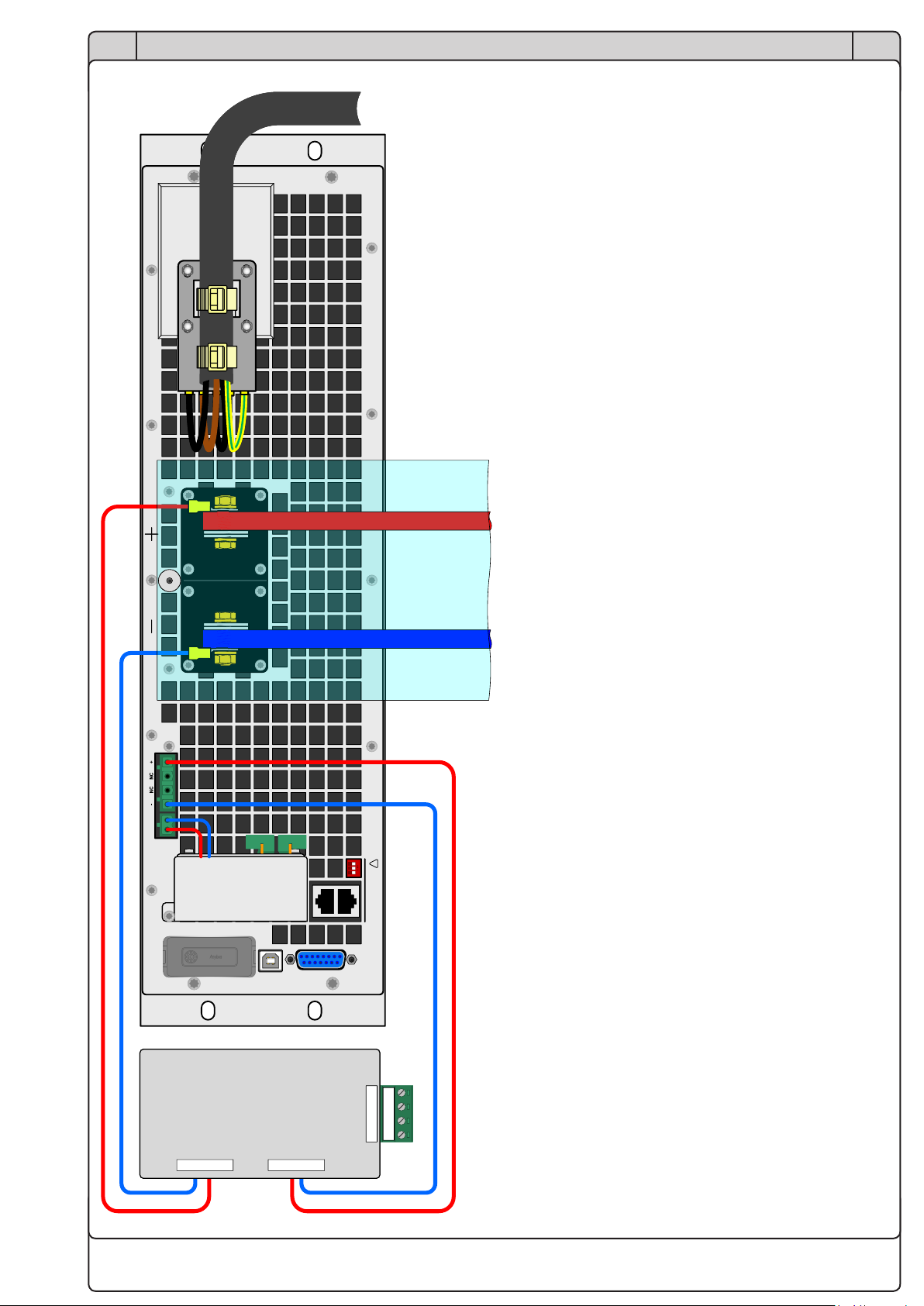
18
EN
Installationsanleitung / Installation guide
09114664
DE
C&KC&K
COMMUNICATION PORTCOMMUNICATION PORT
Share Sense
- +
Digi tal
Interface
USB
Analog
In t er face Master / Slave !
L3
L2
L1 L3
L2
L1 L3
L2
L1
External sense
External sense
DC bus Master Sense Master
External sense
External sense
DC bus Master Sense Master
Bild 6 - Schema der Fernfühlungs-Verdrahtung am Master (von hinten gesehen)
Figure 6 - Remote sense wiring scheme at the master (seen from the rear)
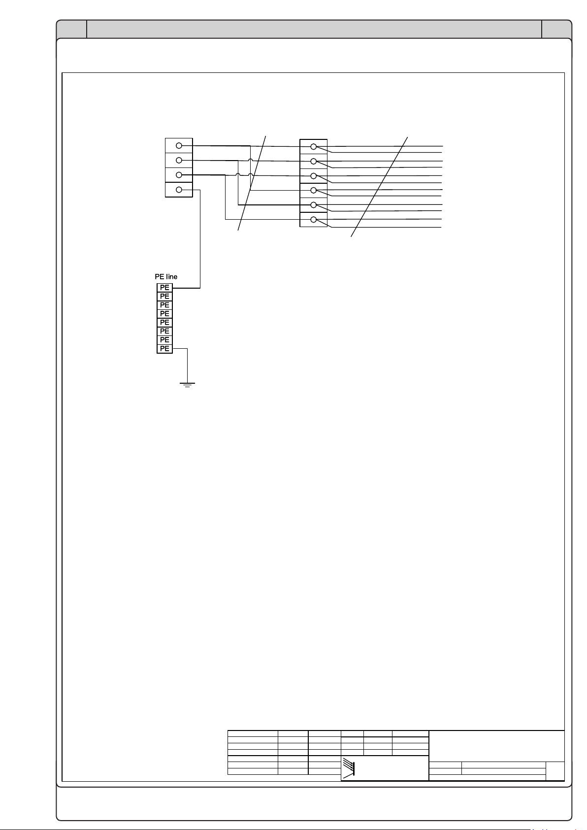
19
EN
Installationsanleitung / Installation guide
09114664
DE
Verdrahtungsplan Wiring schematic
Pa ge
1 vo n 4
E
AEA - Elektro Automatik
Wiring scheme
EA-PSB Rack 47 HE for 12x
PSB 91500-30 3U
Rev ‘d :
Created :
Da te Name
CAD S ystem M icroso ft Vi sio
Artikel Nr. : 09114664
File name :
Checked :
04.12.2018 H. Fü llgrabe
Da te NameChan ge noti ce
09114664_VP-S chr ank_03.vs dx
04.12.2018 H. Fü llgrabe
04.12.2018 H. Fü llgrabe
X10X10
L1
PE
L3
L2
X 1
NSGAFÖU
Blk 70mm2
2L1
2L2
2L3
3L1
3L2
3L3
NSGAFÖU
Blk 25mm2
Input
terminals
4 x 70...240mm2
Recommended
fusing 350A
PE distribution
blk
blk
blk
Recommended
input cross section
150...240mm2
blk
gn/ye
X 2
4L1
4L2
4L3
5L1
5L2
5L3
L1
L2
L3
L11
L22
L33

20
EN
Installationsanleitung / Installation guide
09114664
DE
Pa ge
2 vo n 4
E
AEA - Elektro Automatik
Wiring scheme
EA-PSB Rack 47 HE for 12x
PSB 91500-30 3U
Rev ‘d :
Created :
Da te Name
CAD S ystem M icroso ft Vi sio
Artikel Nr. : 09114664
File name :
Checked :
04.12.2018 H. Fü llgrabe
Da te NameChan ge noti ce
09114664_VP-S chr ank_03.vs dx
04.12.2018 H. Fü llgrabe
04.12.2018 H. Fü llgrabe
F13...F6 F6...F1
X1
PSB 9 1500-30
Unit 1
L1/L2/L3/ PE
M / S
Sharebus
M / S
Sharebus
M / S
Sharebus
X1
PSB 9 1500-30
Unit 1
L1/L2/L3/ PE
M / S
Sharebus +
-
X1
PSB 9 1500-30
Unit 1
L1/L2/L3/ PE
M / S
Sharebus +
-
L1
L2
L3
N
PE
X1
PSB 9 1500-30
Unit 1
L1/L2/L3/ PE
M / S
Sharebus +
-
L1
L2
L3
N
PE
X1
PSB 9 1500-30
Unit 2
L1/L2/L3/ PE
M / S
Sharebus
M / S
Sharebus
M / S
Sharebus
X1
PSB 9 1500-30
Unit 2
L1/L2/L3/ PE
M / S
Sharebus +
-
X1
PSB 9 1500-30
Unit 2
L1/L2/L3/ PE
M / S
Sharebus +
-
L1
L2
L3
N
PE
X1
PSB 9 1500-30
Unit 2
L1/L2/L3/ PE
M / S
Sharebus +
-
L1
L2
L3
N
PE
X1
PSB 9 1500-30
Unit 3
L1/L2/ L3/PE
M / S
Sharebus
M / S
Sharebus
M / S
Sharebus
X1
PSB 9 1500-30
Unit 3
L1/L2/ L3/PE
M / S
Sharebus +
-
X1
PSB 9 1500-30
Unit 3
L1/L2/ L3/PE
M / S
Sharebus +
-
L1
L2
L3
N
PE
X1
PSB 9 1500-30
Unit 3
L1/L2/ L3/PE
M / S
Sharebus +
-
L1
L2
L3
N
PE
X1
PSB 9 1500-30
Unit 4
L1/L2/L3/ PE
M / S
Sharebus
M / S
Sharebus
M / S
Sharebus
X1
PSB 9 1500-30
Unit 4
L1/L2/L3/ PE
M / S
Sharebus +
-
X1
PSB 9 1500-30
Unit 4
L1/L2/L3/ PE
M / S
Sharebus +
-
L1
L2
L3
N
PE
X1
PSB 9 1500-30
Unit 4
L1/L2/L3/ PE
M / S
Sharebus +
-
L1
L2
L3
N
PE
X1
PSB 9 1500-30
Unit 6
L1/L2/L3/ PE
M / S
Sharebus
M / S
Sharebus
M / S
Sharebus
X1
PSB 9 1500-30
Unit 6
L1/L2/L3/ PE
M / S
Sharebus +
-
X1
PSB 9 1500-30
Unit 6
L1/L2/L3/ PE
M / S
Sharebus +
-
L1
L2
L3
N
PE
X1
PSB 9 1500-30
Unit 6
L1/L2/L3/ PE
M / S
Sharebus +
-
L1
L2
L3
N
PE
X1
PSB 9 1500-30
Unit 7
L1/L2/L3/ PE
M / S
Sharebus
M / S
Sharebus
M / S
Sharebus
X1
PSB 9 1500-30
Unit 7
L1/L2/L3/ PE
M / S
Sharebus +
-
X1
PSB 9 1500-30
Unit 7
L1/L2/L3/ PE
M / S
Sharebus +
-
L1
L2
L3
N
PE
X1
PSB 9 1500-30
Unit 7
L1/L2/L3/ PE
M / S
Sharebus +
-
L1
L2
L3
N
PE
X1
PSB 9 1500-30
Unit 8
L1/L2/L3/ PE
M / S
Sharebus
M / S
Sharebus
M / S
Sharebus
X1
PSB 9 1500-30
Unit 8
L1/L2/L3/ PE
M / S
Sharebus +
-
X1
PSB 9 1500-30
Unit 8
L1/L2/L3/ PE
M / S
Sharebus +
-
L1
L2
L3
N
PE
X1
PSB 9 1500-30
Unit 8
L1/L2/L3/ PE
M / S
Sharebus +
-
L1
L2
L3
N
PE
X1
PSB 9 1500-30
Unit 9
L1/L2/L3/ PE
M / S
Sharebus
M / S
Sharebus
M / S
Sharebus
X1
PSB 9 1500-30
Unit 9
L1/L2/L3/ PE
M / S
Sharebus +
-
X1
PSB 9 1500-30
Unit 9
L1/L2/L3/ PE
M / S
Sharebus +
-
L1
L2
L3
N
PE
X1
PSB 9 1500-30
Unit 9
L1/L2/L3/ PE
M / S
Sharebus +
-
L1
L2
L3
N
PE
32A32A32A
32A32A 32A 32A32A32A32A32A 32A
4L1
4L2
4L3
NSGAFÖU
25mm2
32A32A32A
32A32A32A32A32A 32A
2L1
2L2
2L3
NSGAFÖU
25mm2
Bus bar 4
P S3 /11
Bus bar 1
P S3 /9
6L1 blk 6mm2
6L2 blk 6mm2
6L3 blk 6mm2
7L1 blk 6mm2
7L2 blk 6mm2
7L3 blk 6mm2
8L1 blk 6mm2
8L2 blk 6mm2
8L3 blk 6mm2
9L1 blk 6mm2
9L2 blk 6mm2
9L3 blk 6mm2
10L1 blk 6mm2
10L2 blk 6mm2
10L3 blk 6mm2
11L1 blk 6mm2
11L2 blk 6mm2
11L3 blk 6mm2
14L1 blk 6mm2
14L2 blk 6mm2
14L3 blk 6mm2
15L1 blk 6mm2
15L2 blk 6mm2
15L3 blk 6mm2
All power supply wires
are NSGAFÖU
X1
PSB 9 1500-30
Unit 5
L1/L2/L3/ PE
M / S
Sharebus
M / S
Sharebus
M / S
Sharebus
X1
PSB 9 1500-30
Unit 5
L1/L2/L3/ PE
M / S
Sharebus +
-
X1
PSB 9 1500-30
Unit 5
L1/L2/L3/ PE
M / S
Sharebus +
-
L1
L2
L3
N
PE
X1
PSB 9 1500-30
Unit 5
L1/L2/L3/ PE
M / S
Sharebus +
-
L1
L2
L3
N
PE
X1
PSB 9 1500-30
Unit 10
L1/L2/L3/ PE
M / S
Sharebus
M / S
Sharebus
M / S
Sharebus
X1
PSB 9 1500-30
Unit 10
L1/L2/L3/ PE
M / S
Sharebus +
-
X1
PSB 9 1500-30
Unit 10
L1/L2/L3/ PE
M / S
Sharebus +
-
L1
L2
L3
N
PE
X1
PSB 9 1500-30
Unit 10
L1/L2/L3/ PE
M / S
Sharebus +
-
L1
L2
L3
N
PE
32A32A 32A32A32A 32A
32A32A 32A32A32A 32A
32A32A 32A32A32A 32A
16L1 blk 6mm2
16L2 blk 6mm2
16L3 blk 6mm2
17L1 blk 6mm2
17L2 blk 6mm2
17L3 blk 6mm2
3L1
3L2
3L3
Bus bar 2
P S3 /9
NSGAFÖ
25mm2
Bus bar 3
P S3 /9
5L1
5L2
5L3
NSGAFÖ
25mm2
X1
PSB 9 1500-30
Unit 11
L1/L2/L3/ PE
M / S
Sharebus
M / S
Sharebus
M / S
Sharebus
X1
PSB 9 1500-30
Unit 11
L1/L2/L3/ PE
M / S
Sharebus +
-
X1
PSB 9 1500-30
Unit 11
L1/L2/L3/ PE
M / S
Sharebus +
-
L1
L2
L3
N
PE
X1
PSB 9 1500-30
Unit 11
L1/L2/L3/ PE
M / S
Sharebus +
-
L1
L2
L3
N
PE
X1
PSB 9 1500-30
Unit 12
L1/L2/L3/ PE
M / S
Sharebus
M / S
Sharebus
M / S
Sharebus
X1
PSB 9 1500-30
Unit 12
L1/L2/L3/ PE
M / S
Sharebus +
-
X1
PSB 9 1500-30
Unit 12
L1/L2/L3/ PE
M / S
Sharebus +
-
L1
L2
L3
N
PE
X1
PSB 9 1500-30
Unit 12
L1/L2/L3/ PE
M / S
Sharebus +
-
L1
L2
L3
N
PE
32A32A 32A32A32A 32A
32A32A 32A32A32A 32A
16A 16A16A 16A
12L1 blk 6mm2
12L2 blk 6mm2
12L3 blk 6mm2
13L1 blk 6mm2
13L2 blk 6mm2
13L3 blk 6mm2
X1
MW 120-24
Unit 13
L 1/ L 2/ PE
X1
MW 120-24
Unit 13
L 1/ L 2/ PE
24V=
18L1 blk 1,5mm2
18L2 blk 1,5mm2
SBA 9 000
Master
Sharebus
+
-
+VCC P GN D Sh ie ld
SB SB -R TN +VCC P GN D Sh ie ld
SBA 9 000
Master
Sharebus
+
-
+VCC P GN D Sh ie ld
SB SB -R TN +VCC P GN D Sh ie ld
1 2 3
X4
X1 1 2 3 4 5
SBA 9 000
Master
Sharebus
+
-
+VCC P GN D Sh ie ld
SB SB -R TN +VCC P GN D Sh ie ld
1 2 3
X4
X1 1 2 3 4 5
SBA 9 000
S l av e
Sharebus
+
-
SB SB -R TN +VCC P GN D Sh ie ld
SB SB -R TN +VCC P GN D Sh ie ld
X4
X1
1 2 3 4 5
1 2 3 4 5
SBA 9 000
S l av e
Sharebus
+
-
SB SB -R TN +VCC P GN D Sh ie ld
SB SB -R TN +VCC P GN D Sh ie ld
X4
X1
1 2 3 4 5
1 2 3 4 5
75525001
4x1mm2
SBA 9 000
S l av e
Sharebus
+
-
SB SB -R TN +VCC P GN D Sh ie ld
SB SB -R TN +VCC P GN D Sh ie ld
X4
X1
1 2 3 4 5
1 2 3 4 5
SBA 9 000
S l av e
Sharebus
+
-
SB SB -R TN +VCC P GN D Sh ie ld
SB SB -R TN +VCC P GN D Sh ie ld
X4
X1
1 2 3 4 5
1 2 3 4 5
SBA 9 000
S l av e
Sharebus
+
-
SB SB -R TN +VCC P GN D Sh ie ld
SB SB -R TN +VCC P GN D Sh ie ld
X4
X1
1 2 3 4 5
1 2 3 4 5
SBA 9 000
S l av e
Sharebus
+
-
SB SB -R TN +VCC P GN D Sh ie ld
SB SB -R TN +VCC P GN D Sh ie ld
X4
X1
1 2 3 4 5
1 2 3 4 5
SBA 9 000
S l av e
Sharebus
+
-
SB SB -R TN +VCC P GN D Sh ie ld
SB SB -R TN +VCC P GN D Sh ie ld
X4
X1
1 2 3 4 5
1 2 3 4 5
SBA 9 000
S l av e
Sharebus
+
-
SB SB -R TN +VCC P GN D Sh ie ld
SB SB -R TN +VCC P GN D Sh ie ld
X4
X1
1 2 3 4 5
1 2 3 4 5
SBA 9 000
S l av e
Sharebus
+
-
SB SB -R TN +VCC P GN D Sh ie ld
SB SB -R TN +VCC P GN D Sh ie ld
X4
X1
1 2 3 4 5
1 2 3 4 5
SBA 9 000
S l av e
Sharebus
+
-
SB SB -R TN +VCC P GN D Sh ie ld
SB SB -R TN +VCC P GN D Sh ie ld
X4
X1
1 2 3 4 5
1 2 3 4 5
SBA 9 000
S l av e
Sharebus
+
-
SB SB -R TN +VCC P GN D Sh ie ld
SB SB -R TN +VCC P GN D Sh ie ld
X4
X1
1 2 3 4 5
1 2 3 4 5
SBA 9 000
S l av e
Sharebus
+
-
SB SB -R TN +VCC P GN D Sh ie ld
SB SB -R TN +VCC P GN D Sh ie ld
X4
X1
1 2 3 4 5
1 2 3 4 5
SBA 9 000
S l av e
Sharebus
+
-
SB SB -R TN +VCC P GN D Sh ie ld
SB SB -R TN +VCC P GN D Sh ie ld
X4
X1
1 2 3 4 5
1 2 3 4 5
SBA 9 000
S l av e
Sharebus
+
-
SB SB -R TN +VCC P GN D Sh ie ld
SB SB -R TN +VCC P GN D Sh ie ld
X4
X1
1 2 3 4 5
1 2 3 4 5
SBA 9 000
S l av e
Sharebus
+
-
SB SB -R TN +VCC P GN D Sh ie ld
SB SB -R TN +VCC P GN D Sh ie ld
X4
X1
1 2 3 4 5
1 2 3 4 5
SBA 9 000
S l av e
Sharebus
+
-
SB SB -R TN +VCC P GN D Sh ie ld
SB SB -R TN +VCC P GN D Sh ie ld
X4
X1
1 2 3 4 5
1 2 3 4 5
SBA 9 000
S l av e
Sharebus
+
-
SB SB -R TN +VCC P GN D Sh ie ld
SB SB -R TN +VCC P GN D Sh ie ld
X4
X1
1 2 3 4 5
1 2 3 4 5
SBA 9 000
S l av e
Sharebus
+
-
SB SB -R TN +VCC P GN D Sh ie ld
SB SB -R TN +VCC P GN D Sh ie ld
X4
X1
1 2 3 4 5
1 2 3 4 5
SBA 9 000
S l av e
Sharebus
+
-
SB SB -R TN +VCC P GN D Sh ie ld
SB SB -R TN +VCC P GN D Sh ie ld
X4
X1
1 2 3 4 5
1 2 3 4 5
SBA 9 000
S l av e
Sharebus
+
-
SB SB -R TN +VCC P GN D Sh ie ld
SB SB -R TN +VCC P GN D Sh ie ld
X4
X1
1 2 3 4 5
1 2 3 4 5
SBA 9 000
S l av e
Sharebus
+
-
SB SB -R TN +VCC P GN D Sh ie ld
SB SB -R TN +VCC P GN D Sh ie ld
X4
X1
1 2 3 4 5
1 2 3 4 5
SBA 9 000
S l av e
Sharebus
+
-
SB SB -R TN +VCC P GN D Sh ie ld
SB SB -R TN +VCC P GN D Sh ie ld
X4
X1
1 2 3 4 5
1 2 3 4 5
75525001
4x1mm2
75525001
4x1mm2
75525001
4x1mm2
75525001
4x1mm2
75525001
4x1mm2
75525001
4x1mm2
75525001
4x1mm2
75525001
4x1mm2
75525001
4x1mm2
75525001
4x1mm2
SB+ red
SB- blue
SB+ red
SB- blue
SB- blue
SB- blue
SB- blue
SB- blue
SB- blue
SB- blue
SB- blue
SB- blue
SB- blue
SB- blue
SB+ red
SB+ red
SB+ red
SB+ red
SB+ red
SB+ red
SB+ red
SB+ red
SB+ red
SB+ red
GND
+24V
+24V
GND
60 red 1,5mm2
61 blue 1,5mm2
Table of contents
Other Elektro-Automatik Enclosure manuals


