Elektron Technology bulgin Buccaneer 900 Series User manual
900 Series
Buccaneer
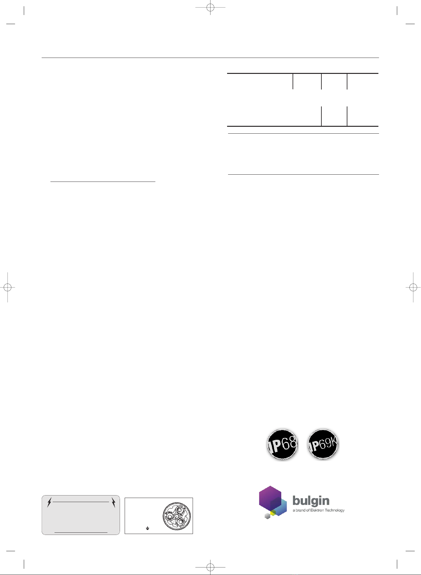
IP68 and IP69K Waterproof Connectors
Wiring Assembly Instructions
www.bulgin.co.uk
Buccaneer 900 Series Environmentally Sealed Connectors
Mains Wire Connections
Important connect wires
Brown to termina L
B ue to termina N
Green/Ye ow to
termina E
Material:
Body Mouldings: Polyamide
Flammability Rating: UL94V-0
Contacts: Machined Solid Brass, Nickel plated
O Rings: Nitrile
Panel Sealing Gasket: Silicone Rubber
Mechanical:
Sealing: P69K, EN60529
Contact Accommodation: 2.5 to 4mm2 (13-10AWG) conductor, single or
multi stranded
Cable Retention force: 22mm dia, 150N
15mm dia, 150N
7mm dia, 80N
Cable Acceptance and
Gland Tightening Torques:
Cable dia Gland Colour Tightening Torque
PX0 version 13-15mm Yellow (standard)
3.16Nm (28 lb/in)
11-13mm Black
3.16Nm (28 lb/in)
9-11mm White
3.16Nm (28 lb/in)
7-9mm Dark Grey
3.16Nm (28 lb/in)
PXA version 20-22mm Yellow (standard)
3.16Nm (28 lb/in)
18-20mm Black
3.16Nm (28 lb/in)
16-18mm White
3.16Nm (28 lb/in)
14-16mm Dark Grey
3.16Nm (28 lb/in)
Panel mount nut --
2.25Nm
Flange & Bulkhead
fixing screws --
0.9Nm
IMPO TANT - PLEASE EAD
Before usin the connector, it is important that these instructions are carefully
read and understood to ensure the connector system is completely water ti ht
and electrically safe.
IF IN DOUBT CONSULT A QUALIFIED ELECTRICIAN.
NEVER UNMATE OR MATE THE PRODUCT WHILE STILL UNDER LOAD
The 900 Series Buccaneer is available in 2, 3, 4, 5, 7 and 10 pole
versions. The 3, 4, 5 and 7 pole versions have a ‘Leading Earth’ pin
arrangement for added protection.
The socket insert of the connector should always be the live part of the
connector from the supply. The pin insert of the connector should always lead
to the load or electrical device. The pin or socket inserts can be fitted to any
body style to provide the correct arrangement for the application.
To ensure efficient sealing use only smooth, circular cable with appropriate
gland for the cable diameter. The sealing glands supplied with the Flex and
Flex n-line connectors accommodate cables sizes as follows:
Version Cable Dia. Cable Gland Colour
PX0 13-15mm Yellow (standard)
PX0 11-13mm Black
PX0 9-11mm White
PX0 7-9mm Dark Grey
PXA 20-22mm Yellow (standard)
PXA 18-20mm Black
PXA 16-18mm White
PXA 14-16mm Dark Grey
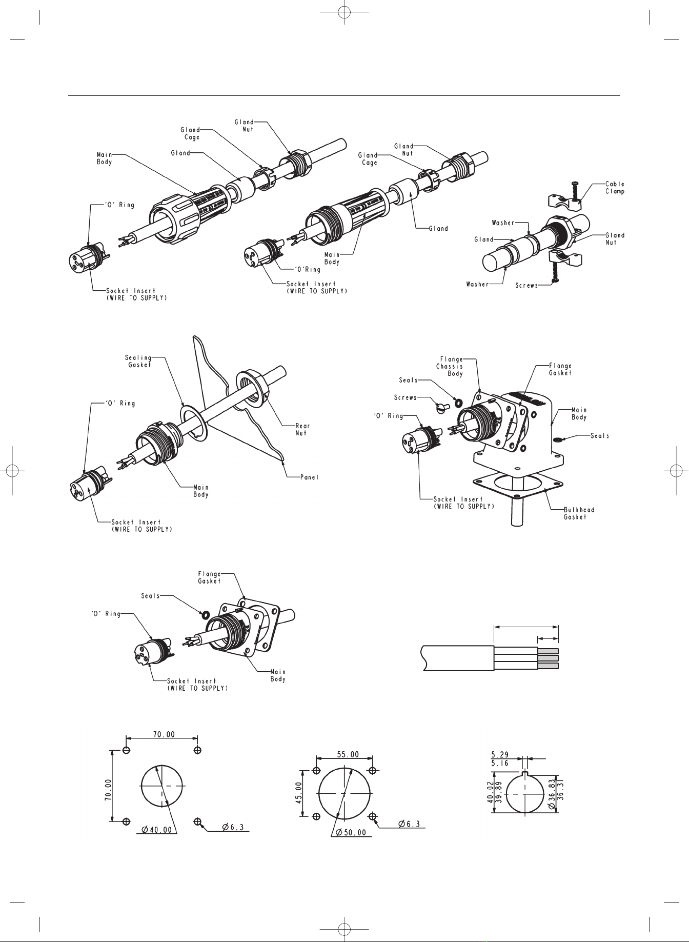
Assembly/Wiring instructions
1. Remove the pin or socket insert from the housing of the connector.
There is a slot for a flat blade screwdriver in the centre of the insert.
NOTE: The inserts have a LEFT HAND THREAD and should be turned
clockwise to remove.
2. For Flex and n-Line connector bodies, remove the gland nut, gland
cage and gland from the rear of the housing and slide onto the
cable. NOTE for PXA version there is no gland cage. Thread the
cable through the connector body. See assembly drawings, figs. 1-5
and 8 for different body styles.
3. Prepare the cable and bare the wire ends as shown in fig. 6, wire
stripping details.
4. nsert the bared wire ends into the terminals on the back of the
pin/socket insert and fully tighten the wire retention screws.
NOTE: f the connector is to be used with ‘mains’ voltages, ensure
the wires are connected in the correct orientation as shown in the
diagram below.
After the wires have been connected securely, pull the cable and
insert back into the housing and tighten with a screwdriver to ensure
the insert is seated correctly.
NOTE: LEFT HAND THREAD, turn the insert anti-clockwise when
assembling.
When assembling the Chassis (fig 3) and Flange (fig 4 and 5)
housing types, the cable should be left free behind the panel to
prevent it twisting.
5. For Flex and Flex n-line housings:
PX0 version: Slide the gland, gland cage and gland nut along the
cable into the body and tighten the gland nut to the appropriate
torque to seal.
Please note change to PXA assembly:
PXA version: Slide 1 washer, the gland, the final washer and gland
nut along the cable into the body and tighten to the appropriate
torque to seal then tighten clamp screws to secure. See fig 8.
6. For the Bulkhead, Flange and Chassis body styles, correctly seat the
gaskets and housing onto the mounting surface and secure with rear
nut or screws/bolts with seals. Ensure all seals and glands are kept
clean during assembly.
NOTE: To ensure that the correct sealing properties of the connector are
achieved it is imperative that all ‘O’ rings are correctly located and
seated before assembly. Please refer to the exploded diagrams for the
locations of these seals.
Part no.: 13672 Issue no: 12
IF IN DO BT SEEK ADVICE
IMPORTANT SAFETY NOTICE
For your protection all mains (250V) equipment
used out of doors, in damp or wet conditions
should be supplied from a correctly fused
source and protected by an approved R.C.D. to
BS7071, BS7288, BS4293, BS EN 61008-1,
BS EN 1008-2-2
900 Series Wiring 13672iss12:900 Series Wiring 13672iss12 19/9/12 16:34 Page 1
Specification
Electrical:
Current Rating: CSA
Current Rating:
Voltage Rating:
Contact Resistance:
Insulation Resistance:
Dielectric strength:
Approvals:
4,5 Poles 7 Pole 10 Pole
32A
30A
600V ac/dc
32A
25A
600V ac/dc
2,3 Poles
32A
30A
415V ac/dc
10A
10A
250V ac/dc
<10m Ohm (initial)
>10M Ohm (@500V dc)
2.2Kv ac min
UL/VDE/CSA/CCC UL/VDE/CCC CCC
CSA Pending UL/VDE/CSA
Pending
ʻCaution not for Interrupting currentʼ
ʻAttention; Ne pas utiliser pour couper le courantʼ
22mm
7mm
Buccaneer 900 Series Environmentally Sealed Connectors
Fig 1. Flex Mounting
(PX0911, PXA911)
Fig 8. Cable retention and
sealing assembly for large
cable entry (PXA911, PXA921)
Fig 3. Chassis/Panel Mounting (PX0931) Fig 4. Flange/Bulkhead Mounting
(PX0941 + PX0950)
Fig 5. Flange Mounting (PX0941)
Fig 6. Wire Striping Details
Fig 7. Panel cut out details
Fig 2. Flex Mounting In-line
(PX0921, PXA921)
BULKHEAD/FLANGE MOUNTING PX0950 FLANGE MOUNTING PX0941 PANEL MOUNTING PX0931
900 Series Wiring 13672iss12:900 Series Wiring 13672iss12 19/9/12 16:34 Page 2
This manual suits for next models
17
Popular Cables And Connectors manuals by other brands

OBO Bettermann
OBO Bettermann V-TEC VM12UV LGR Mounting instructions

Amphenol
Amphenol Temposonics DT Connector System installation manual

Stihl
Stihl AP instruction manual

Thetford
Thetford Aqua-Magic V quick start guide

Schrack
Schrack HHDC2002 quick start guide

Renkforce
Renkforce 1407351 operating instructions


