Elektron MULTISPOT M80 User manual
Operating instructions
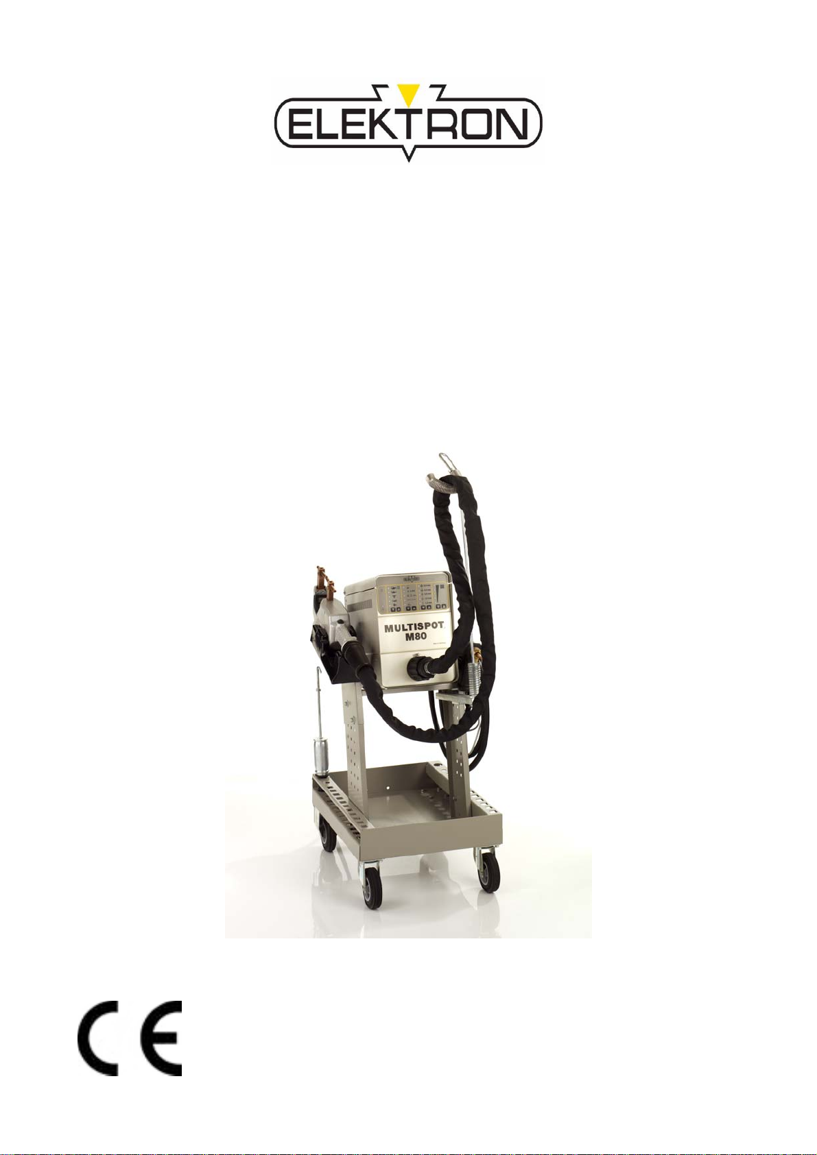
MULTISPOT M80
Resistance Welder
Item no. 322921
Revision: 3.0 - Translation
Version: 09th, March 2010
Be sure you have read and understood
this operating manual before you carry
out any works on and/or with this
equipment.

Contents page
1.0 Warning notes – explanation of symbols 1
2.0 Description of equipment and overview 3
3.0 Start-up 5
3.1 Assembly of power supply unit and trolley 5
3.2 Compressed air connection 5
3.3 Mains power supply connection 6
3.4 Checking the mains voltage drop during welding 6
3.5 Malfunction indicator 7
4.0 Applications 8
5.0 Technical data 9
6.0 Working with spot-welding tongs 11
6.1 Preparation of welding area 11
6.2 Spot-welding with the tongs 13
6.3 Pulse welding 15
7.0 Operating the welding gun 17
7.1 Push spot welding 19
7.2 Pulling-out dents with washer 21
7.3 Pulling-out dents with high-speed planishing hammer “SAH" 23
7.4 Pushing-in dents 25
7.5 Shrinking sheet metal 25
7.6 Welding-on threaded studs 27
7.7 Welding-on T-pins 29
7.8 Positioning/fixing sheet metal (tacking) 31
8.0 Operating QUICKSPOT 31
9.0 Connection of AIRPULLER 32
10.0 Practical hints 32
11.0 Appendix/self-test and troubleshooting 33
11.1 Self-test 33
11.2 Checking LED displays and the solenoid valves 33
11.3 Mains-supply test and troubleshooting 33
11.4 Manual tool selection 35
11.5 Operating panel malfunction 35
- 1 -
1.0 Warning notes – explanation of symbols
Caution!
Please note the following when using resistance welding units:
The power supply unit and leads of the welding gun and the spot
welding tongs generate a powerful electromagnetic field when in use.
Electromagnetic fields can cause irritations of sense organs, nerve
and muscle cells as well as malfunctions in physical aids (hearing aid,
pacemaker etc.), electronic devices and data storage units.
To prevent these effects, avoid a direct body contact with the welding
cable. A safe distance of 15 cm between cable and body is
recommended.
Caution! Danger!
Ignoring this warning may result in injury!
Observe the notes!
This is the only way to achieve satisfactory welding results.
Work on the power supply unit may ONLY be performed by qualified
electricians.
Wear protective goggles and gloves!

- 2 -
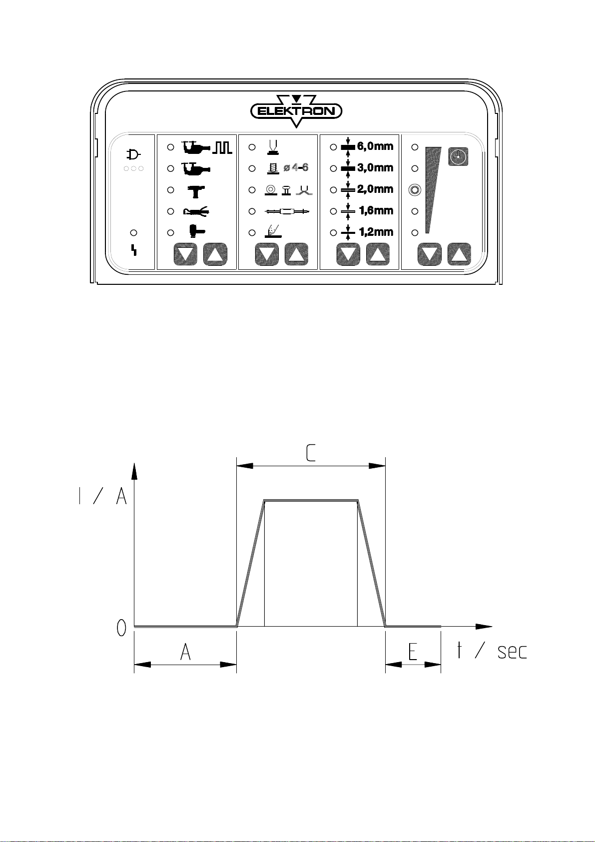
AB Tool selecting keys (manual) see Appendix
CD Gun functions selecting keys
EF Sheet thickness selecting keys
GH Fine adjustment keys time +/–
Tools
1 Tongs, pulse welding
2 Tongs, spot welding
3 Gun
4 QUICKSPOT
5 AIRPULLER
Working with gun
6 Push spot welding
7 Stud welding
8 Beat-out with washers, T-pins, riveting dies
9 High-speed planishing hammer
10 Anneal/shrink
11 Sheet thickness selector
12 Fine adjustment +/–
13 Mains plug symbos with LED “control mains voltage drop” (15, 16, 17)
14 LED malfunction

- 3 -
2.0 Description of equipment and overview
The MULTISPOT M80 resistance welding unit is designed for the
special requirements of motor vehicle body repair.
The power source is controlled by a micro-processor. After selecting the operating
mode and the sheet steel thickness, the current and weld time will be assigned
automatically and – where necessary and advisable – corrected accordingly. An
audible alarm is performed, if the welding current is too low.
Further functions:
– Automatic tool recognition
– Integrated mains monitor recognises undervoltage
– Automatic current rise, welding, current recognition and repressing
– Easy and distinct operation by means of foil keyboard
– Thermal probe controlled air-cooling for gun and tongs
– Central connection for welding current, compressed air, cooling and control
wiring
– Closed box for accessories in power supply unit
– Sturdy trolley with basin for tools and accessories and electrode arms
60 Tongs holder * * in connection with spot
61 Cable holder welding tongs
62 Trolley frame **special accessories (item no.
63 Central connection socket pls. see from accessories list)
64 Balancer **
65 Filter pressure reducer
66 Mains switch
67 Service box
68 Power supply unit
69 Screws 8 x 16
70 Screws 8 x 16
71 Trolley base
72 Roller
73 Guide wheel
74 Receptacle for pulling tool + SAH
75 Receptacle for electrode arms
76 Fastening screws
77 Electronics / operation panel

- 4 -
- 5 -
3.0 Start-up
3.1 Assembly of power supply unit and trolley
– Screw frame (62) to the trolley base with the screws provided (70)
– Put power supply unit (68) on the trolley and fasten with screws
provided (76).
– Screw tongs holder* (60), cable holder (61), balancer** (64)
to the frame.
– (*= in connection with spot welding tongs
**= special accessories)
item number please see from accessories list).
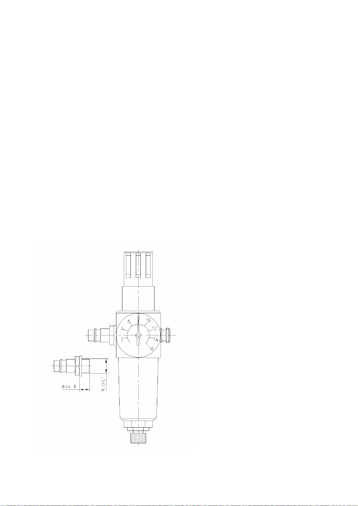
3.2 Compressed air connection
Connection to a compressed air supply is necessary for operation of the
MULTISPOT M80 in conjunction with the spot welding tongs! The connection with
adjustable filter/pressure reducer (65) is located on the back of the power supply
unit (68). The operating pressure is 8 bar!
Insufficient pressure reduces the electrode contact pressure and increases
electrode wear. Excessive pressure can cause poor welding quality and
damage to the tongs.
When installing another air
connection, ensure that the thread of
the plug connector is screwed into the
filter pressure reducer no deeper than
8 mm, as otherwise the air supply will
be interrupted.
Seal the thread with Loctite.

- 6 -
3.3 Mains power supply connection
400 V 50/60 Hz (automatic switch-over)
Connection to a 32 A Cekon socket
Fuse: 32/35 A slow fuse
or
32 A automatic circuit-breaker
230 V (190-240 V) 50/60 Hz (automatic switch-over)
Connection to a 63 A Cekon socket
Fuse: 63 A slow fuse
or
63 A automatic circuit-breaker
3.4 Checking the mains voltage drop during welding
If the full performance of the MULTISPOT M80 is to be obtained, the mains
voltage drop during welding must be kept as small as possible.
The full test is described on Page 35, Chapter 11.3:
Information about the mains drop during welding
Display with 3 LEDs (15, 16, 17) under the mains plug symbol:
Green = mains OK
Green/yellow = mains drop within tolerance range.
Only yellow = considerable mains drop – welding performance
impaired
If necessary, check mains cord, extension cables etc. or use thicker cables.
Red and = large mains drop with large drop in performance.
warning tone: Welding is not possible. Welding current too low.
If necessary, check mains cord, extension cables etc. or use thicker cables.
After 2 seconds, the display automatically reverts to green.
After each welding operation, any mains voltage drop is displayed
for 2 seconds.

- 7 -
3.5 Malfunction indicator
The red LED (14) indicates
thermal overloading of the
spot-welding tongs/spot-
welding gun. While the LED
(14) is glowing, it is not
possible to continue welding
with the tool connected. The
unit is ready for use again
after the LED (14) has
extinguished.

- 8 -
4.0 Applications
Welding capacity:
Compressed-air pressure 8 bar
Electrode arm 120 mm
Programme switch Material Sheet thickness
Function in mm
Pulse welding with pneu-
matic spot welding tongs sheet steel 3.0 + 3.0
Spot welding with sheet steel 2.0 + 2.0
spot welding tongs pneumatic galvanized steel 1.5 + 1.5
Spot welding with
QUICKSPOT sheet steel 1.0 + 1.0
Push spot welding sheet steel 1.25 + 1.25
Setting for the following functions:
e. g. for sheet thickness 0.8 mm – choose range 1.6 mm
= 2 x 0.8 mm
Straightening out
with washer sheet steel 1.2
Airpuller sheet steel 1.0
Straightening out with
high-speed
planishing hammer sheet steel 0.8
Shrinking sheet steel 0.6 – 1.0
Stud welding Steel bolts Æ 4 – 6 mm
on sheet steel 2.0 mm

- 9 -
5.0 Technical data
Power supply unit
Supply voltage 400 V (380-415 V) 230V (190-240 V)
Slow fuse 32/35 A* 63 A*
Mains frequency 50/60 Hz 50/60 Hz
Power supply cord 14.7 kVA 14.7 kVA
Max. welding capacity 45 kVA 45 kVA
Open-circuit voltage 12 V 12 V
Welding current 6400A, 6400A,
3% duty cycle 3% duty cycle
Welding time** 0.03 – 0.9 s 0.03 – 0.9 s
automatic automatic
adjustment adjustment
Pulse welding time** 0.1 – 1.5 s 0.1 – 1.5 s
automatic automatic
adjustment adjustment
Ambient temperature 40° C 40° C
Type of protection IP21 IP21
Dimensions H/W/D mm 375/265/535 375/265/535
Weight power supply unit 54.5 kg 54.5 kg
Dimensions of power supply
unit in trolley H/W/D in mm 1020/517/600 1020/517/600
Total weight inc. accessories approx. 97.1 kg approx. 97.1 kg
Spot welding tongs (pneumatic)
Weight (without cable) 3.5 kg 3.5 kg
Weight (with cable) 11.5 kg 11.5 kg
Operating pressure 8 bar 8 bar
Electrode arms 20 x 20 mm 20 x 20 mm
Electrode contact pressure 1800 N 1800 N
Welding cable Ø/length 120 mm²/2.5 m 120 mm²/2.5 m
Electrodes Ø 12 mm
Push spot welder
Welding cable Ø /length 120 mm² / 2.2 m 120 mm² / 2.2 m
Earth cable Ø /length 120 mm / 1.5 m 120 mm / 1.5 m
Weight 6.15 kg 6.15 kg
Electrodes Ø 10 mm 10 mm
**Operation with a lower rating fuse at reduced power is possible.
**+ automatic correction

- 10 -
24 Spot welding tongs
25 Electrode arm, stationary, 20 x 20 mm (square)
26 Electrode arm, movable, 20 x 20 mm
27 Welding electrodes with caps
28 Momentary contact button
29 Handle groove
30 Release button for movable electrode arm
31 Welding cable
32 Electrode arm receptacle

- 11 -
6.0 Working with the spot-welding tong
Caution! Switch off power supply unit or set to “push spot
welding” mode during breaks or when changing electrodes
or adjusting electrode spacing!
Otherwise danger of crushing!
– Insert the central plug of the spot welding tongs – with arrow
pointing upwards – into the central socket (63) of the power
supply unit until limit stop.
– The unit will switch over to symbol “tongs” automatically.
– When using uncoded tongs, set to “tongs” symbol with keys
AB.
– Tighten the sleeve nut of the central connection by turning
clockwise.
– Insert electrode arms (25 and 26) in tongs.
– Make sure the movable electrode arm (26) clicks home.
– Insert and adjust electrodes (27).
– Electrode spacing 6 to max. 8 mm.
– Check with size 6 Allen key.
– Tighten socket-head cap screws.
– Re-check electrode spacing after the initial spot welding
procedures and re-adjust, if necessary!
The condition of the electrode caps is essential for proper weld-
ing results! Change or grind worn caps!
For item no. of the cutter please see Accessory List!
The electrode caps can easily be changed by turning with pliers.
Simply place fresh electrode caps on the taper of the electrode
and press in position.
In order to accommodate bulky body parts, such as door sills and
posts, the movable electrode arm (26) can be released by
pressing the release button (30). When the electrode arms (25)
and (26) are pressed together manually, the arm will engage
automatically.
6.1 Preparation of the welding area
The area of the sheets to be welded should be ground to a bright
metal finish.
Important! The contact points of electrode cap to sheet and
sheet to sheet must be absolutely free of grinding swarf,
paint residues and rust. Otherwise welding will cause
- 12 -
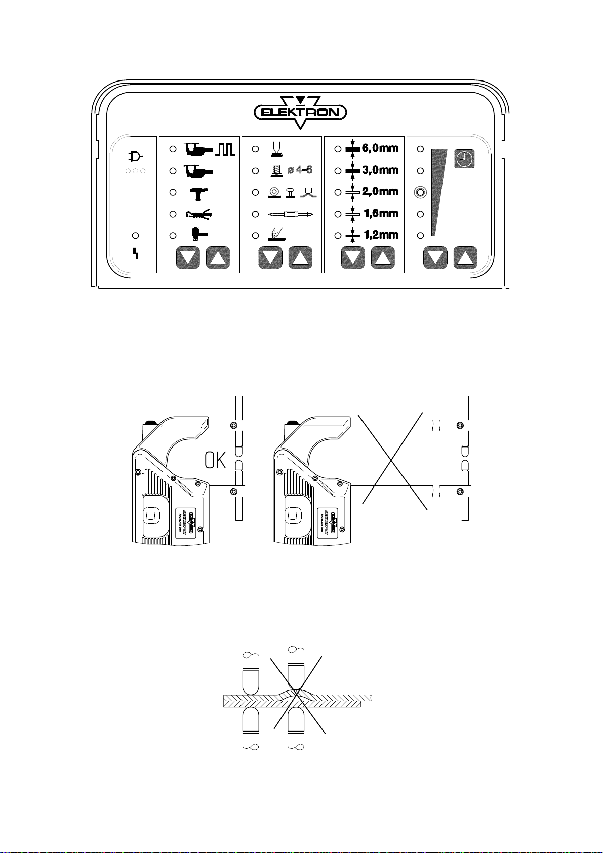
A B C D E F G H

- 13 -
6.2 Spot-welding with the tongs
Caution:
Electromagnetic fields!
Wear protective goggles and gloves!
Electrodes heat up!
Flying sparks!
– Switch on unit with mains switch (66).
– Connect unit to the compressed air supply.
Ensure sufficient compressed air pressure, operating
pressure is 8 bar! If necessary, adjust pressure with the
filter pressure reducer (65). Insufficient compressed air
will lead to excessive splatter and the weld spot may
burn out.
When the spot-welding tongs have been connected, the unit
will switch automatically to the “tongs” symbol.
In the case of uncoded tongs, select the “tong spot-welding”
function with the program key AB, set sheet thickness with
key EF; if necessary fine-adjust with key GH, e. g. galvanized
sheets +, stainless steel sheets –.
During welding procedures, keep hold of button of the tongs
until welding process is automatically cut-off.
Sequence of the welding program (see diagram on LHS):
A – Pre-pressing 0.75 sec
C – Welding with automatic timer-setting 0.03 to 0.45 sec
E – Re-pressing 0.5 sec.
Releasing key (28) prematurely will interrupt the
functions “Pre-pressing” and “Welding”. Continued
pressure on key (28) can extend the function “Re-press”.
- 14 -
A B C D E F G H

- 15 -
6.3 Pulse welding
Caution:
Electromagnetic fields!
Wear protective goggles and gloves!
Electrodes heat up!
Flying sparks!
This mode is used for spot-welding sheet metal of 2 x 1.5 mm
or more, such as e.g. frame parts and gusset flanges.
Preparations:
– Ensure precise fitting of the sheets to be welded – no air
gap!
– Clean sheets.
– Electrode arms no longer than 250 mm.
– Stable mains power supply.
– Air pressure minimum 8 bar at filter pressure reducer.
Welding:
– Select mode “Tongs – pulse welding” with keys AB.
– Select sheet thickness with keys EF.
– Keep hold of key (28) of the tongs until welding process is
cut-off automatically.
– Observe intervals of approx. 10 secs. Between spots to
prevent electrode caps from annealing.
– The pulse welding option should only be used in the
exceptional cases mentioned above.
– Overload: Continue welding once the red LED has
extinguished.

- 16 -
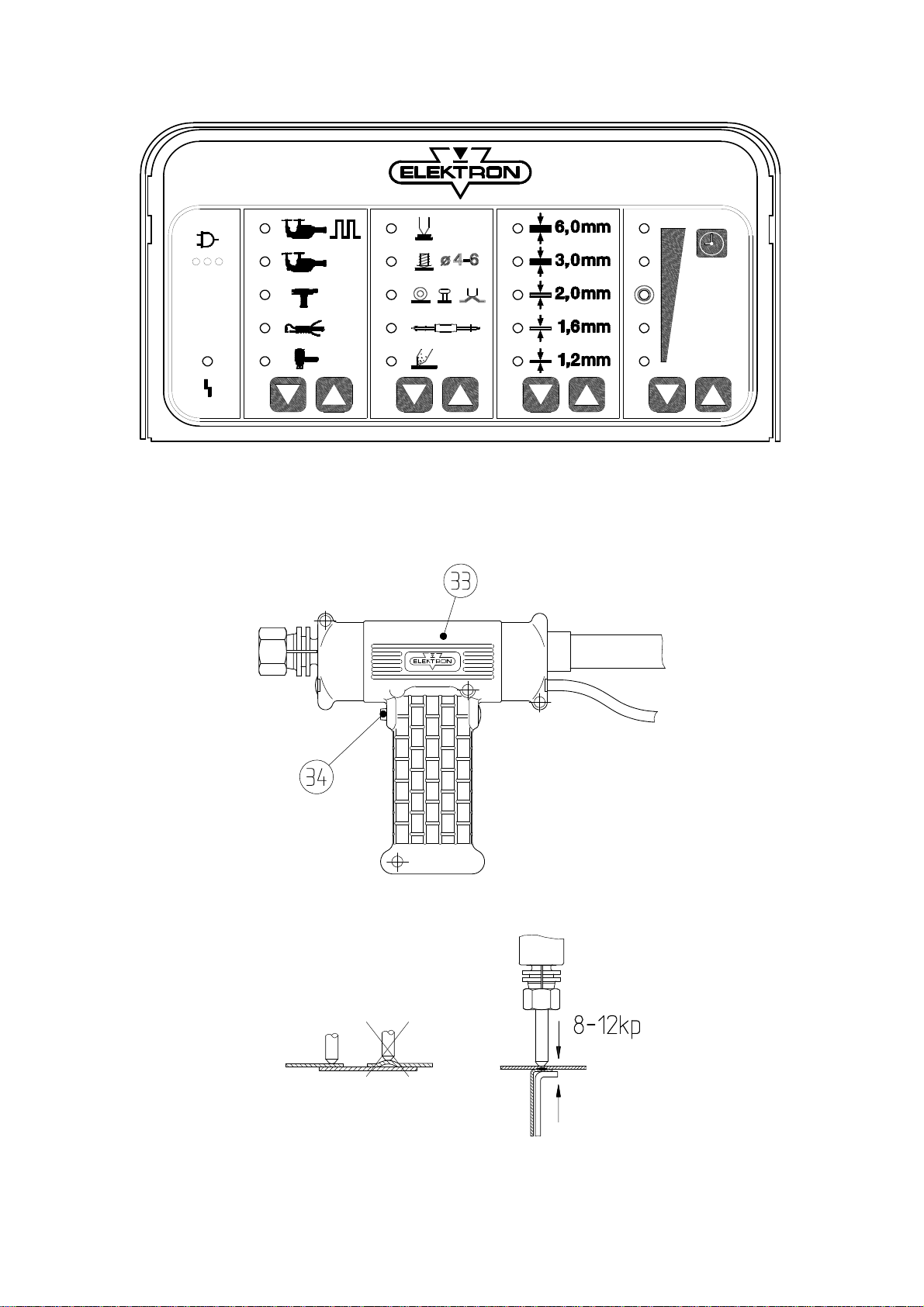
33 Welding gun
34 Button of welding gun
35 Grounding cable
36 Copper shoe
37 Lever clamp
38 Connection piece

- 17 -
7.0 Operating the welding gun
Preparation:
– Insert the central plug of the welding gun (33) into the
central socket (63) until limit stop. Arrow on the plug pointing
upwards.
– The unit will switch automatically to the “gun” symbol.
– Select the “gun” tool with key AB (uncoded gun only).
– Tighten the sleeve nut of the central connection by turning
clockwise.
– Operating pressure at the filter pressure reducer min. 8 bar!
– Connect the copper shoe (36) of the grounding cable (35) to
a bare point on the bodywork to be welded. Use lever clamp
(37) provided or a mole wrench.
Before using the lever clamp (37), you have to weld on two
8 mm washers as close to the point of weld as possible, see
section 7.2! In this case, press the copper shoe (36) of the
grounding cable (35) firmly onto the metal sheet. This is the
only way to obtain a good current transfer.
Attention!
The copper shoe (36) must always be connected to the metal
sheet below the metal part of the body to be worked on. In
any case avoid current transfer via hinges, door and bonnet
locks, as these might otherwise be damaged!
- 18 -
A B C D E F G H
Table of contents
Other Elektron Welding System manuals

Elektron
Elektron MULTISPOT MI-100control User manual

Elektron
Elektron MULTIMIG 400puls User manual

Elektron
Elektron MULTISPOT MI-90 T User manual

Elektron
Elektron MULTIMIG 200 User manual

Elektron
Elektron MULTISPOT MI-100 User manual

Elektron
Elektron MULTISPOT M20 User manual

Elektron
Elektron MULTISPOT MI-100-3 User manual

Elektron
Elektron KERCOMET 170 User manual
Popular Welding System manuals by other brands


Feider
Feider FPSI140A Original instructions

Shengzao Mechanical & Electrical Equipment
Shengzao Mechanical & Electrical Equipment SZ-1800 operating manual

Helvi
Helvi SPOT CAR ALU 33 operating manual

Telwin
Telwin NORDIKA 1800 instruction manual

ESAB
ESAB ESP-50 instruction manual

Miller
Miller Big Blue 500 Pro owner's manual