Elektror HRD 7 FU 120/22 Product guide

Elektror airsystems gmbh
Hellmuth-Hirth-Strasse 2, D-73760 Ostfildern
Postfach 1252, D-73748 Ostfildern
Telefon +49 711 31973-0
Telefax +49 711 31973-5000
info@elektror.de
www.elektror.de
HRD 7
FU 120
Elektror Hoch-
druckventilatoren
Betriebs- und
Montageanleitung
DE
Elektror High
Pressure Blowers
Operating and
assembly
instructions
EN
HRD 7 FU 120/22 mit wassergekühltem Motor
2
DE
Betriebs- und Montageanleitung HRD 7 FU 120 www.elektror.de
9017534 01.20/06
INHALT
1 ANGABEN ÜBER DIE MASCHINE
2 INFORMATIONEN ÜBER TRANSPORT
UND HANDHABUNG
3 INFORMATIONEN ÜBER DIE INBETRIEBNAHME
4 ANGABEN ZU BETRIEB UND VERWENDUNG
5 ANGABEN ZUR INSTANDHALTUNG
6 SICHERHEITSRELEVANTEINFORMATIONENÜBER
AUSSERBETRIEBNAHME UND ABBAU
7 HAFTUNG UND HAFTUNGSAUSSCHLUSS
8 EINBAUERKLÄRUNG NACH ANHANG II 1 B
9 TECHNISCHE DATEN
10 EXPLOSIONSZEICHNUNG
11 ERSATZTEILLISTE
Diese Betriebs- und Montageanleitung muss dem Bedie-
nungspersonal jederzeit zugänglich sein. Lesen Sie die vor-
liegende Betriebs- und Montageanleitung vor Montage und
Inbetriebnahme des Ventilators sorgfältig durch.
Änderungen vorbehalten. Im Zweifelsfall ist eine Rückspra-
che mit dem Hersteller erforderlich. Diese Unterlage ist urhe-
berrechtlich geschützt. Sie darf ohne unsere ausdrückliche
schriftliche Zustimmung Dritten nicht zugänglich gemacht
werden. Jede Form der Vervielfältigung oder Erfassung und
Speicherung in elektronischer Form ist untersagt.
1 ANGABEN ÜBER DIE MASCHINE
Bitte entnehmen Sie unsere Anschrift dem Deckblatt.
Entnehmen Sie den Gültigkeitsbereich dieser Betriebs- und
Montageanleitung bitte der enthaltenen Einbauerklärung
nach Anhang II 1 B.
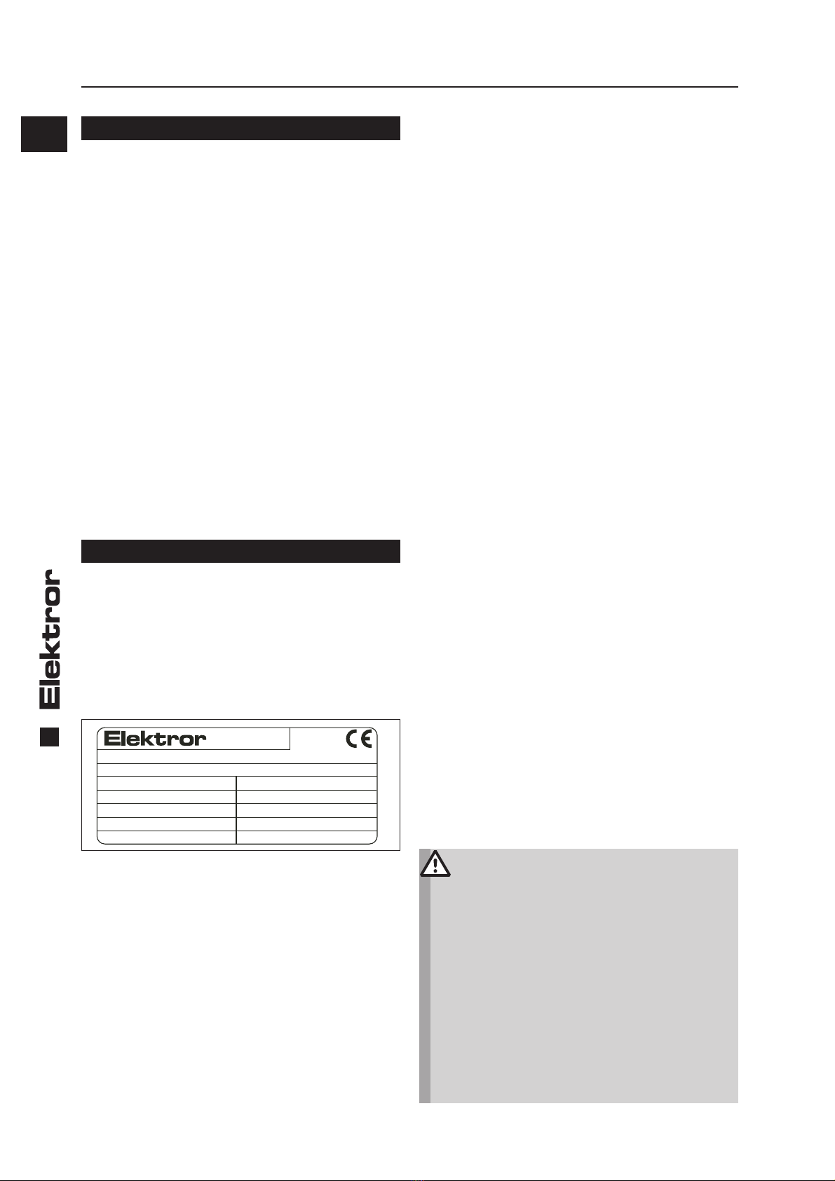
Leistungsschild
Für Anschluss, Wartung und Bestellung von Ersatzteilen sind
ausschließlich die Daten auf dem Leistungsschild maßgeb-
lich. Dem Leistungsschild ist auch die Serien-Nummer des
Gerätes und dessen Herstellungsjahr zu entnehmen.
Typ Nr.
kW cos kW cos
Hz min-1 min-1 Hz
Mot. EN 60034-1 IP W-Kl.F
V V
A A
D-73760 Ostfildern
Germany
1.1 Bestimmungsgemäße Verwendung
Die Ventilatoren eignen sich ausschließlich zum Fördern
von Reinluft.
Der Einsatz für
• aggressive,
• abrasive,
• klebende,
• giftige,
• explosionsfähige oder
• sehr feuchte
Medien ist nicht zulässig.
Die maximale Temperatur des Fördermediums darf bei der
Serienausführung -20°C bis +80°C nicht überschreiten. Die
maximale Umgebungstemperatur darf +40°C nicht über-
schreiten, die minimale -10°C nicht unterschreiten.
Im Fördermedium enthaltene Feststoffe oder Verunreinigun-
gen müssen vor Eintritt in den Ventilator ausgefiltert werden.
Bei Kondensatbildung empfehlen wir eine Kondenswasser-
bohrung an tiefster Stelle im Gehäuse.
Eine Reihen- oder Parallelschaltung von Ventilatoren ist nur
nach Rücksprache mit Elektror möglich.
Der Ventilator ist nicht für die Aufstellung im Freien geeignet.
Der Ventilator ist grundsätzlich für S1-Betrieb (Dauerbetrieb)
ausgelegt.
Davon abweichend sind maximal 30 Schaltungen pro Stun-
de zulässig. In dieser Ausführung eignet sich der Ventilator
nicht für die Aufstellung in oder Förderung von explosionsfä-
higer Atmosphäre.
Umbau und Veränderungen des Ventilators sind nicht zuläs-
sig. Eine Demontage des Laufrades ist ohne Rücksprache
mit der Firma Elektror nicht zulässig!
Elektror-Ventilatoren zeichnen sich durch ein hohes Maß
an Betriebssicherheit aus. Da es sich bei den Ventilatoren
um sehr leistungsfähige Maschinen handelt, sind zur Ver-
meidung von Personenschäden, Beschädigungen von Sa-
chen und der Maschine selbst, folgende Sicherheitshinweise
streng zu beachten.
1.2 Mechanische Gefährdungen
Mechanische Gefährdungen sind an den Elektror-Ventila-
toren dem Stand der Technik und den Anforderungen des
Sicherheits- und Gesundheitsschutzes entsprechend mini-
miert. Um handhabungsbedingte Restrisiken auszuschlie-
ßen, empfehlen wir, in allen Lebensphasen des Gerätes ge-
eignete Schutzausrüstung einzusetzen bzw. zu tragen (bitte
beachten Sie die Hinweise im Folgenden).
1.3 Gefährdung durch Hineinfassen und unerwarteten
Anlauf
Durch rotierende Teile besteht im Inneren des Gerätes im
Betrieb hohes Verletzungsrisiko. Setzen Sie das Gerät vor
dem Öffnen, Hineinfassen oder Einführen von Werkzeugen
in jedem Falle ausser Betrieb und warten Sie den Stillstand
aller bewegten Teile ab. Sichern Sie das Gerät während des
gesamten Zeitraumes zuverlässig gegen Wiederanlauf ab.
Stellen Sie ebenfalls sicher, dass keine Gefährdungssitu-
ation in Folge eines Wiederanlaufes nach einem Stillstand
entsteht, z.B. in Folge einer Energie-Unterbrechung oder
Blockade.
1.4 Gewicht, sicherer Stand
Insbesondere während Transport und Aufstellung bestehen
Gefährdungen durch Umstürzen oder Herabfallen. Siehe 2.1
– Transport und Handhabung, sowie 3.2 – Aufstellen, Mon-
tage.
1.5 Drehzahlen
Warnung!
Zur Vermeidung von Personenschäden darf die auf
dem Motorleistungsschild gestempelte maximale
Drehzahl keinesfalls überschritten werden.
Bei einer Überschreitung droht die Gefahr einer
mechanischen Zerstörung des Ventilators.
Hierbei besteht Verletzungs- und Lebensgefahr!
Jedes Bauteil am Ventilator besitzt individuelle
Eigenfrequenzen. Diese können durch bestimmte
Drehzahlen des Ventilators angeregt werden, was
zu einem möglichen Resonanzbetrieb führt.
Die Ventilatoren sind so konstruiert, dass Reso-
nanzen bei konstanter Betriebsdrehzahl in der
Regel nicht auftreten.
Wird der Ventilator an einem Frequenzumrichter
betrieben, könnte unter Umständen bei einer ge-
änderten Drehzahl eine Anregung erfolgen. Diese
Umstände werden auch durch die kundenindivi-
duelle Einbausituation bzw. durch die lufttechni-

3
DE
www.elektror.de Betriebs- und Montageanleitung HRD 7 FU 120
9017534 01.20/06
sche Anbindung beeinflusst.
Sollten diese Eigenfrequenzen innerhalb des
Drehzahlbereiches des Ventilators liegen, dann
müssen diese durch eine entsprechende Parame-
trierung des Frequenzumrichters ausgeschlossen
werden.
Gerätetyp
Maximalfrequenz
(siehe
Leistungsschild)
Mindestfrequenz
HRD 7 FU-120/22 120 Hz 20 Hz
1.6 Ansaugwirkung
Ventilatoren erzeugen eine starke Saugwirkung.
Warnung!
Am Ansaugstutzen können Gegenstände, Klei-
dungsstücke und auch Haar angesaugt werden.
Verletzungsgefahr!
Während des Betriebs nicht in der Nähe der
Ansaugöffnung aufhalten. Der Ventilator darf nie
mit offenem Ansaugstutzen betrieben werden und
muss daher mit einem Schutzgitter nach DIN EN
ISO 13857 abgedeckt werden.
1.7 Ausblaswirkung
Warnung!
Sehr starke Ausblaswirkung am Ausblasstutzen.
Angesaugte Gegenstände können mit hoher Ge-
schwindigkeit heraus geschleudert werden und
zu Personenschäden führen.
Ventilatoren eignen sich ausschließlich zum För-
dern von Reinluft. Um das Ansaugen von Fremd-
körpern oder Verunreinigungen, die ausgeblasen
werden könnten, zuverlässig zu verhindern,
müssen diese unbedingt vor Eintritt in den Venti-
lator ausgefiltert werden.
Nicht in den Ausblasstutzen hineingreifen!
1.8 Temperatur
Warnung!
Das Ventilatorgehäuse nimmt während des
Betriebs die Temperatur des Fördermediums an.
Wenn diese über +50°C liegt, muss der Ventilator
vom Betreiber vor direktem Berühren geschützt
werden
(Verbrennungsgefahr!).
Besonders bei leistungsstärkeren Typen kann es bei der
Hindurchförderung von der Ansaug- auf die Ausblasseite zur
Erhöhung der Temperatur im geförderten Medium kommen.
Abhängig von den Betriebsbedingungen und der Temperatur
des Fördermediums können die Ausblastemperaturen bei
bis zu +80°C liegen.
1.9 Motorschutzschaltung
Für Frequenzumrichter betriebene Geräte ist der vorhande-
ne Temperaturfühler (PTC-Kaltleiterfühler) oder Temperatur-
wächter (Öffnerkontakt) am Umrichter anzuschließen und
auszuwerten.
1.10 Geräuschentwicklung
Hinweis!
Tragen Sie, ab einem Tagesexpositionspegel von
80 dB(A) und/oder einem Spitzenschalldruckpe-
gel von 135 dB(C), einen Gehörschutz während
des Betriebs.
Bei Nichtbeachtung sind Gehörschäden die
Folge.
Die vom Ventilator abgestrahlten Geräusche sind nicht über
den gesamten Leistungsbereich konstant. Die abgestrahlten
Geräuschpegel entnehmen Sie bitte dem Kapitel 9 Techni-
sche Daten.
In bestimmten ungünstigen Einzelfällen ist eine Schalldäm-
mung erforderlich (Messungen durch den Betreiber werden
empfohlen). Die Schalldämmung muss der Betreiber vor-
nehmen, damit die gesetzlich zugelassenen Höchstwerte an
Arbeitsplätzen in der Umgebung des Ventilators nicht über-
schritten werden.
Schalldämmung jeglicher Art darf zu keiner unzulässigen
Erhöhung der Umgebungstemperatur über max. +40°C am
Antriebsmotor führen.
1.11 Elektrische Gefährdungen
Gefahr!
Gefahr durch elektrischen Strom!
Spannungsführende Bauteile stehen unter Strom
und verursachen tödliche Verletzungen!
Setzen Sie das Gerät vor dem Öffnen, Hineinfas-
sen oder Einführen von Werkzeugen außer Be-
trieb, prüfen die Spannungsfreiheit und sichern
es gegen Wiederanlauf.
2 INFORMATIONEN ÜBER TRANSPORT
UND HANDHABUNG DER MASCHINE
2.1 Transport und Handhabung
• Prüfen Sie vor Montage und Inbetriebnahme alle Teile auf
Transportschäden. Ein beschädigter Ventilator kann ein er-
höhtes Sicherheitsrisiko bedeuten und sollte daher nicht
in Betrieb gesetzt werden.
• Ventilator nicht ungeschützt im Freien lagern
(vor Feuchtigkeit schützen).
• Hebezeug sicher anschlagen. Nur Hebezeuge und Last-
aufnahmeeinrichtungen mit ausreichender Tragfähigkeit
verwenden. Transportwege sichern.
Hinweis!
Die Ringschraube am Motor sollte nicht zum An-
heben des Gesamtventilators verwendet werden.
Diese wird für die Motor(de-)montage verwendet.
2.2 Lagerung
• Stellen Sie sicher, dass der Sauganschluss und der Druck-
anschluss verschlossen sind.
• Den Ventilator
-> möglichst in Originalverpackung
-> in einem geschlossenen Raum
-> trocken, staubfrei und vibrationsfrei
abstellen.
• Lagertemperaturbereich von -10°C bis +60°C
• Nach einer Lagerzeit ab 6 Monaten sind vor dem Ventila-
toreinbau die Ventilatorlager bzw. Motorlager zu überprü-
fen.
• Geräte dürfen maximal 2 Jahre gelagert werden.

4
DE
Betriebs- und Montageanleitung HRD 7 FU 120 www.elektror.de
9017534 01.20/06
3 INFORMATIONEN ÜBER DIE
INBETRIEBNAHME DER MASCHINE
3.1 Grundlegende Hinweise
• Vor der ersten und vor jeder erneuten Inbetriebnahme ist
eine sorgfältige Prüfung auf den ordnungsgemäßen Zustand
des Gerätes vorzunehmen. Geräte, die, z.B. bei Anlieferung
oder Installation, Beschädigungen aufweisen, müssen einer
fachkundigen Überprüfung unterzogen werden.
• Aufstellung, Montage, Betrieb und Instandhaltung dürfen
nur von fach- und sachkundigem Personal durchgeführt wer-
den. Betrieb nach fehlerhafter Montage, Instandhaltung oder
nicht abgestimmtem Austausch von Bauteilen führt zu nicht
bestimmungsgemäßem Gebrauch und zum Verlust der Ge-
währleistung. Das entstehende Risiko trägt der Kunde oder
Betreiber alleine.
3.2 Aufstellen, Montage
• Ventilator vor Witterung geschützt aufstellen. Bei Außen-
aufstellung ist generell ein Witterungsschutz vorzusehen,
der die Vorgaben unter 1.1 Bestimmungsgemäße Verwen-
dung erfüllt und den Ventilator vor Wettereinflüssen schützt.
• Nur mit waagrechter Antriebswelle betreiben.
• Auch im anschließenden Betrieb keinen Schwing- oder
Stoßbelastungen aussetzen.
• Wir empfehlen an den lufttechnischen Anschlüssen die
Verwendung von Kompensatoren.
• Ventilatoren unterliegen hinsichtlich der Schwingungs-
grenzwerte der internationalen ISO 14694.
Die weiteren Spezifikationen entnehmen Sie den nachfol-
genden Informationen.
Messung am Flanschlagerschild,
möglichst in Lagernähe
= Messpunkt
= Messrichtung
Maximal zulässige Schwingungsgeschwindigkeit
(Grenzwerte nach ISO 14694:2003 (E), Kategorie BV-3)
Starr montiert
[mm/s]
Flexibel montiert
[mm/s]
Effektivwert
[rm s]
Effektivwert
[rm s]
Beim Hersteller 2,8 3,5
Im Einbau
Start-up 4,5 6,3
Alarm 7,1 11,8
Shutdown 9,0 12,5
Der dargestellte Ventilator ist lediglich eine Prinzipabbildung.
Aufgrund der Verwendung von Gummipuffern, gilt die Kate-
gorie „Flexibel montiert“.
• Am Einsatzort auf ebenem, festem, ausreichend tragfähi-
gem Untergrund ohne Schwingungsübertragung/-belas-
tung fest verschrauben.
• Nach einer Lagerzeit ab 6 Monaten sind vor dem Ventila-
toreinbau die Ventilatorlager bzw. Motorlager zu überprü-
fen.
• Offene Ansaug- oder Ausblasstutzen mit Schutzgittern
nach DIN EN ISO 13857 abdecken.
• Als Motor wird ein wassergekühlter Elektromotor einge-
setzt.
• Der Motor darf nicht ohne angeschlossenes Kühlgerät/
Wärmetauscher betrieben werden.
• Es gelten die folgenden Bediungungen:
- Die Kühlflüssigkeit muss einen Rostschutz enthalten
- Einlauftemperatur 10°C - 35°C
- Auslauftemperatur 40°C
- Durchfluss 1-6 Liter/Minute
- Druck 4 bar
• Die Angaben auf dem Motor-Leistungsschild und die Infor-
mationen aus der Motorbetriebsanleitung sind zu beach-
ten.
3.3 Elektrischer Anschluss
Hinweis!
Die in diesem Abschnitt beschriebenen Arbeiten
dürfen nur von einer Elektrofachkraft ausge-
führt werden. Anschluss nach dem Schaltbild im
Klemmenkasten und den einschlägigen örtlichen
Bestimmungen vornehmen. Es wird ausdrück-
lich auf die Hinweise im Kapitel „1.5 Drehzahlen“
verwiesen!
Als Antriebsmotor wird ein Motor der Firma Emod eingesetzt
(siehe Betriebsanleitung Motor).
• Für Frequenzumrichter betriebene Geräte ist der vorhan-
dene Temperaturfühler (PTC-Kaltleiterfühler) oder Tempe-
raturwächter (Öffnerkontakt) am Umrichter anzuschließen
und auszuwerten.
• Überprüfung, ob die Netzspannung mit der Angabe auf
dem Leistungsschild übereinstimmt.
• Der Schutzleiteranschluss ist im Klemmenkasten vorhan-
den
Hinweis!
Bei Betrieb des Antriebsmotors mit Frequenzum-
richter ist zusätzlich folgendes zu Beachten:
• Es dürfen nur Motoren am Frequenzumrichter
betrieben werden die mit der Option „/FU“, für
den „Frequenzumrichterbetrieb geeignet“ auf
dem Leistungsschild gekennzeichnet sind, bzw.
die für „Frequenzumrichterbetrieb geeignet“
bestellt und bestätigt wurden.
• Die Versorgungsspannung des Frequenzum-
zumrichters darf ohne Motorfilter maximal 400
V betragen. Bei längeren Leitungen, höheren
Umrichter-Versorgungsspannungen und/oder
Überschreitung der Impulsspannungen (max.
1.000 Vpk für Antriebsmotoren bis 0,75 kW; max.
1.300 Vpk für Antriebsmotoren größer 0,75 kW)
an den Motorklemmen müssen geeignete Maß-
nahmen wie z.B. ein Motorfilter zum Schutz des
Motors installiert werden. Bitte sorgen sie für
ausreichend Platzreserve im Schaltschrank und
berücksichtigen Sie die Vorgaben zu Installation
und Montage in den Betriebsanleitungen des
Frequenzumrichter-/Motorfilterherstellers.
• Die maximale Leitungslänge zwischen Motor
und Frequenzumrichter darf 20 m nicht über-

5
UB
0f
B
verbotener
Bereich
DE
www.elektror.de Betriebs- und Montageanleitung HRD 7 FU 120
9017534 01.20/06
schreiten und muss mit einem geeigneten, abge-
schirmten Kabel, möglichst auf direktem Weg
und ohne weitere Klemm-/Steckverbindungen
ausgeführt werden.
• Das Schirmgeflecht im Anschlusskabel muss
durchgängig und beidseitig d.h. am Frequenzum-
richter und am Motor elektrisch niederohmig mit
dem Erdsystem verbunden sein. Auf der Motor-
seite sind hierzu geeignete EMV-Kabelverschrau-
bungen zu verwenden, die den Kabelschirm am
ganzen Umfang niederohmig kontaktieren.
Weitere Informationen zur EMV-gerechten Installation und
Montage sind den Hinweisen in den Betriebs- und Monta-
geanleitungen des Frequenzumrichterlieferanten zu entneh-
men.
Drehrichtungsprüfung
Ventilator einschalten. Die Laufrichtung des Laufrads muss
mit dem Richtungspfeil auf dem Gehäuse übereinstimmen.
3.4 Sonderverschaltungen und Zusatzklemmen
Für FU-Motoren liegen im Klemmenkasten der Motoren An-
schlusspläne der Lieferung bei.
3.5 Erklärung zur EMV-Richtlinie (2014/30/EU)
Unsere Ventilatoren sind Komponenten die zum Einbau
durch Fachpersonal in andere Maschinen oder Anlagen be-
stimmt, d.h. nicht für den Endanwender vorgesehen sind.
Die Konformität der Endanlage/Maschine mit der EMV-Richt-
linie muss vom Hersteller der Endanlage/Maschine sicherge-
stellt / bestätigt werden.
Ventilatoren bei Netzbetrieb:
Bei Netzbetrieb an sinusförmiger Wechselspannung erfüllen
die in den Geräten eingebaute Asynchronmotoren mit Käfig-
läufer die Anforderungen an die EG-Richtlinie „Elektromag-
netische Verträglichkeit“ 2014/30/EU unter Berücksichtigung
der Normen EN 61000-6-4 (Störaussendung Industrie)
EN 61000-6-3 (Störaussendung Wohnbereich).
Ventilatoren bei Frequenzumrichterbetrieb (FU):
Vor der Inbetriebnahme und beim Betrieb der Geräte am
Frequenzumrichter (sofern dafür geeigent) müssen zur
Erreichung der Anforderungen der EG-Richtlinie „Elektro-
magnetische Verträglichkeit“ 2014/30/EU unbedingt die
EMV-Hinweise des Frequenzumrichterherstellers und die
Angaben in der Elektror- Betriebs- und Montageanleitung
beachtet werden.
Wird das Gerät zusammen mit einem Elektror-Schaltschrank-
Frequenzumrichterpaket ausgeliefert, ist unter Beachtung
der oben genannten EMV-Hinweise die Einhaltung der EN
61800-3 Kategorie C2 (Industriebereich) möglich.
Warnung!
In einer Wohnumgebung kann dieses Produkt
hochfrequente Störungen verursachen, die Ent-
störmaßnahmen erforderlich machen können.
Vor der Inbetriebnahme ist in jedem Fall ein CE-Konformi-
tätsbewertungsverfahren mit den zutreffenden Normen und
Richtlinien durchzuführen.
4 ANGABEN ZU BETRIEB UND
VERWENDUNG
4.1 Grundlegende Hinweise
Bitte beachten Sie die unter 1.1 beschriebenen Hinweise zur
bestimmungsgemäßen Verwendung, sowie die unter 1.2 bis
1.11 beschriebenen Sicherheitshinweise.
Wenn im Betrieb der Bemessungsstrom des Antriebsmotors
überschritten wird, prüfen Sie, ob Netzspannung und -fre-
quenz mit den Daten des Gerätes übereinstimmen.
Nach Schutzabschaltungen wie z.B. Auslösen des Motor-
schutzschalters, Ansprechen des PTC-Auswertegerätes bei
Motoren mit Kalteiterfühler oder Schutzabschaltung des
Frequenzumrichters bei FU-Anwendungen ist ein Neustart
des Gerätes erst nach Identifikation und Beseitigung der Stö-
rungsursache zulässig.
Bei Ventilatoren, die nicht über die ganze Kennlinie einsetz-
bar sind (max. Volumenstrom siehe Leistungsschild), kann
bei zu geringem Anlagenwiderstand der Motor überlastet
werden (zu hohe Stromaufnahme). Drosseln Sie den Vo-
lumenstrom in diesem Fall durch eine auf der Druck- oder
Saugseite eingebaute Drosselklappe.
Der Ventilator darf keinen Schwing- oder Stoßbelastungen
ausgesetzt werden.
4.2 Frequenzumrichterbetrieb
Durch den Einsatz eines Frequenzumrichters ist ein großer
Drehzahlstellbereich möglich, wobei nur eine geringe belas-
tungsabhängige Drehzahldifferenz zwischen Leerlauf und
max. Belastung der Ventilatoren und Seitenkanalverdichter
auftritt.
Für den störungsfreien Betrieb der Ventilatoren ist es
wichtig, dass der Umrichter folgende Forderungen er-
füllt:
• Umrichterleistung gleich oder größer Motorleistung *)
• Umrichterstrom gleich oder größer Motorstrom *)
• Ausgangsspannung des Umrichters gleich der
Motorbemessungsspannung
• Versorgungsspannung max. 480V inklusive 5%
Spannungstoleranz
• Die Pulsfrequenz des Umrichters sollte 8 kHz betragen,
da eine geringere Pulsfrequenz starke Motorgeräusche
erzeugt
•Die Werte zu den Maximal-/Mindestfrequenzen stehen
unter 1.5.
• Der Umrichter muss einen Anschluss für Temperatur-
fühler (PTC-Kaltleiterfühler) oder einen Temperaturwäch-
ter (Öffnerkontakt) haben
*) Werte siehe Leistungsschild
Der Motor kann in Dreieck- oder Sternschaltung, je nach
Eingangsspannung des Umrichters betrieben werden.
Unbedingt ist folgende U/f-Zuordnung am Umrichter
einzustellen.
fBund UB= siehe Leistungsschild
Hochlauf- / Ablaufzeiten
Für die jeweiligen Ventilatortypen (siehe Typenschild) gelten
die nachfolgenden Zeiten:
Gerät Hochlaufzeit [s] Ablaufzeit [s]
HRD 7 FU-120/22 30 60

6
DE
Betriebs- und Montageanleitung HRD 7 FU 120 www.elektror.de
9017534 01.20/06
Innerhalb der Hoch- und Ablaufzeiten muss ein gleichmäßi-
ger Hoch-und Ablauf gewährleistet sein.
Im laufenden Betrieb dürfen keine Drehzahländerungen
auftreten, die die Drehzahländerung beim Hoch- und Ablauf
überschreiten.
Bei Nichtbeachtung steigt der Motorstrom überproportional
an und der Antriebsmotor kommt nicht auf Bemessungsdreh-
zahl.
Warnung!
Zur Vermeidung von Personenschäden bzw. einer
Zerstörung des Ventilators und einer Motorüber-
lastung darf keinesfalls am Umrichter eine höhere
Frequenz (Drehzahl) eingestellt werden, als die
Frequenz (fB), welche auf dem Leistungsschild
angegeben ist. Die Temperaturfühler sind zum
Schutz des Antriebsmotors an den entsprechen-
den Umrichtereingängen anzuschließen.
Die vom Lieferanten des Frequenzumrichters in
den jeweiligen Bedienungs- oder Applikations-
handbüchern beschriebenen Installations- und
Sicherheitshinweise sind unbedingt einzuhalten,
um einen sicheren und störungsfreien Betrieb zu
gewährleisten.
Schutz durch Fehlerstrom-Schutzschalter
(FI-Schutzschalter):
Die aktuellen IGBT-Frequenzumrichter verursachen prinzip-
bedingt Ableitströme >=3,5 mA. Diese Ableitströme können
zu Fehlauslösungen in Anlagen führen, die über einen 30
mA-FI-Schutzschalter abgesichert sind.
Im Fehlerfall können Fehlerströme auch als Gleichstrom
über den Schutzleiter abfließen. Sofern ein Schutz durch
FI-Schutzschalter auf der Versorgungsseite erforderlich ist,
muss unbedingt ein allstromsensitiver (Typ B) FI-Schutz-
schalter verwendet werden. Der Einsatz eines falschen FI-
Schutzschalters anders als Typ B kann im Fehlerfall zu Tod
oder schweren Verletzungen führen.
Zur Erfüllung der Norm EN 61800-5-1 muss die Schutzlei-
terverbindung doppelt, über getrennte Klemmen ausgeführt
oder einen Schutzleiterquerschnitt mit mindestens 10 mm²
Cu ausgeführt werden.
Betrieb und Anschluss an öffentlichen Versorgungs-
netzen:
siehe 3.4
5 ANGABEN ZUR INSTANDHALTUNG
Verschleißteile unterliegen den empfohlenen Instandhal-
tungsintervallen (siehe 5.1 und 5.2). Die Lebensdauer von
Verschleißteilen (Kugellager und Filter) ist abhängig von den
Betriebsstunden, der Belastung und sonstigen Einflüssen
wie Temperatur usw.
Dabei ist zusätzlich zur Betriebsanleitung des jeweiligen Ge-
rätes sowie den Vorschriften und Empfehlungen der gesam-
ten Anlage folgendes zu beachten:
Sofortige Inspektion und Wartung:
Bei Auftreten von Vibrationen und Schwingungen, vermin-
derter Luftleistung.
Hinweis!
Reparaturen dürfen nur vom Hersteller ausge-
führt werden. Bei Reparaturen; Veränderungen
oder Austausch von Bauteilen durch Dritte über-
nehmen wir keine Haftung.
5.1 Kugellager
Hinweis!
Je nach Gerätetyp sind die Kugellager nachzu-
schmieren.
Entnehmen Sie weitere Angaben der Zulieferdo-
kumentation des Motors und der Nachschmier-
einrichtung.
Hinweis!
Die Kugellager bei der Instandhaltung und vor
jeder Wiederinbetriebnahme prüfen.
Der Betrieb ist nur mit einwandfreien Kugellagern
zulässig!
Hinweis!
Bei häufigem An- und Abfahren ist ein vorzeiti-
ger Austausch der Lager erforderlich. Es liegt im
Sicherheitsermessen des Wartungs- und Instand-
haltungspersonal, den Zeitpunkt für den Aus-
tausch der Lager eigenverantwortlich festzulegen.
Geräte Mindestlebensdauer der
Kugellager
waagerechte Motorwelle
HRD 7 FU-120/22 20.000 Stunden
Empfehlung des Kugellagerwechsels
- Vor Erreichen der Mindestlebensdauer
- Spätestens 20 Monate nach Auslieferung
- Nach 6 Monaten Lagerzeit prüfen, bei Bedarf wechseln
Der Ventilator wird mit einem Motor der Firma Emod betrie-
ben. Weitere Angaben entnehmen Sie bitte dem Motor-Ty-
penschild oder den beiligenden Zusatzbetriebsanleitungen.
Bei Dauerbetrieb/Dauereinsatz von 24 h täglich sollten die
in der Tabelle genannten Betriebszeiten nicht überschritten
werden.
Nach einer Lagerzeit ab 6 Monaten sind vor dem Ventila-
toreinbau die Ventilatorlager bzw. Motorlager zu überprüfen.
Weitere Informationen zur Demontage bzw. Montage des
Ventilators erhalten Sie auf Rückfrage von unserem Custo-
mer Support.
5.2 Reinigung
Durch rotierende Teile besteht im Inneren des Gerätes im
Betrieb hohes Verletzungsrisiko. Setzen Sie das Gerät vor
dem Öffnen, Hineinfassen oder Einführen von Werkzeugen
in jedem Falle außer Betrieb und warten Sie den Stillstand
aller bewegten Teile ab. Sichern Sie das Gerät während des
gesamten Zeitraumes zuverlässig gegen Wiederanlauf ab.
Stellen Sie ebenfalls sicher, dass keine Gefährdungssitu-
ation in Folge eines Wiederanlaufes nach einem Stillstand
entsteht, z.B. in Folge einer Energie-Unterbrechung oder
Blockade.
Reinigung oder Wartung dürfen zu keinen Beschädigungen
oder Veränderungen am Gerät und seinen Bestandteilen
führen, die Sicherheits- oder Gesundheitsschutz beeinträch-
tigen, und dürfen z. B. den Wuchtzustand des Laufrades
nicht verschlechtern.
Stellen Sie vor Wiederinbetriebnahme des Ventilators sicher,
das alle Werkzeuge oder sonstigen Fremdkörper aus dem
Geräteinneren entfernt wurden und alle Deckel und Schutz-
gitter wieder ordnungsgemäß montiert sind.

7
DE
www.elektror.de Betriebs- und Montageanleitung HRD 7 FU 120
9017534 01.20/06
6 SICHERHEITSRELEVANTE
INFORMATIONEN ÜBER
AUSSERBETRIEBNAHME UND ABBAU
Das Trennen aller elektrischen Verbindungen und aller wei-
teren elektrotechnischen Maßnahmen in Verbindung mit der
Ausserbetriebnahme darf nur von einer Elektrofachkraft aus-
führt werden.
Der Abbau ist erst zulässig, wenn alle rotierenden Teile den
Stillstand erreicht haben und ein Wiederanlauf nicht mehr
möglich ist.
Zum Abbau und Abtransport müssen die Vorgaben aus 2.1
Transport und Handhabung eingehalten werden.
Die Entsorgung muss fachgerecht durchgeführt werden.
7 HAFTUNG UND HAFTUNGSAUS-
SCHLUSS
Die Verantwortung für die bestimmungsgemäße Verwen-
dung des Gerätes trägt der Betreiber.
Die Fa. Elektror lehnt jede Haftung für nicht bestimmungsge-
mäßen Gebrauch ihrer Geräte und Komponenten ab.
Dies gilt insbesondere auch für besondere Verwendungen
und Einsatzbedingungen, die nicht ausdrücklich mit der Fa.
Elektror abgestimmt wurden.
Elektror lehnt zudem jede Haftung ab für Veränderungen
oder Umbauten am gelieferten Gerät oder Zubehör.
Ebenso haftet die Fa. Elektror nicht für unsachgemäße, ver-
spätete, nicht durchgeführte oder nicht von Elektror-Fach-
personal ausgeführte Wartungsarbeiten und Reparaturen
und deren möglichen Folgen.

8
DE
Betriebs- und Montageanleitung HRD 7 FU 120 www.elektror.de
9017534 01.20/06
Hiermit erklärt die
Elektror airsystems gmbh
Hellmuth-Hirth-Strasse 2
D-73760 Ostfildern
als Hersteller, dass das Produkt, auf das sich diese Erklärung bezieht, den unten folgenden grundlegenden Anforderungen der
Maschinenrichtlinie (2006/42/EG) entspricht.
Beschreibung der unvollständigen Maschine:
Hochdruck-Ventilator HRD 7 FU-120/22
Serien-Nummer und Baujahr sind dem Typenschild und dem zugehörenden Lieferschein zu entnehmen.
Beschreibung der grundlegenden Anforderungen der Maschinenrichtlinie (2006/42/EG), denen die unvollständige
Maschine entspricht:
Maschinenrichtlinie (2006/42/EG): Anhang I, Artikel 1.1.2, 1.1.3, 1.1.5, 1.3.2, 1.3.3, 1.3.4, 1.3.7, 1.5.1, 1.6.1, 1.7.1, 1.7.
Richtlinie über die elektromagnetische Verträglichkeit (2014/30/EU)
Richtlinie zur umweltgerechten Gestaltung energieverbrauchsrelevanter Produkte (2009/125/EG)
Die aufgeführte unvollständige Maschine erfüllt weiterhin die Schutzziele der Niederspannungsrichtlinie (2014/35/EU) gemäß
Anhang I, Nr. 1.5.1 der Maschinenrichtlinie.
Die Inbetriebnahme der unvollständigen Maschine ist so lange untersagt, bis festgestellt wurde, dass die Maschine, in die die
unvollständige Maschine eingebaut werden soll, den Bestimmungen der Maschinenrichtlinie (2006/42/EG) entspricht.
Die folgenden harmonisierten Normen wurden angewandt:
DIN EN ISO 12100 2011 Sicherheit von Maschinen, allgemeine Gestaltungsleitsätze,
Risikobeurteilung und Risikominimierung
DIN EN 60034-1 2011 Drehende elektrische Maschinen,
Teil 1: Bemessung und Betriebsverhalten
DIN EN 60034-5 2007 Drehende elektrische Maschinen,
Teil 5: Schutzarten aufgrund der Gesamtkonstruktion von drehenden
elektrischen Maschinen (IP-Code) – Einteilung
DIN EN 60204-1 2019 Sicherheit von Maschinen – Elektrische Ausrüstung von Maschinen,
Teil 1: Allgemeine Anforderungen
DIN EN 60664-1 2008 Isolationskoordination für elektrische Betriebsmittel in Niederspannungsanlagen,
Teil 1: Grundsätze, Anforderungen und Prüfungen
Die Elektror airsystems gmbh als Hersteller verpflichtet sich, die speziellen Unterlagen zu dieser unvollständigen Maschine
einzelstaatlichen Stellen auf Verlangen elektronisch oder in Papier-Form zu übermitteln. Die zu dieser unvollständigen Maschine
gehörenden speziellen technischen Unterlagen nach Anhang VII Teil B wurden erstellt.
Dokumentationsbevollmächtigter ist Herr Kevin Kargar, Tel. +49 711 31973-1179.
Kreher (Geschäftsführer)
Ostfildern, 17.01.2020
9 TECHNISCHE DATEN
Modell
Volumen-
strom
Gesamt-
druckdiffe-
renz
max. zul.
Ventilator-
drehzahl
Motordreh-
zahl Spannung Frequenz Stromauf-
nahme
Motorleis-
tung Gewicht
Schall-
druckpegel
min/max *1)
[m³/min] [Pa] [min-1] [min-1] [V] [Hz] [A] [kW] [kg] [db A]
HRD 7 FU
-120/22 45,0 18.500 7.200 7.200
siehe
Motorbe-
triebsan-
leitung
siehe
Motorbe-
triebsan-
leitung
siehe
Motorbe-
triebsan-
leitung
siehe
Motorbe-
triebsan-
leitung
137 101/106
*1) min. Wert / max. Wert der Kennlinie
8 EINBAUERKLÄRUNG NACH ANHANG II 1 B
KONFORMITÄTSERKLÄRUNG NACH EVPG § 4 ABS. 1

9
DE
www.elektror.de Betriebs- und Montageanleitung HRD 7 FU 120
9017534 01.20/06

10
EN
Operating and assembly instructions HRD 7 FU 120 www.elektror.com
9017534 01.20/06
CONTENTS
1 MACHINE SPECIFICATIONS
2 INFORMATION ON TRANSPORTATION AND
HANDLING
3 INFORMATION ON PUTTING INTO SERVICE
4 INSTRUCTIONS FOR OPERATION AND USE
5 INSTRUCTIONS FOR MAINTENANCE
6 SAFETY RELATED INFORMATION ON
TAKING OUT OF OPERATION AND REMOVAL
7 LIABILITY AND EXCLUSION OF LIABILITY
8 DECLARATION OF INSTALLATION CONFORMITY
PURSUANT TO ANNEX II 1 B
9 TECHNICAL SPECIFICATIONS
10 BROKEN VIEW DRAWING
11 SPARE PARTS LIST
These operating and assembly instructions should be avail-
able to operating personnel at all times. Read these operat-
ing and assembly instructions carefully before installing and
putting the blower into service.
Subject to change without prior notice. If in any doubt, the
manufacturer should be consulted. This document is protect-
ed by copyright. It must not be disclosed to third parties with-
out our express written consent. Any form of duplication or
recording and storage in electronic equipment is forbidden.
1 MACHINE SPECIFICATIONS
Please refer to the cover sheet for our address.
For details of the scope of these Operating and Assembly
Instructions, please refer to the Declaration of Installation
Conformity pursuant to Annex II 1 B.
Nameplate
The data on the rating plate is applicable to connection,
maintenance and ordering of spare parts. Also refer to the
rating plate for the serial number of the appliance and its year
of manufacture.
Typ Nr.
kW cos kW cos
Hz min-1 min-1 Hz
Mot. EN 60034-1 IP W-Kl.F
V V
A A
D-73760 Ostfildern
Germany
1.1 Designated use
The blowers are designed for delivering clean air only.
Use of the blowers for
• aggressive,
• abrasive,
• sticky,
• toxic,
• explosive or
• very wet
media is not permitted.
The maximum temperature of the medium to be conveyed
must not exceed -20°C to +80°C with the standard model.
The maximum ambient temperature must not exceed +40°C
or drop below -10°C.
Any solid matter or impurities in the medium to be conveyed
must be filtered out before they enter the blower. We recom-
mend a condensed water borehole at the lowest point in the
housing in the event of formation of condensation.
Series connection or parallel connection of fans is only pos-
sible after consultation with Elektror.
The blower is not suitable for installation outdoors. The blow-
er is fundamentally designed for S1 operation (continuous
operation).
However, a maximum of 30 switching operations per hour
are permitted.This model of blower is not designed for install-
ing or conveying in an explosive atmosphere.
Alterations and modifications to the blower are not permitted.
It is not permitted to dismantle the impeller without consulting
Elektror!
Elektror blowers are characterised by a high level of opera-
tional reliability. As the blowers are very powerful machines,
the following safety instructions should be strictly observed
to avoid personal injury as well as damage to property and
the machine itself.
1.2 Mechanical hazards
The mechanical hazards in Elektror blowers have been mini-
mised in accordance with the current state of the art, as well
as the requirements for safety and health protection. To elimi-
nate any further risk on the part of the operator, we recom-
mend that suitable protective gear be used and worn during
all lifecycle phases of the appliance (please refer to the in-
structions below).
1.3 Hazards arising from reaching in and unexpected
start-up
The rotating parts inside the appliance pose a high risk of
injury during operation. Before opening, reaching in or insert-
ing tools into the appliance, always shut it down and wait
until all moving parts come to a standstill. Make sure the ap-
pliance is reliably protected against restarting while work is
in progress.
Also make sure that no hazardous situation can occur as a
consequence of restarting after shutdown, e.g. as a result of
a power cut or blockage.
1.4 Weight and stability
Beware of falling hazards during transportation and installa-
tion in particular. Refer to 2.1 – Transportation and handling,
as well as 3.2 – Installation and assembly.
1.5 Speeds
Warning!
The maximum speed stamped on the motor
rating plate must never be exceeded in order to
prevent personal injury.
The blower is at risk of mechanical damage if the
speed is exceeded.This can cause serious injury
or death!
Each component on the blower has unique natu-
ral frequencies. These can be induced by certain
blower speeds, which may result in resonance
mode. The blowers are designed in such a way
that resonance does not generally occur at a
constant operating speed. This may be induced
in certain circumstances when the speed is
changed if the blower is operated on a frequency
converter. These circumstances are also influ-
enced by the customer’s individual installation
situation or ventilation connection.
These natural frequencies must be excluded by
parametrising the frequency converter according-
ly should they be present within the speed range
of the blower.

11
EN
Operating and assembly instructions HRD 7 FU 120www.elektror.com
9017534 01.20/06
Blower type
Maximum
frequency (see
rating plate)
Minimum fre-
quency
HRD 7 FU-120/22 120 Hz 20 Hz
1.6 Suction effect
The blowers produce a powerful suction effect.
Warning!
Objects, items of clothing and also hair can be
sucked into the intake port. Risk of injury!
Do not stand near the intake opening during op-
eration. The blower must not under any circum-
stances be operated with the intake port open,
and should, therefore, be covered with a wire
guard in conformity with DIN EN ISO 13857
1.7 Blowing effect
Warning!
The blowing effect is very powerful on the ex-
haust side. Sucked in objects may be ejected at
very high speed (danger of injury).
The blowers are designed for delivery of clean
air only. To reliably prevent the sucking-in of
foreign objects or contaminants, which might be
discharged, these objects have to be removed be-
fore entering into the blower by installing a filter.
Do not reach into the exhaust.
1.8 Temperature
Warning!
The blower housing assumes the temperature
of the conveyed medium during operation. If the
temperature of the conveyed medium is above
+50°C, the blower must be protected against
direct contact by the operator
(risk of burn injury).
There may be an increase in the temperature of the medi-
um to be conveyed, particularly with higher pressure mod-
els, when conveying the medium from the air intake side to
the discharge side. The discharge temperatures can rise to
+80°C depending on the operating conditions and tempera-
ture of the medium to be conveyed.
1.9 Motor circuit breaker
For devices operated with a frequency converter, the exist-
ing temperature sensor (PTC resistor sensor) or temperature
gauge (break contact) should be connected and analysed on
the converter.
1.10 Noise emission
Note!
Wear hearing protection during operation at a
daily exposure level of 80 dB(A) and above, and/
or a peak sound pressure level of 135 dB(C) and
above.
Failure to do so may cause hearing damage.
The noise generated by a blower is not constant throughout
the performance range. For details of noise emission levels,
please refer to the chapter 9 “Technical Specifications”.
In some cases, sound insulation may be necessary (it is rec-
ommended that emission levels be measured by the opera-
tor). Sound insulation must be provided by the operator to
avoid exceeding the statutory maximum levels at the work-
place and in the immediate vicinity of the blower.
No sound insulation of any kind whatsoever should cause
the ambient temperature to exceed +40°C at the drive motor
(this is not permissible).
1.11 Electrical hazards
Danger!
Danger from electric current!
Live components carry current and cause fatal
injuries!
Deactivate the device before opening it, reaching
into it or inserting tools into it; check that compo-
nents are not live and secure it against reactiva-
tion.
2 INFORMATION ON TRANSPORTATION
AND HANDLING OF THE MACHINE
2.1 Transportation and handling
• Before installation and putting into service, check all parts
for transit damage. A damaged blower is a potential safety
hazard and, therefore, should not be put into service.
• Do not leave the blower unprotected in the open
(protect against ingress of moisture).
• Attach hoisting gear securely. Only use hoists and load
suspension devices with sufficient load-carrying capacity.
Secure the route of transportation.
Note!
The eye bolt on the motor should not be used to
lift the whole blower. This is used for (dis-)assem-
bling of the motor.
2.2 Storage
• Ensure that the air intake connection and pressure connec-
tion are closed.
• Store the blower
-> in its original packaging if possible
-> in a closed room
-> in a dry, dust-free and vibration-free area.
• Storage temperature range from -10°C to +60°C
• After a storage period of 6 months, the blower bearings and
motor bearings should be checked before they are mounted
in the blower.
• Devices may be stored for a maximum of 2 years.

12
EN
Operating and assembly instructions HRD 7 FU 120 www.elektror.com
9017534 01.20/06
3 INFORMATION ON COMMISSIONING
THE MACHINE
3.1 Basic information
• Prior to the first start-up and before any other start-up, the
proper operating status of the unit must be inspected. Units
that, for example, are found to be defective upon delivery
or during installation, must be examined by qualified techni-
cians.
• Installation, assembly and operation must only be performed
by properly trained and qualified specialists. Operation fol-
lowing incorrect installation, maintenance or unapproved
replacement of components constitutes non-designated use
and renders the warranty void. The resultant risk shall be
borne solely by the customer or owner.
3.2 Installation and assembly
• Protect the blower from the weather when it is being in-
stalled. For outdoor use, protection from the weather must
generally be provided that fulfils the requirements listed in
1.1 Intended Use and protects the blower from the influ-
ences of the weather.
• Only operate with a horizontal drive shaft.
• Do not subject to any vibration stress or impact force either
during the subsequent operation.
• We recommend the use of expansion joints on ventilation
connections.
• Blowers are subject to international ISO 14694 with regard
to vibration limits.
Further specifications can be found in the following informa-
tion:
Measurement on the flange bearing shield,
as close as possible to the bearing
= Measuring point
= Measuring
direction
Maximum permissible vibration speed
(Limit values according to ISO 14694:2003 (E),
category BV-3)
Rigidly mounted
[mm/s]
Flexibly mounted
[mm/s]
Effective value
[rm s]
Effective value
[rm s]
At the
manufacturer‘s 2,8 3,5
At installation
Start-up 4,5 6,3
Alarm 7,1 11,8
Shut-down 9,0 12,5
The blower shown is only a principle figure.
The category “flexibly mounted” applies because of the use
of rubber pads.
• Securely screw the device to a firm and level subsurface
at the place of operation with sufficient load-bearing capac-
ity and no vibration transmission/stress.
• After a storage period of 6 months, the blower bearings and
motor bearings should be checked before they are mount-
ed in the blower.
• Cover the open air intake and discharge with protective
grilles according to DIN EN ISO 13857.
• As drive motor a water-cooled electric motor is engaged.
• The motor must not be operated without installed cooling
unit / heat exchanger.
• The following conditions need to be observed:
- The cooling liquid must contain a rustproofing additives
- Inlet temperature 10°C - 35°C
- Outlet temperature 40°C
- Flow 1-6 liters/minute
- Pressure 4 bar
• The details on the motor rating plate and the information
from the engine operating manual must be observed.
3.3 Electrical connection
Note!
The work described in this section may only be
performed by a qualified electrician. Connect the
appliance as per the circuit diagram in the termi-
nal box and in accordance with the relevant local
requirements.
We refer specially to the instructions in chapter
“1.5 Speeds”!
As drive motor a motor of the company Emod is engaged
(see instruction manual of the motor).
• For devices operated with a frequency converter, the exist-
ing temperature sensor (PTC resistor sensor) or tempera-
ture gauge (break contact) should be connected and ana-
lysed on the converter.
• Check whether the mains voltage corresponds with the in-
formation on the rating plate.
• The protective earth conductor is in the terminal box.
Note!
For operation of the drive motor with a frequency
converter, the following points should also be
noted:
• Motors may only be operated on a frequency
converter if they have “/FU” (which denotes
“frequency converter compatible”) marked on
the rating plate, or if they have been ordered as
“frequency converter compatible” motors and
confirmed.
• The maximum supply voltage of the frequency
converter is 400 V without a motor filter. If longer
wires and higher converter supply voltages are
used and/or the max. pulse voltage (max. 1000
Vpk for drive motors up to 0.75 kW, maximum
1300 Vpk for drive motors larger than 0.75 kW) at
the motor terminals is exceeded, suitable precau-
tions, e.g. a motor filter, must be taken to protect
the motor. Please ensure sufficient space in the
control cabinet and consider the requirements
for installation and assembly in the operating
manuals of the frequency converter / motor filter
manufacturer.
• The wire running between the motor and the
frequency converter must not exceed a length of
20 m, configured as a suitable, shielded cable and
laid by as direct a route as possible, without any
additional plug/clamp connections.

13
U
B
0fB
Prohibited
range
EN
Operating and assembly instructions HRD 7 FU 120www.elektror.com
9017534 01.20/06
• The braided screen in the connecting cable
must cover the full length of the cable on both
sides, i.e. be connected to the grounding system
at the frequency converter and to the motor using
a low electrical resistance. For this purpose, suit-
able EMC cable couplings must be used on the
motor side. They must contact the cable shield
around its full circumference and have a low
resistance.
For further information about EMC compliant installation and
assembly, refer to the Operating and Assembly Instructions
issued by the frequency converter manufacturer.
3.4 Special configurations and additional clamps
For FU motors terminal diagrams are supplied with the termi-
nal boxes of the motors.
3.5 Declaration concerning the EMC Directive (2014/30/EU)
Our blowers are components that are designed to be in-
stalled in other machines or systems by qualified personnel,
i.e. not intended for consumers. The manufacturer of the
final system/machine must guarantee/confirm that the final
system/machine complies with the EMC Directive.
Blowers with mains operation:
With mains operation to a sinusoidal AC voltage, the asyn-
chronous motors with a squirrel-cage rotor that are built into
the devices meet the requirements of the EC “Electromag-
netic Compatibility” Directive 2014/30/EU, taking into ac-
count the standards EN 61000-6-4 (Emitted interference in
industrial environments) and EN 61000-6-3 (Emitted interfer-
ence in residential environments).
Blowers with frequency converter operation (FU):
Prior to the start-up and during operation of the device on a
frequency converter (provided that this is suitable) it is es-
sential that the EMC instructions from the frequency convert-
er manufacturer and the information in the Elektror operating
and assembly instructions are observed in order to meet the
requirements of the EC “Electromagnetic Compatibility” Di-
rective 2014/30/EU.
If the device is delivered together with an Elektror switch cab-
inet frequency converter package, it is possible to comply
with the EN61800-3 category C2 (Industrial environments),
taking into consideration the above-mentioned EMC instruc-
tions.
Warning!
This product may cause high-frequency inter-
ference in a residential environment that may
require screening measures.
A CE conformity assessment with the relevant standards and
guidelines must be carried out in all cases before the start-
up.
4 INSTRUCTIONS FOR OPERATION
AND USE
4.1 Basic information
Please observe the notes on designated use in section 1.1,
as well as the safety guidelines in sections 1.2 to 1.14.
If electrical current drops below the rated current of the drive
motor during operation, check to see if the mains voltage and
frequency match the appliance ratings.
After protective shutdowns, e.g. tripping of the motor circuit-
breaker, activation of the PTC evaluation unit by motors with
a PTC resistor sensor, or after a protective shutdown of the
frequency converter during FU applications, the appliance
must not be restarted until the problem has been trouble-
shooted.
If the blower cannot be operated over the whole range of the
characteristic curve, the motor may overload if the system
resistance is too low (excessive current consumption). The
volumetric air flow should be reduced in this case by means
of a throttle valve fitted on the intake or discharge side.
The blower must not be subjected to vibration or impact
loads.
4.2 Frequency converter operation
A frequency converter is used, allowing a wide range of
speed adjustments. There is only a small, load-related dif-
ference in rpm between idle state and the max. load of the
blowers and the lateral channel blower.
To ensure trouble-free operation of blowers it is impor-
tant that the converter meet the following requirements:
• Converter output equal to or greater than motor power
output *)
• Converter current equal to or greater than motor current *)
• Converter output voltage equal to rated motor voltage
• Supply voltage max. 480V, including 5% voltage tolerance
• The pulse frequency of the converter should be 8 kHz,
since a lower pulse frequency can cause very noisy motor
operation.
• The values for the maximum/minimum frequency can be
found at 1.5.
• The converter should have a connection for a tempera-
ture sensor (PTC resistor sensor) or a temperature switch
(normally-closed contact)
*) Refer to the rating plate for data
The motor can be operated in a delta or star-point configura-
tion, depending on the input voltage of the converter.
The following U/f assignments must be configured at
the converter.
fBand UB= refer to rating plate
Run-up/expiry times
The following times apply to the corresponding blower types
(see rating plate):
Blower type Start-up time
[s]
Expiry time
[s]
HRD 7 FU-120/22 30 60
A uniform run-up and expiry must be guaranteed within the
run-up and expiry times.
No speed changes must occur during operation that exceed
the speed change during run-up and expiry.
Failure to observe this information leads to a disproportion-
ate increase in the motor current and the drive motor does
not reach the rated speed.

14
EN
Operating and assembly instructions HRD 7 FU 120 www.elektror.com
9017534 01.20/06
Warning!
A higher frequency (speed) than the frequency
(fB) that is specified on the rating plate must
never be set on the converter in order to avoid
personal injury and/or damage to the blower and
motor overload. The temperature sensors are
connected to the corresponding converter inputs
to protective the drive motor.
It is absolutely essential that you observe the
installation and safety instructions described in
the respective operating or application manuals
provided by the frequency converter suppliers to
guarantee a safe and trouble-free operation.
Protection by residual current circuit breakers
(FI-circuit breakers):
The current IGBT frequency converters inherently produce
leakage currents > =3.5 mA. These leakage currents can
lead to false alarms in systems that are fused using a 30 mA
FI-circuit breaker.
In the event of a fault, residual current can also leak as direct
current via the protective conductor. If protection is required
on the supply side by means of a FI-circuit breaker, it is im-
portant that an FI-circuit breaker is used that is sensitive to
universal current (type B). The use of an incorrect FI-circuit
breaker other than type B can lead to death or serious injury
in the event of a fault.
The protective conductor must be designed to connect twice
via isolated terminals or via a protective conductor cross-
section with a minimum of 10 mm2 Cu to comply with the
EN61800-5-1 standard.
Operation and connection to public supply networks:
See 3.4
5 INSTRUCTIONS FOR MAINTENANCE
Wearing parts are subject to the recommended maintenance
intervals (refer to 5.1 to 5.2). The service life of wearing parts
(ball bearings and filters) depends on the operating hours,
the load and other influences, such as temperature, etc.
This is in addition to the operating instructions of the device
as well as the rules and recommendations of the entire sys-
tem, note the following:
Immediate inspection and maintenance:
The blower must be inspected immediately if vibrations or
reduced air flow are observed.
Note!
Repairs must be carried out by the manufacturer.
We cannot accept any liability for repairs carried
out by third parties.
5.1 Ball bearings
Note!
The ball bearings are to be relubricated depen-
ding on the device type.
Refer to the supplier‘s documentation for the
motor and the relubrication equipment for further
details.
Note!
Check the ball bearings during servicing and
prior to recommissioning.
Operation is only permitted with flawless ball
bearings!
Note!
In the event of frequently starting up and shutting
down, premature replacement of the bearings will
be required. Determining the time for replacing
the bearings is the sole responsibility of the main-
tenance and servicing personnel, who must make
a safety judgement.
Devices Minimum ball bearing service
life
Horizontal motor shaft
HRD 7 FU-120/22 20.000 Hours
Ball bearing change recommendation
- Prior to reaching the minimum service life
- 20 months following delivery at the latest
- Check after 6 months’ storage time; change if necessary
The blower is operated with a drive motor of the company
Emod. For more information, please refer to the nameplate
of the motor or the additional instruction manuals.
The operating hours specified in the table should not be ex-
ceeded during continuous operation/use 24 hours a day.
After a storage period of 6 months, the blower bearings and
motor bearings should be checked before they are mounted
in the blower.
Please contact our Customer Support for further information
about the (dis-) assembly of the blower.
5.2 Cleaning
There is a high risk of injury from the rotating parts on the
inside of the device during operation. Decommission the de-
vice in all cases and wait until all moving parts have stopped
before opening, reaching in or inserting tools into the device.
Secure the device reliably against it being accidentally re-
started during the entire period. Also make sure that no other
dangerous situations can arise when restarting after stand-
ing still, e.g., as a result of a power failure or blockages.
Cleaning or maintenance must not lead to damage or modi-
fications to the device and its components that affect safety
or health protection and, for example, impair the balance of
the impeller.
When starting up the blower, make sure that all tools or other
foreign objects have been removed from inside the device
and that all covers and protective grilles have been attached
correctly.
6 SAFETY RELATED INFORMATION
ON TAKING OUT OF OPERATION AND
REMOVAL
The disconnecting of all electrical connections and all oth-
er electrical engineering work in connection with taking the
blower out of operation must be referred to a qualified electri-
cian.
The blower may only be dismantled after all rotating parts
have come to a standstill and a safeguard has been provided
to prevent restarting.
Dismantling and removal must be performed in accordance
with the guidelines set out in section 2.1, Transportation and
handling.
Dispose of in the appropriate manner.

15
EN
Operating and assembly instructions HRD 7 FU 120www.elektror.com
9017534 01.20/06
7 LIABILITY AND EXCLUSION OF
LIABILITY
The owner shall bear the responsibility for the correct use of
the device.
Elektror shall not accept any liability for any use of its prod-
ucts and components which is contrary to their intended use.
This shall also apply in particular to use in special applica-
tions and under operating conditions that have not been spe-
cifically agreed with Elektror.
Elektror shall not accept any liability for any modifications or
alterations to the device or accessories supplied.
Likewise, Elektror shall not be liable for improper, delayed,
neglected maintenance.
Neither shall it be liable for any cleaning and repair work not
carried out by qualified Elektror specialists, nor for the pos-
sible consequences.

16
EN
Operating and assembly instructions HRD 7 FU 120 www.elektror.com
9017534 01.20/06
The manufacturer,
Elektror airsystems gmbh
Hellmuth-Hirth-Strasse 2
D-73760 Ostfildern
hereby declares that the product to which this declaration refers meets the basic requirements of the Machinery Directive (2006/42/
EC) as set forth below.
Description of incomplete machine:
High Pressure Blower HRD 7 FU-120/22
Serial number and year of manufacture can be found on the nameplate and on the accompanying delivery slip.
Description of the essential requirements of Machinery Directive (2006/42/EC), with which the partially completed
machine complies:
Machinery Directive (2006/42/EC): Annex I, Articles 1.1.2, 1.1.3, 1.1.5, 1.3.2, 1.3.3, 1.3.4, 1.3.7, 1.5.1, 1.6.1, 1.7.1, 1.7.
Electromagnetic Compatibility Directive (2014/30/EU)
Eco-design Directive for Energy-related Products (2009/125/EC)
The partially completed machine described here continues to fulfil the protective regulations of the Low Voltage Directive
(2014/35/EC) according to Annex I, No. 1.5.1 of the Machinery Directive.
The commissioning of the partially completed machine is not permitted until it has been verified that the machine in which the partially
completed machine is to be installed, complies with the provisions of the Machinery Directive (2006/42/EC).
The following harmonised standards have been applied:
DIN EN ISO 12100 2011 Safety of machinery - General principles of design -
Risk assessment and risk reduction
DIN EN 60034-1 2011 Rotating electrical machines,
Part 1: Rating and performance
DIN EN 60034-5 2007 Rotating electrical machines,
Part 5: Degrees of protection provided by the integral
design of rotating electrical machines (IP code) – Classification
DIN EN 60204-1 2019 Safety of machinery – Electrical equipment of machines,
Part 1: General requirements
DIN EN 60664-1 2008 Insulation coordination for equipment within low-voltage systems,
Part 1: Principles, requirements and tests
As manufacturer, Elektror airsystems gmbh undertakes to forward the special technical documentation in respect of the partially
completed machine to national authorities at their request. The special technical documentation in respect of this partially completed
machine according to Appendix VII Part B has been created.
The person responsible for the documentation is Mr Kevin Kargar, Tel. +49 711 31973-1179.
Kreher (Managing Director)
Ostfildern, 17.01.2020
9 TECHNICAL SPECIFICATIONS
Type
Volumetric
flow rate
Total
pressure
difference
Max.
permitted
blower
speed
Motor
speed Voltage Frequency
Power
consump-
tion
Motor
power Weight
Sound
pressure
level
min/max *1)
[m³/min] [Pa] [min-1] [min-1] [V] [Hz] [A] [kW] [kg] [db A]
HRD 7 FU
-120/22 45,0 18.500 7.200 7.200
see motor
operating
instruc-
tions
see motor
operating
instruc-
tions
see motor
operating
instruc-
tions
see motor
operating
instruc-
tions
137 101/106
*1) Min. value / max. value of characteristic curve
8 DECLARATION OF INSTALLATION CONFORMITY PURSUANT TO ANNEX II 1 B
DECLARATION OF CONFORMITY IN ACC. WITH EVPG (ENERGY CONSUMPTION
RELEVANT PRODUCTS ACT).SECTION 4 PARAGRAPH 1

17
EN
Operating and assembly instructions HRD 7 FU 120www.elektror.com
9017534 01.20/06

18
9017534 01.20/06
G
H
9
1
16
13 17
15
23 624
2
3
4
5
7
4
4
8
10 11 12 14 15 18 19 20 21 22
6
6
10 EXPLOSIONSZEICHNUNG FÜR GERÄTE HRD 7 FU 120 / BROKEN VIEW DRAWING FOR DEVICE HRD 7 FU 120

19
9017534 01.20/06
11 ERSATZTEILLISTE FÜR HRD 7 FU 120 / SPARE PART LIST FOR DEVICE HRD 7 FU 120
Hochdruckventilator HRD 7 FU 120/22 High pressure blower HRD 7 FU 120/22
Pos. Benennung Designation
1 Radialwellendichtring Radial shaft seal
2 Motorkonsole Motor console
3 Seitenbügel rechts Lateral frame right
4Unterlegscheiben - große Ausführung - Produkt-
klasse C ISO 7093 C - ST 10 - 100 H
Washer - large version
product class C ISO 7093 C - ST 10 - 100 H
5Sechskantschrauben mit Ganzgewinde
ISO 4017 - M10 x 25
Hexagon head screws with comlete thread
ISO 4017 - M10 x 25
6 Federring Spring washer
7 Sechskantmutter ISO 4032 - M10 Hexagon nuts ISO 4032 - M10
8 Sechskantschraube ISO 4017 - M10 x 45 Hexagon screw ISO 4017 - M10 x 45
9 Motor 132 WK Motor 132 WK
10 Sechskantschraube mit Flansch
DIN 6921 - M6 x 25
Hexagon head screw with flange
DIN 6921 - M6 x 25
11 Sechskantmutter ISO 4032 - M12 Hexagon nut ISO 4032 - M12
12 Federring Spring washer
13 Scheibe Washer
14 Seitenbügel links Laterale frame left
15 Sechskantschraube mit Flansch
DIN 6921 - M6 x 20
Hexagon head screw with flange
DIN 6921 - M6 x 20
16 Ventilatorflansch Blower flange
17 Zylinderkopfschraube DIN 912 - M12 x 50 Cylinder head screw DIN 912 - M12 x 50
18 Ventilatorgehäuse Blower housing
19 Laufrad Impeller
20 Scheibe Washer
21 Wellenmutter YN Shaft nut YN
22 Gehäusedeckel Housing cover
23 Schutzgitter Wire mesh guard
24 Sechskantschraube Hexagon head screw
Bei Bestellung folgendes angeben:
Geräte-Nr. (Leistungsschild) und Geräte-Typ (Leistungsschild)
When ordering please state:
Serial no. (rating plate) and blower type (rating plate)
Gehäusestellungen
Die Gehäusestellung des Ventilators ist für die Bestellung einiger Ersatztei-
le entscheidend. Bestellen Sie Ersatzteile zur Drehrichtung passend.
Housing positions
The position of the blower housing is important for ordering several spare
parts.Order spare parts which match the direction of rotation.
RD 0
(Fl)
RD 270
(El)
RD 90
(Gl)
RD 180
(Hl)
LG 0
(Br)
LG 270
(Ar)
LG 90
(Cr) LG 180
'U

9017534 01.20/06
Für Druckfehler und Irrtum wird nicht gehaftet. | Errors and omissions excepted.
Technische und Konstruktive Änderungen vorbehalten! | Subject to technical and design modifications.
Weitere Informationen zu unseren Produkten finden Sie auch im Internet unter www.elektror.de
Gerne steht Ihnen auch unser Produktmanagement unter der Rufnummer +49 711 31973-1111 zur Verfügung.
You will find further information about our products on the internet at www.elektror.com
Our Product management staffwill be pleased to answer your queries at +49 711 31973-1111.
Hellmuth-Hirth-Strasse 2, D-73760 Ostfildern
Postfach 12 52, D-73748 Ostfildern
+49 711 31973-0
+49 711 31973-5000
support@elektror.de
www.elektror.de
Table of contents
Languages:
Other Elektror Fan manuals


Popular Fan manuals by other brands


Toshiba
Toshiba VN-U00151SY-E owner's manual

Amaircare
Amaircare Airwash MultiPRO BOSS AH2000 CART Operating and maintenance manual

Hinkley
Hinkley SCULPT 903680FMB-LDD instruction manual

NuAire
NuAire MEV-X Installation and Maintenance

LEMAX
LEMAX L760 installation manual

Ebmpapst
Ebmpapst W2E200-DE63-52 operating instructions


