element ergo TITAN t33m Quick setup guide

“'v—r'r-w.
v
*/:'r
‘
t.
_
_
A‘
.
4
_
"h
<l‘v-,_l~.,-,‘.
I
.
I
-
‘
.
—-WA..~‘.HT‘§-WTW_VI
.fflwfi
m“.
I
A
iv
my.
T3AC
TITAN
by
element
ergo
ASSEMBLY
&
USE
INSTRUCTIONS
90.014.01.0252v.D

Make
sure
no
obstacles
are
in
the
desk’s
path.
Make
sure
the
desktop
is
not
touching
any
walls.
A
Make
sure
all
cords
are
appropriate
length
to
accommodate
the
change
in
height.
Pinch
Point
Keep
hands
and
fingers
clear.
Keep
children
away
from
electric
height-adjustable
desks,
control
A
units
and
handsets.
There
is
a
risk
of
iniury
and
electric
shock.
Do
not
sit
or
stand
on
the
desk
frame.
Do
not
crawl
or
lie
under
the
desk
trame.
Do
not
place
any
objects
taller
than
20"
underneath
the
desk.
A
Do
not
open
any
at
the
components
-
the
Legs,
Control
Box,
or
Switch.
There
is
a
danger
of
electric
shock.
0
In
the
event
of
a
power
outage
or
it
the
power
cord
is
unplugged,
a
manual
reset
may
be
necessary
-
see
USE
section.
This
product
is
designed
with
a
duty
cycle
of
lO%
(2
min.
on,
18
min.
off).
A
A
0
0
IUSE
/
LIABILITY—
This
height
adiustable
desk
has
electric
motors
and
is
designed
for
use
in
dry
work
areas
only.
The
desk
height
is
adiustable
so
that
it
can
be
positioned
at
the
most
ergonomically
suitable
height.
Any
other
use
is
at
user's
risk.
Under
no
circumstances
does
the
manufacturer
accept
warranty
claims
or
liability
claims
for
damages
caused
from
improper
use
or
handling
at
the
desk
frame.
IMPORTANT:
Please
read
this
manual
carefully.
If
this
desk
is
sold,
please
provide
this
manual
to
the
buyer.
8
(D
(‘D
i
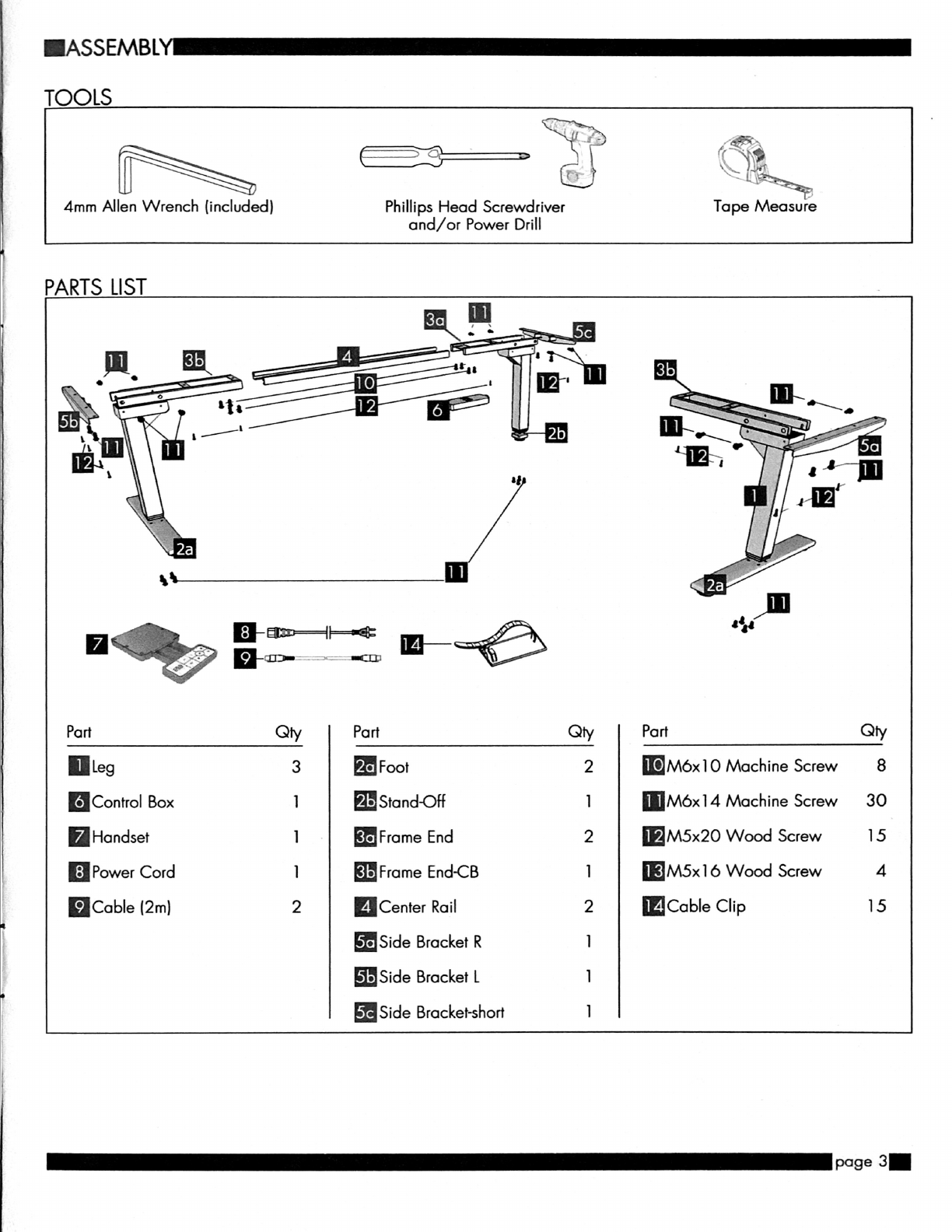
IASSEMBL
TOOLS
Ta
pe
Measure,
Phillips
Head
Screwdriver
and/or
Power
Drill
Qty
Part
2
M6xl
0
Machine
Screw
8
l
M6x14
Machine
Screw
3O
2
M5x2O
Wood
Screw
15
Qty
3
Foot
1
Stand-Off
1
Frame
End
1
Frame
EndCB
2
Center
Rail
Side
Bracket
R
Side
Bracket
L
Side
Bracket-short
1
“Control
Box
Handset
“Power
Cord
nCable
(2m)
1
M5xl
6
Wood
Screw
4
2
Cable
Clip
15
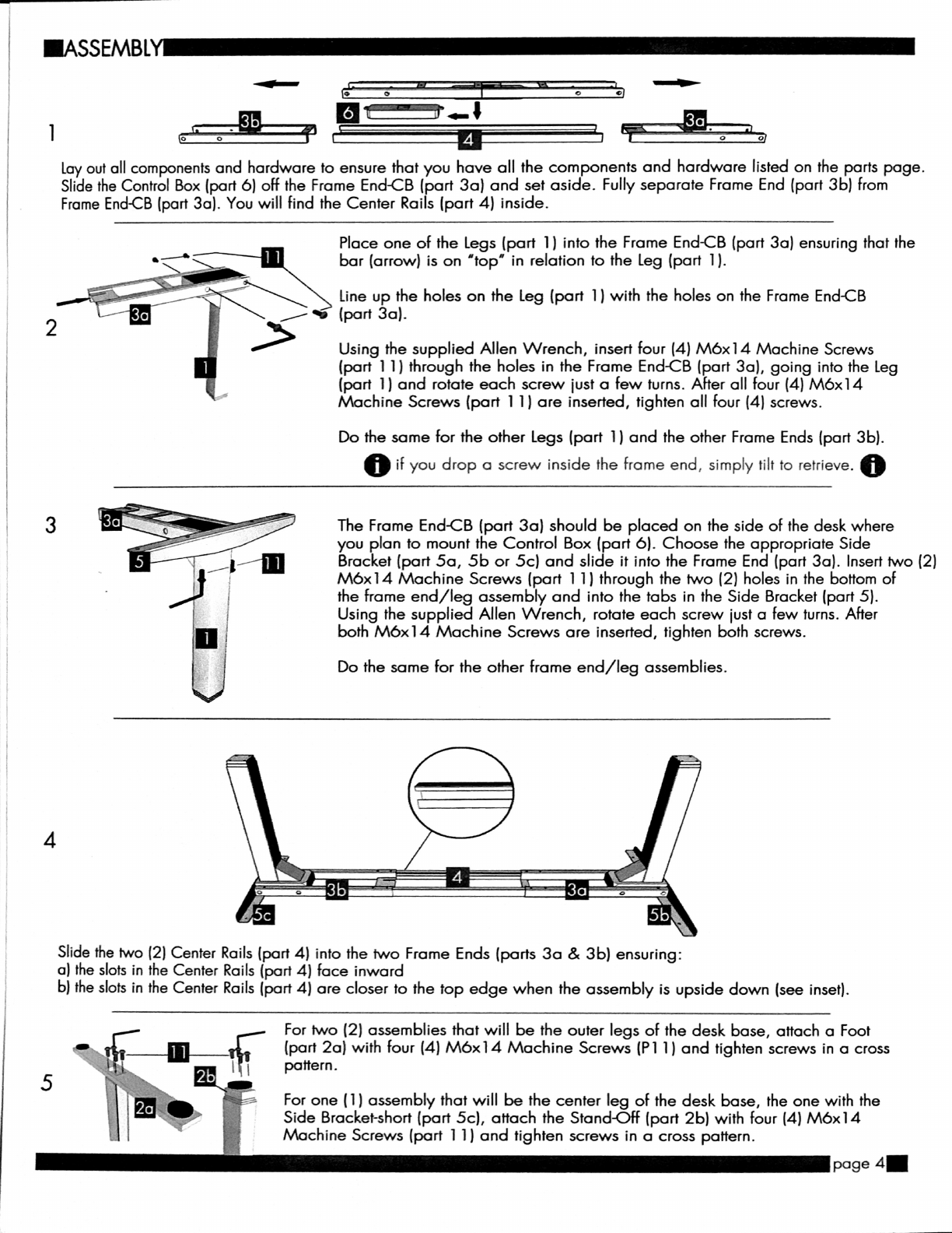
Lay
out
all
components
and
hardware
to
ensure
that
you
have
all
the
components
and
hardware
listed
on
the
parts
page.
Slide
the
Control
Box
(part
6)
OFF
the
Frame
End-CB
(part
30)
and
set
aside.
Fully
separate
Frame
End
(part
3b)
from
Frame
End-CB
(part
30).
You
will
find
the
Center
Rails
(port
4)
inside.
Place
one
of
the
Legs
(part
1)
into
the
Frame
End-CB
(part
30)
ensuring
that
the
bar
(arrow)
is
on
'top'
in
relation
to
the
Leg
(part
1).
’\‘K
Line
up
the
holes
on
the
Leg
(part
1)
with
the
holes
on
the
Frame
End-CB
/
‘0
(port
30).
>
Using
the
supplied
Allen
Wrench,
insert
tour
(4)
be14
Machine
Screws
(part
1
1)
through
the
holes
in
the
Frame
End-CB
(part
30),
going
into
the
Leg
(part
1)
and
rotate
each
screw
just
a
few
turns.
After
all
four
(4)
M6x14
Machine
Screws
(port
1
1)
are
inserted,
tighten
all
(our
(4)
screws.
Do
the
some
for
the
other
Legs
(part
1)
and
the
other
Frame
Ends
(part
3b).
0
it
you
drop
a
screw
inside
the
frame
end,
simply
tilt
to
retrieve.
0
The
Frame
End-CB
(port
30)
should
be
placed
on
the
side
of
the
desk
where
you
plan
to
mount
the
Control
Box
(part
6).
Choose
the
appropriate
Side
Bracket
(part
50,
5b
or
5c)
and
slide
it
into
the
Frame
End
(part
30).
Insert
two
(2)
M6x14
Machine
Screws
(part
1
1)
through
the
two
(2)
holes
in
the
bottom
of
the
home
end/leg
assembly
and
into
the
tabs
in
the
Side
Bracket
(part
5).
Using
the
supplied
Allen
Wrench,
rotate
each
screw
just
a
few
turns.
After
both
M6x14
Machine
Screws
are
inserted,
tighten
both
screws.
Jig/III
!
i
l
LI"
1
t
Do
the
same
for
the
other
frame
end/
leg
assemblies.
Slide
the
two
(2)
Center
Rails
(part
4)
into
the
two
Frame
Ends
(parts
30
&
3b)
ensuring:
a)
the
slots
in
the
Center
Rails (part
4)
face
inward
b)
the
slots
in
the
Center
Rails
(port
4)
are
closer
to
the
top
edge
when
the
assembly
is
upside
down
(see
inset).
For
two
(2)
assemblies
that
will
be
the
outer
legs
at
the
desk
base,
attach
0
Foot
(part
20)
with
tour
(4)
be14
Machine
Screws
(P1
1)
and
tighten
screws
in
a
cross
pattern.
For
one
(1)
assembly
that
will
be
the
center
leg
of
the
desk
base,
the
one
with
the
Side
Bracket-short
(part
5c),
attach
the
Stand-Off
(port
2b)
with
(our
(4)
M6x14
Machine
Screws
(port
1
1)
and
tighten
screws
in
a
cross
pattern.
page
4-
J
.\

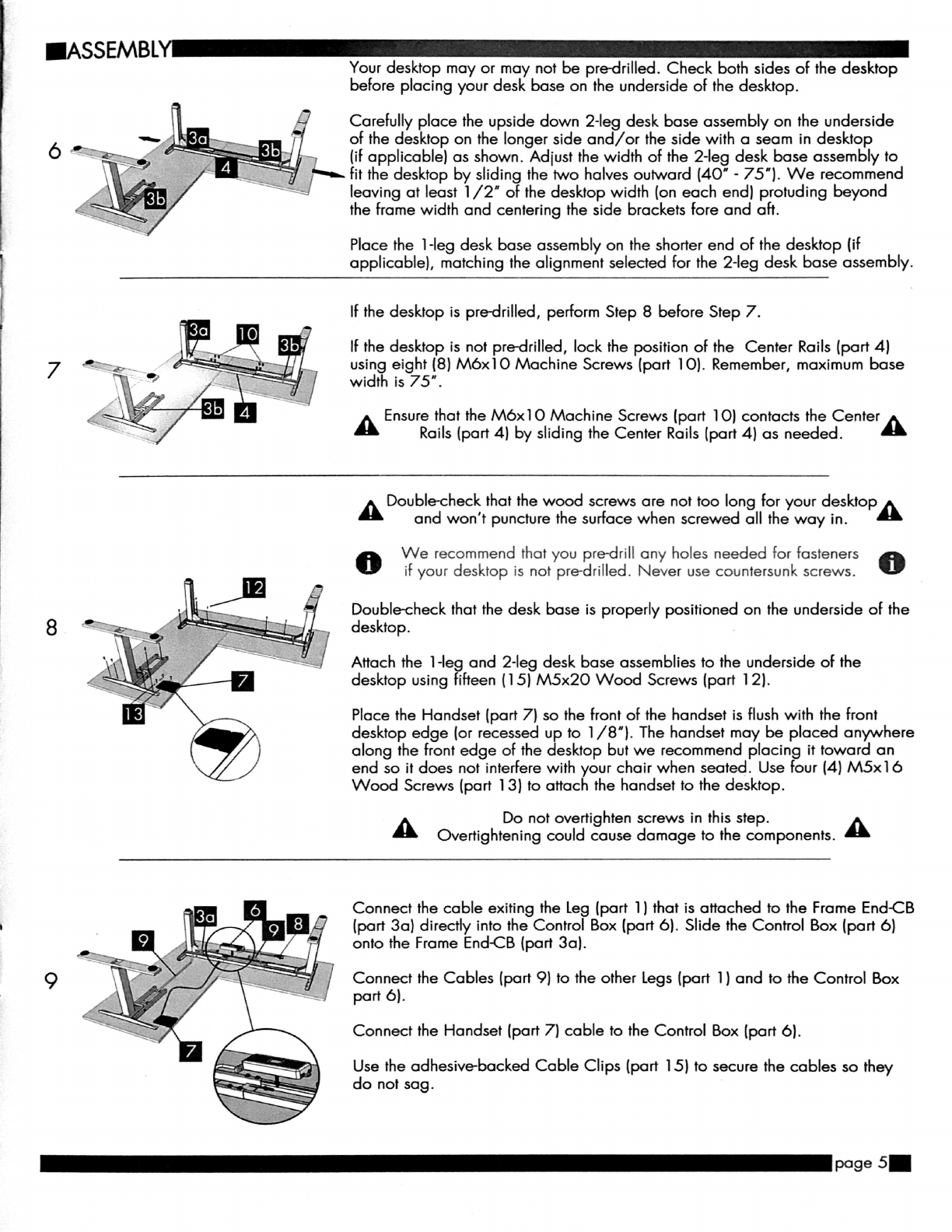
IASSEMBLY—
Turn
the
assembled
desk
right-side
up.
With
at
least
two
people,
grab
the
DESK
BASE
(not
the
desktop)
and
turn
the
l
O
desk
right-side
up.
Adiust
the
pre-installed
glides
on
the
Feet
(part
20)
and
Stand-Off
(part
2b)
as
needed.
]
1
Plug
the
Power
Cord
(part 8)
into
a
l
10v
outlet.
IUSE—
A
Make
sure
no
obstacles
are
in
the
desk's
path.
A
Make
sure
the
desktop
is
not
touching
any
walls.
Make
sure
all
cards
are
appropriate
length
to
accommodate
the
change
in
height.
IMPORTANT:
You
must
RESET
the
desk
prior
to
use.
RESET
PROCEDURE:
Press
and
hold
the
DOWN
button
on
the
Handset
(part
7)
until
the
desk
reaches
its
lowest
height.
Release
the
DOWN
button.
Press
and
hold
the
DOWN
button
again
until
the
LED
display
reads
"RST".
Release
the
DOWN
button.
Press
and
hold
the
DOWN
button
again
until
the
desk
lowers
a
little
bit
more,
slightly
rises
and
stops.
Release
the
DOWN
button.
Your
desk
is
now
ready
to
use.
The
desk
base
can
be
adiusted
by
pressing
and
holding
either
the
UP
or
DOWN
button
until
the
desired
height
is
reached.
To
program
up
to
four
presets:
Use
the
up/down
buttons
to
find
a
desired
height,
then
press
"M"
followed
by
a
number
i
-
4.
CAUTION:
Once
a
preset
button
is
pushed,
the
desk
will
move
to
the
programmed
height
(see
caution
box
above).
ITROUBLE
SHOOTING
—
If
your
desk
is
not
Functioning
properly
it
may
need
to
be
reset.
Follow
the
RESET
procedure
outlined
in
the
USE
section.
If
your
desk
has
a
handset
with
an
LED
readout
and
it
displays
'RST'
(reset),
perform
the
reset
procedure
outlined
in
the
USE
section.

IPROGRAMMING
Press
the
DOWN
button
on
the
Handset
(part
7)
until
the
base
reaches
its
lowest
position.
Press
and
hold
the
DOWN
button
again
until
the
LED
display
reads
'RST'.
Press
and
hold
the
1
button
(about
5
seconds)
while
the
LED
flashes
'RST"
and
then
switches
to
either:
l:l
10.)
—-
One-Touch
10.2
=
Constant-Touch
Release
the
1
button.
Press
the
1
button
again
until
the
desired
setting
is
reached.
Once
the
chosen
setting
is
displayed,
release
the
button
and
wait
about
5
seconds
for
the
display
to
return
to
'RST'.
Finish
the
reset
process
by
pressing
and
holding
the
DOWN
button
until
the
desk
lowers
a
little
bit
more,
slightly
rises
and
stops.
Release
the
button.
The
new
program
setting
is
saved
and
your
desk
is
now
ready
to
use.
ISETTING
THE
LED
RETRACTED
HEIGHT
Press
the
DOWN
button
on
the
Handset
(part
7)
until
the
base
reaches
its
lowest
position.
Measure
the
distance
from
floor
to
the
top
surface
of
the
desktop.
It
the
number
on
the
LED
display
does
NOT
match
your
measurement,
follow
these
steps:
Press
and
hold
the
DOWN
button
until
the
LED
display
reads
'RST'.
l:l
El
l—
Press
and
hold
the
'M'
button
(about
5
seconds)
until
the
LED
displays
the
flashing
height.
(It
the
display
returns
to
'RST'
before
the
next
step
is
taken,
repeat
this
step.)
Use
the
UP/
DOWN
buttons
to
change
the
value
of
the
starting
height
so
that
it
matches
your
measurement.
Wait
about
5
seconds
and
the
display
will
return
to
'RST.'
Finish
the
reset
process
by
pressing
and
holding
the
DOWN
button
again
until
the
desk
lowers
a
little
bit
more,
slightly
rises
and
stops.
Release
the
button.
The
new
starting
height
value
is
saved
and
your
desk
is
now
ready
to
use.
Note:
the
LED
display
has
a
:hO.)
tolerance.
ISETTING
THE
UPPER
&
LOWER
LIMITS
This
base
is
designed
to
go
to
its
minimum
and
maximum
heights,
allowing
for
the
widest
possible
range.
It
you
prefer
to
change
the
settings
to
a
more
narrow
range,
follow
these
steps:
Make
sure
the
power
is
ON
and
a
number
reads
in
the
LED
display
(it
no
number
appears,
please
follow
the
Reset
procedure
described
in
the
USE
section).
To
Set
the
Upper-Limit
Position:
Use
the
UP/
DOWN
buttons
to
move
the
base
to
the
desired
maximum-height
position.
Press
the
"M"
button
and
release.
Press
the
UP
button
and
release.
The
LED
display
will
flash
"S
-'.
Press
and
hold
the
'M”
button
(about
2
seconds)
until
the
LED
display
changes
to
"999”.
The
display
will
automatically
return
to
the
selected
height.
The
new
upper
limit
is
now
set.
To
Set
the
Lower-Limit
Position:
Use
the
UP/
DOWN
buttons
to
move
the
base
to
the
desired
minimum-height
position.
Press
the
'M'
button
and
release.
Press
the
DOWN
button
and
release.
The
LED
display
will
flash
'5
-”.
Press
and
hold
the
'M'
button
(about
2
seconds)
until
the
LED
display
changes
to
"000'.
The
display
will
automatically
return
to
the
selected
height.
The
new
lower
limit
is
now
set.
To
Remove
the
Upper/
Lower
Limit
Positions:
Press
and
hold
the
'M"
button
until
the
LED
display
flashes
"S
-'
and
then
release
it.
Within
5
seconds,
press
the
'M
button
again
and
hold
for
2
seconds.The
LED
display
will
change
to
'555'
and
then
automatically
return
to
the
height
display.
The
upper
and
lower
limits
are
now
removed.
A
A
RESET
procedure
requires
the
desk
base
to
full
retract
(beyond
any
lower
limit
set).
A
Please
ensure
that
you
have
the
proper
clearance
below
the
desk
base.
After
the
upper
and
lower
limits
are
set,
the
previous
memory
positions
(l,
2,
3,
4)
may
be
outside
the
new
range
of
movement.
it
so,
simply
reset
the
memory
positions.
It
you
attempt
to
revise
a
previously
set
upper
or
lower
limit
and
it
is
outside
of
the
existing
range,
you
will
need
to
remove
the
previously
set
upper/
lower
limits
first.
_
page
7-

IHANDSET
LOCK
To
lock
the
handset:
Press
and
hold
the
'M'
button
(about
8
seconds)
until
the
LED
display
switches
to
"S
-"
and
then
to
"LOC."
Release
the
button.
To
unlock
the
handset:
Press
and
hold
the
"M"
button
(about
8
seconds)
until
the
LED
switches
from
"LOC'
to
the
height
display.
Release
the
button.
ICHANGING
INCHES
TO
CENTIMETERS
Press
the
DOWN
button
on
the
Handset
(part
7)
until
the
base
reaches
its
lowest
position.
Press
and
hold
the
DOWN
button
again
until
the
LED
display
reads
"RST".
H
E
I'—
Press
and
hold
the
2
button
(about
5
seconds)
while
the
LED
flashes
'RST"
and
then
switches
to
either:
10.3
--
cm
10.4
=
inches
Release
the
2
button.
Press
and
hold
the
2
button
again
until
the
desired
setting
is
reached.
Once
the
chosen
setting
is
displayed,
release
the
button
and
wait
about
5
seconds
for
the
display
to
return
to
"RST'.
Finish
the
reset
process
by
pressing
and
holding
the
DOWN
button
until
the
desk
lowers
a
little
bit
more,
slightly
rises
and
stops.
Release
the
button.
The
new
measurement
setting
is
saved
and
your
desk
is
now
ready
to
use.
.CHANGING
ANTI-COLLISION
SENSITIVITY
Press
the
DOWN
button
on
the
Handset
(part
7)
until
the
base
reaches
its
lowest
position.
Press
and
hold
the
DOWN
button
again
until
the
LED
display
reads
"RST".
H
E!
'—
Press
and
hold
the
UP
button
(about
5
seconds)
while
the
LED
flashes
"RST"
and
then
switches
to
either:
10.5
=
IO
kg.pressure
(most
sensitive)
10.6
=
)5
kg
pressure
(middle
setting)
10.7
=
20
kg
pressure
(least
sensitive)
Release
the
UP
button.
Press
and
hold
the
UP
button
again
until
the
desired
setting
is
reached.
Once
the
chosen
setting
is
displayed,
release
the
button
and
wait
about
5
seconds
for
the
display
to
return
to
"RST'.
Finish
the
reset
process
by
pressing
and
holding
the
DOWN
button
until
the
desk
lowers
a
little
bit
more,
slightly
rises
and
stops.
Release
the
button.
The
new
anti-collision
sensitivity
setting
is
saved
and
your
desk
is
now
ready
to
use.
This manual suits for next models
1
Table of contents
Other element ergo Indoor Furnishing manuals

Popular Indoor Furnishing manuals by other brands


IKEA
IKEA GRIMEN BED FRAME FULL & QUEEN instructions

Ballard Designs
Ballard Designs Original Home Office Craft Station MO528 Assembly instruction

DIVERSIFIED WOODCRAFTS
DIVERSIFIED WOODCRAFTS Shain DT-90PL Assembly instructions

Kokoon
Kokoon Elements installation guide

Birlea
Birlea URBDSBRUS Assembly instructions

Next
Next BARLOW BOOKCASE 804833 Assembly instructions


