element ergo TITAN TR22 Quick setup guide

TITAN
by
element
ergo
’
.
ASSEMBLY
&
USE
INSTRUCTIONS
90.014.01.0253v.F
TR22

ICAUTION
/
INFORMATION
Make
sure
no
obstacles
are
in
the
desk's
path.
Make
sure
the
desktop
is
not
touching
any
walls.
A
Make
sure
all
cards
are
appropriate
length
to
accommodate
the
change
in
height.
Pinch
Point
Keep
hands
and
Keep
children
away
from
electric
height-adiustable
desks,
control
units
and
handsets.
There
is
a
risk
of
iniury
and
electric
shock.
Keep
all
electrical
components
away
from
liquids.
Do
not
sit
or
stand
on
the
desk
frame.
Do
not
crawl
or
lie
under
the
desk
frame.
A
Do
not
place
any
obiects
taller
than
20"
underneath
the
desk.
A
Do
not
open
any
of
the
components
-
the
Legs,
Control
Box,
or
Switch.
A
There
is
a
danger
of
electric
shock.
o
In
the
event
of
a
power
outage
or
it
the
power
cord
is
unplugged,
o
a
manual
reset
may
be
necessary
-
see
USE
section.
This
product
is
designed
with
a
duty
cycle
of
10%
(2
min.
on,
18
min.
off).
I
C
U)
m
\
E
>
‘2
E
-i
-<
This
height
adjustable
desk
has
electric
motors
and
is
designed
for
use
in
dry
work
areas
only.
The
desk
height
is
adiustable
so
that
it
can
be
positioned
at
the
most
ergonomically
suitable
height.
Any
other
use
is
at
user's
risk.
Under
no
circumstances
does
the
manufacturer
accept
warranty
claims
or
liability
claims
for
damages
caused
from
improper
use
or
handling
of
the
desk
frame.
IMPORTANT:
Please
read
this
manual
carefully.
If
this
desk
is
sold,
please
provide
this
manual
to
the
buyer.
_poge
2-

?
IASSEMBL
N
4mm
Allen
Wrench
(included)
Phillips
Head
Screwdriver
and/or
Power
Drill
TOOLS
l
PARTS
LIST
Qty
Pad
2
[Ebel
0
Machine
Screw
lb
1
mex]
4
Machine
Screw
l2
1
M5x20
Wood
Screw
I
1
2
M5x16
Wood
Screw
2
2
Cable
Clip
10
EControl
Box
Handset
flPower
Cord
“Cable
[1
.3m]
1
Frame
End-CB
1
Frame
End
1
Center
Rail
1
Side
Bracket
‘
—
page
3-

Lay
out
all
components
and
hardware
to
ensure
that
you
have
all
the
components
and
hardware
listed
on
the
parts
page.
Slide
the
Control
Box
(part
6)
all
the
Frame
End-CB
[part
3a)
and
set
aside.
Fully
separate
Frame
End
(part
3b)
from
Frame
End-CB
[part
3a).
You
will
find
the
Center
Rails
(part
4]
inside.
Place
one
of
the
Legs
[part
i)
into
the
Frame
End-CB
(part
30)
ensuring
that
the
.\#.’\K’j\.
bar
(arrow)
is
on
'top'
in
relation
to
the
Leg
(part
I).
aw“?
$94.”"’j,.,j.,,~.--\¢"-(“"‘J‘Tfly
\
Line
up
the
holes
on
the
Leg
(part
1)
with
the
holes
on
the
Frame
End-CB
"
.2;
"F
I
y/‘\
~
(part
30).
'
>
Using
the
supplied
Allen
Wrench,
insert
four
[4)
Max)
0
Machine
Screws
(part
)0)
through
the
holes
in
the
Frame
End-CB
(part
3a),
going
into
the
Leg
(part
1)
and
rotate
each
screw
just
a
few
turns.
Alter
all
Four
(4)
bel
0
Machine
Screws
(part
101)
are
inserted,
tighten
all
four
(4)
screws.
Do
the
same
for
the
other
Leg
(part
1)
and
the
Frame
End
(part
3b).
0
it
you
drop
a
screw
inside
the
Frame
end,
simply
tilt
to
retrieve.
0
The
Frame
End-CB
(part
3a)
should
be
placed
on
the
side
of
the
desk
where
you
plan
to
mount
the
Control
Box
(part
6)
and
the
Handset
(part
7).
Slide
the
Side
Bracket
(part
5)
into
the
Frame
End-CB
(part
30).
Insert
two
(2)
be14
Machine
Screws
(part
1
1)
through
the
two
(2)
holes
in
the
bottom
of
the
frame
end/
leg
assembly
and
into
the
tabs
in
the
Side
Bracket
[part
5).
Using
the
supplied
Allen
Wrench,
rotate
each
screw
iust
a
few
turns.
Alter
both
Méxl
4
Machine
Screws
are
inserted,
tighten
both
screws.
Do
the
same
For
the
other
frame
end/
leg
assembly.
Slide
the
two
(2)
Center
Rails
(part
4)
into
the
two
Frame
Ends
(parts
30
&
3b)
ensuring:
a)
the
slots
in
the
Center
Rails (part
4)
face
inward
b)
the
slots
in
the
Center
Rails (part
4)
are
closer
to
the
top
edge
when
the
assembly
is
upside
down
(see
inset).
For
each
leg
assembly,
attach
0
Foot
(part
2)
with
four
(4)
Max)
4
Machine
Screws
(part
I
l)
and
tighten
in
a
cross-pattern.
page
4-
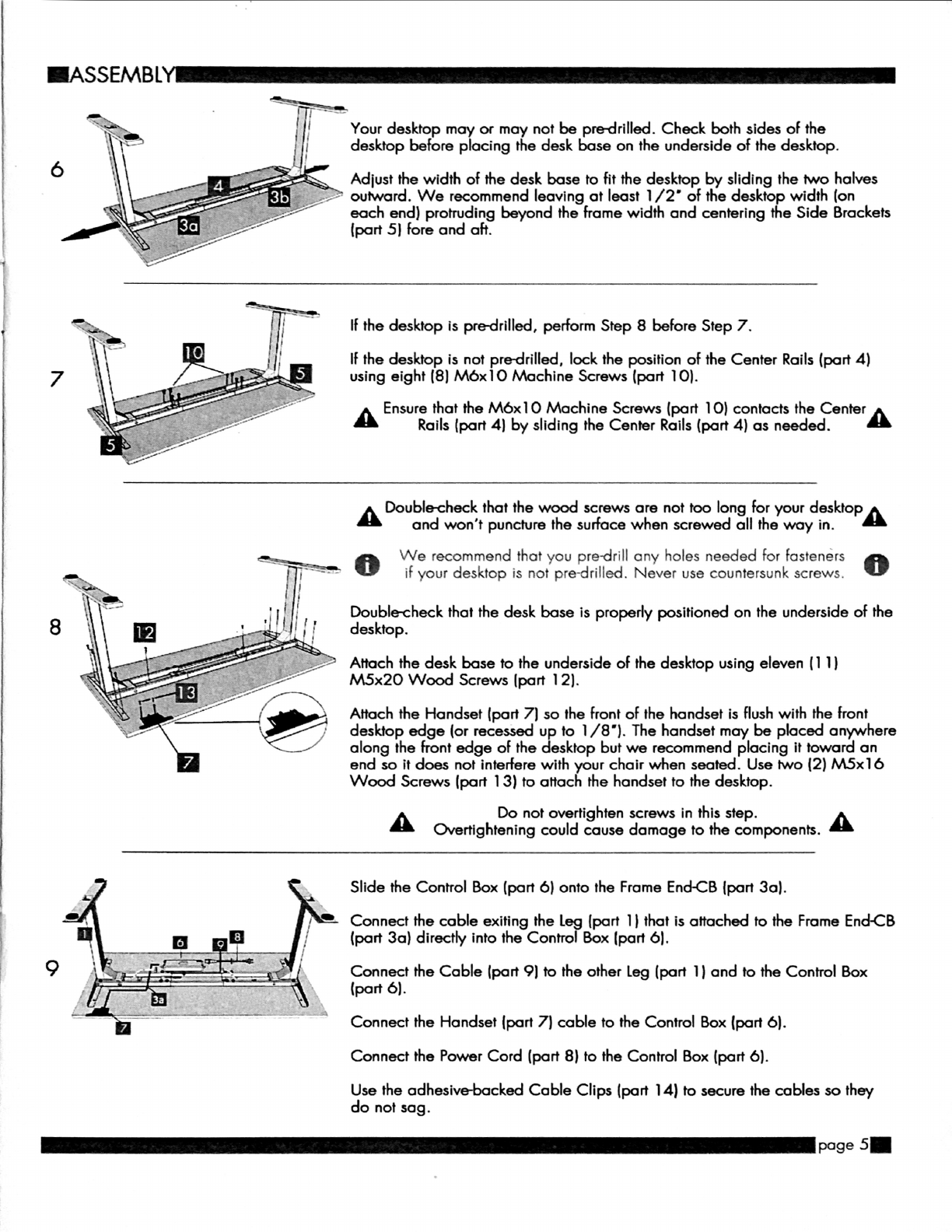
Your
desktop
may
or
may
not
be
predrilled.
Check
both
sides
of
the
desktop
before
placing
the
desk
base
on
the
underside
of
the
desktop.
Adjust
the
width
of
the
desk
base
to
fit
the
desktop
by
sliding
the
two
halves
4“
outward.
We
recommend
leaving
at
least
1/2'
of
the
desktop
width
[on
each
end)
protruding
beyond
the
frame
width
and
centering
the
Side
Brackets
(part
5)
fore
and
aft.
If
the
desktop
is
pre-drilled,
perform
Step
8
before
Step
7.
If
the
desktop
is
not
pre-drilled,
lock
the
position
of
the
Center
Rails (part
4)
using
eight
(8)
be10
Machine
Screws
(port
10).
A
Ensure
that
the
Max]
0
Machine
Screws
(part
10)
contacts
the
Center
A
Rails (part
4]
by
sliding
the
Center
Rails
(part
4)
as
needed.
A
Double-check
that
the
wood
screws
are
not
too
long
for
your
desktop
A
and
won't
puncture
the
surface
when
screwed
all
the
way
in.
0
We
recommend
that
you
predrill
any
holes
needed
for
fasteners
0
if
your
desktop
is
not
pre-drilled.
Never
use
countersunk
screws.
Double-check
that
the
desk
base
is
properly
positioned
on
the
underside
of
the
desktop.
Attach
the
desk
base
to
the
underside
of
the
desktop
using
eleven
(1
l)
M5x20
Wood
Screws
[part
)2).
Attach
the
Handset
(part
7)
so
the
front
of
the
handset
is
flush
with
the
front
desktop
edge
(or
recessed
up
to
l/
8').
The
handset
may
be
placed
anywhere
along
the
front
edge
of
the
desktop
but
we
recommend
placing
it
toward
an
end
so
it
does
not
interfere
with
your
chair
when
seated.
Use
two
(2)
M5xl
6
Wood
Screws
(part
)3)
to
attach
the
handset
to
the
desktop.
A
Do
not
overtighten
screws
in
this
step.
A
Overtightening
could
cause
damage
to
the
components.
Slide
the
Control
Box
(part
6)
onto
the
Frame
End-CB
(part
3a).
Connect
the
cable
exiting
the
Leg
[port
1)
that
is
attached
to
the
Frame
End-CB
(port
3a)
directly
into
the
Control
Box
[part
6).
Connect
the
Cable
(part
9)
to
the
other
Leg
(part
I)
and
to
the
Control
Box
(port
6).
Connect
the
Handset [part
7)
cable
to
the
Control
Box
(part
6).
Connect
the
Power
Cord
(part 8)
to
the
Control
Box
(part
6).
Use
the
adhesive-backed
Cable
Clips
(part
14)
to
secure
the
cables
so
they
do
not
sag.
—mge
5-
.ASSEMBLY—
]
0
Turn
the
assembled
desk
right-side
up.
With
at
least
two
people,
grab
the
DESK
BASE
(not
the
desktop)
and
turn
the
desk
right-side
up.
Adjust
the
pre-installed
glides
on
the
Feet
(part
2)
as
needed.
1 1
Plug
the
Power
Cord
(part
8)
into
a
1
10v
outlet.
IUSE—
A
Make
sure
no
obstacles
are
in
the
desk’s
path.
A
Make
sure
the
desktop
is
not
touching
any
walls.
Make
sure
all
cords
are
appropriate
length
to
accommodate
the
change
in
height.
IMPORTANT:
You
must
RESET
the
desk
prior
to
use.
RESET
PROCEDURE:
Press
and
hold
the
DOWN
button
on
the
Handset
(part
7)
until
the
desk
reaches
its
lowest
height.
H
Release
the
DOWN
button.
Press
and
hold
the
DOWN
button
again
about
10
seconds.
Release
the
DOWN
button.
Press
and
hold
the
DOWN
button
again
until
the
desk
lowers
a
little
bit
more,
slightly
rises
and
stops.
Release
the
DOWN
button.
Your
desk
is
now
ready
to
use.
The
desk
base
can
be
adjusted
by
pressing
and
holding
either
the
UP
or
DOWN
button
until
the
desired
height
is
reached.
If
your
desk
is
not
functioning
properly
it
may
need
to
be
reset.
Follow
the
RESET
procedure
outlined
in
the
USE
section.
If
your
desk
has
a
handset
with
an
LED
readout
and
it
displays
'RST'
(reset),
perform
the
reset
procedure
outlined
in
the
USE
section.
It
the
LED
readout
displays
an
error
message
('Erl
"
-
'Er13')
confirm
that
all
wired
connections
are
secure
(legs
to
cables,
cables
to
control
box).
Then
perlorm
the
reset
procedure
outlined
in
the
USE
section.
It
the
error
message
persists
alter
the
reset
procedure,
contact
your
seller.
If
the
height
between
the
legs
exceeds
1
.5
inches,
stop
the
reset
procedure
&
contact
your
seller.
If
the
handset
displays
'HOT',
let
the
base
cool
down
for 20
minutes.
.SPECIFICATIONS
—
'
Heiht
Rane
26.5"
-
46"
without
deskto
Base
Wit
42'
min.
-
72"
max.
WHL-
1.2"
o:
secon
no
oa
lOOON
10%.
Max.
2
mins
on
18
mins
0
So
start
sto
A
'usta
e
levelin
stus
4
Memory
presets
(some
m
e
s)
IPROGRAMMING
Press
the
DOWN
button
on
the
Handset
(part
7)
until
the
base
reaches
its
lowest
position.
Press
and
hold
the
DOWN
button
again
until
the
LED
display
reads
'RST'.
Press
and
hold
the
1
button
(about
5
seconds)
while
the
LED
flashes
'RST'
and
then
switches
to
either:
Fl
5
l’
l0.l
—-
One-Touch
lO.
2
-—
Constant-Touch
Release
the
1
button.
Press
the
1
button
again
until
the
desired
setting
is
reached.
Once
the
chosen
setting
is
displayed,
release
the
button
and
wait
about
5
seconds
for
the
display
to
return
to
'RST'.
Finish
the
reset
process
by
pressing
and
holding
the
DOWN
button
until
the
desk
lowers
a
little
bit
more,
slightly
rises
and
stops.
Release
the
button.
The
new
program
setting
is
saved
and
your
desk
is
now
ready
to
use.
ISETTING
THE
LED
RETRACTED
HEIGHT
Press
the
DOWN
button
on
the
Handset
(part
7)
until
the
base
reaches
its
lowest
position.
Measure
the
distance
from
floor
to
the
top
surface
at
the
desktop.
It
the
number
on
the
LED
display
does
NOT
match
your
measurement,
follow
these
steps:
Press
and
hold
the
DOWN
button
until
the
LED
display
reads
'RST'.
l:l
El
l—
Press
and
hold
the
'M'
button
(about
5
seconds)
until
the
LED
displays
the
flashing
height.
(It
the
display
returns
to
'RST'
before
the
next
step
is
taken,
repeat
this
step.)
Use
the
UP/
DOWN
buttons
to
change
the
value
of
the
starting
height
so
that
it
matches
your
measurement.
Wait
about
5
seconds
and
the
display
will
return
to
'RST.'
Finish
the
reset
process
by
pressing
and
holding
the
DOWN
button
again
until
the
desk
lowers
a
little
bit
more,
slightly
rises
and
stops.
Release
the
button.
The
new
starting
height
value
is
saved
and
your
desk
is
now
ready
to
use.
Note:
the
LED
display
has
a
$0.]
tolerance.
.SETTING
THE
UPPER
&
LOWER
LIMITS
This
base
is
designed
to
go
to
its
minimum
and
maximum
heights,
allowing
for
the
widest
possible
range.
It
you
prefer
to
change
the
settings
to
a
more
narrow
range,
follow
these
steps:
Make
sure
the
power
is
ON
and
a
number
reads
in
the
LED
display
{it
no
number
appears,
please
follow
the
Reset
procedure
described
in
the
USE
section).
To
Set
the
Upper-Limit
Position:
Use
the
UP/
DOWN
buttons
to
move
the
base
to
the
desired
maximum-height
position.
Press
the
'M'
button
and
release.
Press
the
UP
button
and
release.
The
LED
display
will
flash
'5
-'.
Press
and
hold
the
'M'
button
{about
2
seconds)
until
the
LED
display
changes
to
'999'.
The
display
will
automatically
return
to
the
selected
height.
The
new
upper
limit
is
now
set.
To
Set
the
Lower-Limit
Position:
Use
the
UP/
DOWN
buttons
to
move
the
base
to
the
desired
minimum-height
position.
Press
the
'M'
button
and
release.
Press
the
DOWN
button
and
release.
The
LED
display
will
flash
'5
-'.
Press
and
hold
the
'M'
button
(about
2
seconds)
until
the
LED
display
changes
to
'OOO'.
The
display
will
automatically
return
to
the
selected
height.
The
new
lower
limit
is
now
set.
To
Remove
the
Upper/
Lower
Limit
Positions:
Press
the
'M'
button
and
release.
The
LED
display
will
Hash
'S
-'.
Within
5
seconds,
press
the
'M'
button
again
and
hold
for
2
seconds.The
LED
display
will
change
to
'555'
and
then
automatically
return
to
the
height
display.
The
upper
and
lower
limits
are
now
removed.
A
A
RESET
procedure
requires
the
desk
base
to
full
retract
(beyond
any
lower
limit
set).
Please
ensure
that
you
have
the
proper
clearance
below
the
desk
base.
A
After
the
upper
and
lower
limits
are
set,
the
previous
memory
positions
ll
,
2,
3,
4)
may
be
outside
the
new
range
of
movement.
It
so,
simply
reset
the
memory
positions.
It
you
attempt
to
revise
a
previously
set
upper
or
lower
limit
and
it
is
outside
of
the
existing
range,
you
will
need
to
remove
the
previously
set
upper/
lower
limits
first.
—poge
7-

.HAN
DSET
LOCK
To
lock
the
handset:
Press
and
hold
the
'M'
button
)about
8
seconds)
until
the
[ED
display
switches
to
'S
-'
and
then
to
'LOC.”
Release
the
button.
To
unlock
the
handset:
Press
and
hold
the
'M'
button
(about
8
seconds)
until
the
LED
switches
from
'LOC'
to
the
height
display.
Release
the
button.
.CHANGING
INCHES
TO
CENTIMETERS
Press
the
DOWN
button
on
the
Handset
(part
7)
until
the
base
reaches
its
lowest
position.
Press
and
hold
the
DOWN
button
again
until
the
LED
display
reads
'RST'.
H
E
[—
Press
and
hold
the
2
button
[about
5
seconds)
while
the
LED
flashes
'RST'
and
then
switches
to
either:
10.3
=
cm
10.4
=
inches
Release
the
2
button.
Press
and
hold
the
2
button
again
until
the
desired
setting
is
reached.
Once
the
chosen
setting
is
displayed,
release
the
button
and
wait
about
5
seconds
for
the
display
to
return
to
'RST'.
Finish
the
reset
process
by
pressing
and
holding
the
DOWN
button
until
the
desk
lowers
a
little
bit
more,
slightly
rises
and
stops.
Release
the
button.
The
new
measurement
setting
is
saved
and
your
desk
is
now
ready
to
use.
.CHANGING
ANTI-COLLISION
SENSITIVITY
Press
the
DOWN
button
on
the
Handset
)part
7
)
until
the
base
reaches
its
lowest
position.
Press
and
hold
the
DOWN
button
again
until
the
LED
display
reads
'RST'.
H
E
'—
Press
and
hold
the
UP
button
[about
5
seconds)
while
the
LED
flashes
'RST'
and
then
switches
to
either:
10.5
=
10
kg.
pressure
(most
sensitive)
10.6
=
15
kg
pressure
[middle
setting)
10.7
=
20
kg
pressure
(least
sensitive)
Release
the
UP
button.
Press
and
hold
the
UP
button
again
until
the
desired
setting
is
reached.
Once
the
chosen
setting
is
displayed,
release
the
button
and
wait
about
5
seconds
for
the
display
to
return
to
'RST'.
Finish
the
reset
process
by
pressing
and
holding
the
DOWN
button
until
the
desk
lowers
a
little
bit
more,
slightly
rises
and
stops.
Release
the
button.
The
new
anti-collision
sensitivity
setting
is
saved
and
your
desk
is
now
ready
to
use.
—poge
8-
Table of contents
Other element ergo Indoor Furnishing manuals

Popular Indoor Furnishing manuals by other brands

Stryker
Stryker Position Pro 2920 Operation & maintenance manual

BRW
BRW vsu4s/20/15 Assembly manual

Varier
Varier Wing Assembly instructions

Kvik
Kvik OU849 quick start guide

Seconique Furniture
Seconique Furniture CORONA EXTENDING TABLE Assembly instructions

Schaffenburg
Schaffenburg DEXTRO PLUS Assembly instructions


