Element14 BeagleBone Black INDUSTRIAL User manual

element14 BeagleBone Black
INDUSTRIAL
System Reference Manual
January 2016

element14 is a trademark of Premier Farnell plc 2
© 2016 Premier Farnell plc. All Rights Reserved
For more information on the BeagleBoard compliant program, please visit
http://beagleboard.org/logo
Acknowledgements
The element14 BeagleBone Black Industrial is a “BeagleBoard compliant” product.
It is identical in technical design and functionality as the specified BeagleBoard.org
product (BeagleBone Black) and runs on the version of the software provided by
BeagleBoard.org to element14. General support for this board is available from the
BeagleBoard.org community.
This reference manual as such has been largely adapted from the BeagleBone Black
Systems Reference Manual which is provided care of CircuitCo with acknowledements to
Gerald Coley of BeagleBoard.org. This reference manual includes detailed documentation
for the element14 BeagleBone Black Industrial board, its use and its design. It serves as
the primary resource for reference and technical support.
element14 would like to extend a sincere thank you to Gerald Coley and
Jason Kridner for enabling element14 to be a licensee of the
BeagleBoard compliant program and for their continued support.

element14 is a trademark of Premier Farnell plc 3
© 2016 Premier Farnell plc. All Rights Reserved
BEAGLEBONE DESIGN
These design materials referred to in this document are *NOT SUPPORTED* and DO NOT
constitute a reference design. Only “community” support is allowed via resources at
BeagleBoard.org/discuss.
THERE IS NO WARRANTY FOR THE DESIGN MATERIALS, TO THE EXTENT PERMITTED BY
APPLICABLE LAW. EXCEPT WHEN OTHERWISE STATED IN WRITING THE
COPYRIGHT HOLDERS AND/OR OTHER PARTIES PROVIDE THE DESIGN MATERIALS “AS
IS” WITHOUT WARRANTY OF ANY KIND, EITHER EXPRESSED OR IMPLIED, INCLUDING,
BUT NOT LIMITED TO, THE IMPLIED WARRANTIES OF MERCHANTABILITY AND FITNESS
FOR A PARTICULAR PURPOSE. THE ENTIRE RISK AS TO THE QUALITY AND
PERFORMANCE OF THE DESIGN MATERIALS IS WITH YOU. SHOULD THE DESIGN
MATERIALS PROVE DEFECTIVE, YOU ASSUME THE COST OF ALL NECESSARY
SERVICING, REPAIR OR CORRECTION.
This board was designed as an evaluation and development tool. It was not designed with any
other application in mind. As such, these design materials may or may not be suitable for any
other purposes. If used, the design material becomes your responsibility as to whether or not it
meets your specific needs or your specific applications and may require changes to meet your
requirements.

element14 is a trademark of Premier Farnell plc 4
© 2016 Premier Farnell plc. All Rights Reserved
BEAGLEBONE BLACK ADDITIONAL TERMS
element14 and BeagleBoard.org (Supplier) provide the enclosed BeagleBone under the following conditions:
The user assumes all responsibility and liability for proper and safe handling of the goods. Further, the user
indemnifies Supplier from all claims arising from the handling or use of the goods.
Should the element14 BeagleBone Black Industrial not meet the specifications indicated in the System Reference
Manual, the element14 BeagleBone Black Industrial may be returned to the distributor of purchase for a full refund
according to the terms and conditions offered by them.
Please read the System Reference Manual and, specifically, the Warnings and Restrictions notice in the Systems
Reference Manual prior to handling the product. This notice contains important safety information about temperatures and
voltages.
No license is granted under any patent right or other intellectual property right of Supplier covering or relating to any
machine, process, or combination in which such Supplier products or services might be or are used. The Supplier
currently deals with a variety of customers for products, and therefore our arrangement with the user is not exclusive. The
Supplier assumes no liability for applications assistance, customer product design, software performance, or infringement
of patents or services described herein.
UNITED STATES FCC AND CANADA IC REGULATORY COMPLIANCE INFORMATION
The element14 BeagleBone Black Industrial is annotated to comply with Part 15 of the FCC Rules. Operation is
subject to the following two conditions: (1) This device may not cause harmful interference, and (2) this device must
accept any interference received, including interference that may cause undesired operation. Changes or modifications
not expressly approved by the party responsible for compliance could void the user’s authority to operate the equipment.
This Class A or B digital apparatus complies with Canadian ICES-003. Changes or modifications not expressly approved
by the party responsible for compliance could void the user’s authority to operate the equipment.
Cet appareil numérique de la classe A ou B est conforme à la norme NMB-003 du Canada. Les changements ou les
modifications pas expressément approuvés par la partie responsible de la conformité ont pu vider l’autorité de l'utilisateur
pour actionner l'équipement.

BEAGLEBONE WARNINGS, RESTRICTIONS AND DISCLAIMERS
For Feasibility Evaluation Only, in Laboratory/Development Environments. The element14 BeagleBone Black
Industrial Industrial is not a complete product. It is intended solely for use for preliminary feasibility evaluation in
laboratory/development environments by technically qualified electronics experts who are familiar with the dangers and
application risks associated with handling electrical mechanical components, systems and subsystems. It should not be
used as all or part of a finished end product.
Your Sole Responsibility and Risk you acknowledge, represent, and agree that:
1. You have unique knowledge concerning Federal, State and local regulatory requirements (including but not
limited to Food and Drug Administration regulations, if applicable) which relate to your products and which relate to your
use (and/or that of your employees, affiliates, contractors or designees) of the BeagleBone for evaluation, testing and
other purposes.
2. You have full and exclusive responsibility to assure the safety and compliance of your products with all such laws and
other applicable regulatory requirements, and also to assure the safety of any activities to be conducted by you and/or
your employees, affiliates, contractors or designees, using the BeagleBone. Further, you are responsible to
assure that any interfaces (electronic and/or mechanical) between the BeagleBone and any human body are designed
with suitable isolation and means to safely limit accessible leakage currents to minimize the risk of electrical shock
hazard.
3. Since the BeagleBone is not a completed product, it may not meet all applicable regulatory and safety compliance
standards which may normally be associated with similar items. You assume full responsibility to determine and/or
assure compliance with any such standards and related certifications as may be applicable. You will employ reasonable
safeguards to ensure that your use of the BeagleBone will not result in any property damage, injury or death, even if
the BeagleBone should fail to perform as described or expected.
Certain Instructions. It is important to operate the e l e m e n t 1 4 BeagleBone Black Industrial within Supplier’s
recommended specifications and environmental considerations per the user guidelines. Exceeding the specified
BeagleBone ratings (including but not limited to input and output voltage, current, power, and environmental ranges)
may cause property damage, personal injury or death. If there are questions concerning these ratings please contact
the Supplier representative prior to connecting interface electronics including input power and intended loads. Any
loads applied outside of the specified output range may result in unintended and/or inaccurate operation and/or
possible permanent damage to the BeagleBone and/or interface electronics. Please consult the System Reference
Manual prior to connecting any load to the BeagleBone output. If there is uncertainty as to the load specification,
please contact the Supplier representative. During normal operation, some circuit components may have case
temperatures greater than 60 C as long as the input and output are maintained at a normal ambient operating
temperature. These components include but are not limited to linear regulators, switching transistors, pass transistors,
and current sense resistors which can be identified using the BeagleBone schematic located at the link in the
BeagleBone System Reference Manual. When placing measurement probes near these devices during normal
operation, please be aware that these devices may be very warm to the touch. As with all electronic evaluation tools,
only qualified personnel knowledgeable in electronic measurement and diagnostics normally found in development
environments should use the BeagleBone.
Agreement to Defend, Indemnify and Hold Harmless. You agree to defend, indemnify and hold the Suppliers, its
licensors and their representatives harmless from and against any and all claims, damages, losses, expenses,
costs and liabilities (collectively, "Claims") arising out of or in connection with any use of the BeagleBone that is
not in accordance with the terms of the agreement. This obligation shall apply whether Claims arise under law of tort or
contract or any other legal theory, and even if the BeagleBone fails to perform as described or expected.
Safety-Critical or Life-Critical Applications. If you intend to evaluate the components for possible use in safety
critical applications (such as life support) where a failure of the Sup p li e r’s product would reasonably be expected
to cause severe personal injury or death, such as devices which are classified as FDA Class III or similar
classification, then you must specifically notify Suppliers of such intent and enter into a separate Assurance and
Indemnity Agreement.

element14 is a trademark of Premier Farnell plc 6
© 2016 Premier Farnell plc. All Rights Reserved
Before returning the board, please visit
BeagleBoard.org/support
For up to date SW images and technical information refer to
http://elinux.org/Beagleboard:BeagleBoneBlack
All support for this board is provided via community support at
www.beagleboard.org/discuss

element14 is a trademark of Premier Farnell plc
© 2016 Premier Farnell plc. All Rights Reserved
Table of
Contents
Contents
1.0
INTRODUCTION .......................................................................................................................................................12
2.0
CHANGE HISTORY...................................................................................................................................................12
2.1
Board Changes............................................................................................................................................... 12
3.0
CONNECTING UP YOUR ELEMENT14 BEAGLEBONE BLACK INDUSTRIAL ...................................................................12
3.1
What’s In the Box ........................................................................................................................................... 13
3.2
Main Connection Scenarios........................................................................................................................... 13
3.3
Tethered To A PC............................................................................................................................................ 14
3.4
Standalone w/Display and Keyboard/Mouse ................................................................................................. 17
4.0
ELEMENT14 BEAGLEBONE BLACK INDUSTRIAL OVERVIEW....................................................................................23
4.1
BeagleBone Compatibility ............................................................................................................................. 24
4.2
element14 BeagleBone Black Industrial Features and Specification............................................................. 25
4.3
Board Component Locations.......................................................................................................................... 26
5.0
ELEMENT14 BEAGLEBONE BLACK INDUSTRIAL HIGH LEVEL SPECIFICATION .........................................................28
5.1
Block Diagram............................................................................................................................................... 28
5.2
Processor ....................................................................................................................................................... 28
5.3
Memory .......................................................................................................................................................... 29
5.4
Power Management ....................................................................................................................................... 30
5.5
PC USB Interface........................................................................................................................................... 31
5.6
Serial Debug Port ........................................................................................................................................... 31
5.7
USB1 Host Port .............................................................................................................................................. 31
5.8
Power Sources ................................................................................................................................................ 31
5.9
Reset Button ................................................................................................................................................... 32
5.10
Power Button ................................................................................................................................................. 32
5.11
Indicators....................................................................................................................................................... 32
5.12
CTI JTAG Header .......................................................................................................................................... 33
5.13
HDMI Interface.............................................................................................................................................. 33
5.14
Cape Board Support....................................................................................................................................... 33
6.0
DETAILED HARDWARE DESIGN ...............................................................................................................................34
6.1
Power Section ................................................................................................................................................ 35
6.1.1
TPS65217C PMIC ......................................................................................................................................... 35
6.1.2
DC Input ........................................................................................................................................................ 37
6.1.3
USB Power..................................................................................................................................................... 38
6.1.4
Power Selection ............................................................................................................................................. 39
6.1.5
Power Button ................................................................................................................................................. 40
6.1.6
Battery Access Pads....................................................................................................................................... 40
6.1.7
Power Consumption....................................................................................................................................... 41
6.1.8
Processor Interfaces....................................................................................................................................... 41

element14 is a trademark of Premier Farnell plc 8
© 2016 Premier Farnell plc. All Rights Reserved
6.1.9
Power Rails.................................................................................................................................................... 42
6.1.10
Power LED ................................................................................................................................................ 46
6.1.11
TPS65217C Power Up Process ................................................................................................................ 46
6.1.12
Processor Control Interface....................................................................................................................... 47
6.1.13
Low Power Mode Support ........................................................................................................................ 47
6.2
SITARA AM3358BZCZA100 PROCESSOR...............................................................................................................48
6.2.1
Description..................................................................................................................................................... 48
6.2.2
High Level Features ....................................................................................................................................... 49
6.2.3
Documentation............................................................................................................................................... 49
6.2.4
Crystal Circuitry ............................................................................................................................................ 50
6.2.5
Reset Circuitry ............................................................................................................................................... 50
6.2.6
Memory Device .............................................................................................................................................. 51
6.2.7
DDR3L Memory Design................................................................................................................................. 52
6.2.8
Power Rails.................................................................................................................................................... 54
6.2.9
VREF.............................................................................................................................................................. 54
6.3
4GB EMMC MEMORY ............................................................................................................................................55
6.3.1
eMMC Device ................................................................................................................................................ 55
6.3.2
eMMC Circuit Design .................................................................................................................................... 55
6.4
BOARD ID EEPROM ..............................................................................................................................................57
6.5
MICRO SECURE DIGITAL .........................................................................................................................................58
6.5.1
microSD Design ............................................................................................................................................. 58
6.6
USER LEDS.............................................................................................................................................................59
6.7
BOOT CONFIGURATION ...........................................................................................................................................60
6.7.1
Boot Configuration Design ............................................................................................................................ 60
6.8
DEFAULT BOOT OPTIONS ........................................................................................................................................61
6.9
10/100 ETHERNET ...................................................................................................................................................61
6.9.1
Ethernet Processor Interface ......................................................................................................................... 62
6.9.2
Ethernet Connector Interface......................................................................................................................... 63
6.9.3
Ethernet PHY Power, Reset, and Clocks ........................................................................................................ 64
6.9.4
LAN8710A Mode Pins.................................................................................................................................... 65
6.10
HDMI INTERFACE...................................................................................................................................................66
6.10.1
Supported Resolutions ............................................................................................................................... 66
6.10.2
HDMI Framer............................................................................................................................................ 67
6.10.3
HDMI Video Processor Interface............................................................................................................... 67
6.10.4
HDMI Control Processor Interface ........................................................................................................... 68
6.10.5
Interrupt Signal.......................................................................................................................................... 68
6.10.6
Audio Interface .......................................................................................................................................... 69
6.10.7
Power Connections.................................................................................................................................... 70
6.10.8
HDMI Connector Interface........................................................................................................................ 70
6.11
USB HOST ..............................................................................................................................................................72

element14 is a trademark of Premier Farnell plc 9
© 2016 Premier Farnell plc. All Rights Reserved
6.11.1
Power Switch ............................................................................................................................................. 72
6.11.2
ESD Protection.......................................................................................................................................... 72
6.11.3
Filter Options ............................................................................................................................................ 72
6.12
PRU-ICSS ..............................................................................................................................................................73
6.12.1
PRU-ICSS Features ................................................................................................................................... 73
6.12.2
PRU-ICSS Block Diagram ........................................................................................................................ 73
6.12.3
PRU-ICSS Pin Access ............................................................................................................................... 74
7.0
CONNECTORS ..........................................................................................................................................................75
7.1
Expansion Connectors ................................................................................................................................... 75
7.2
Power Jack..................................................................................................................................................... 80
7.3
USB Client ..................................................................................................................................................... 81
7.4
USB Host ....................................................................................................................................................... 82
7.5
Serial Header................................................................................................................................................. 83
7.6
HDMI............................................................................................................................................................. 86
7.7
microSD ......................................................................................................................................................... 87
7.8
Ethernet.......................................................................................................................................................... 88
7.9
JTAG Connector............................................................................................................................................. 88
8.0
CAPE BOARD SUPPORT............................................................................................................................................89
8.1
element14 BeagleBone Black Industrial Cape Compatibility ........................................................................ 90
8.2
EEPROM ....................................................................................................................................................... 92
8.3
Pin Usage Consideration ............................................................................................................................... 99
8.4
Expansion Connectors ................................................................................................................................. 100
8.5
Signal Usage................................................................................................................................................ 104
8.6
Cape Power.................................................................................................................................................. 106
8.7
Mechanical................................................................................................................................................... 107
9.0
ELEMENT14 BEAGLEBONE BLACK INDUSTRIAL MECHANICAL ............................................................................. 110
9.1
Dimensions and Weight................................................................................................................................ 110
9.2
Silkscreen and Component
Locations ........................................................................................................ 110
10.0
P
ICTURES
............................................................................................................................................................ 113
11.0
SUPPORT INFORMATION......................................................................................................................................... 114
11.1
Hardware Design ......................................................................................................................................... 114
11.2
Software Updates ......................................................................................................................................... 115
11.3
RMA Support................................................................................................................................................ 116
11.4
Trouble Shooting HDMI Issues.................................................................................................................... 117

element14 is a trademark of Premier Farnell plc 10
© 2016 Premier Farnell plc. All Rights Reserved
FIGURES
FIGURE 1 KIT CONTENTS .................................................................................................... 13
FIGURE 2 TETHERED CONFIGURATION ............................................................................ 14
FIGURE 3 USB CONNECTION TO THE BOARD .................................................................. 15
FIGURE 4 BOARD POWER LED ........................................................................................... 15
FIGURE 5 BOARD BOOT STATUS........................................................................................ 16
FIGURE 6 DESKTOP CONFIGURATION .............................................................................. 17
FIGURE 7 CONNECT MICROHDMI CABLE TO THE MONITOR.......................................... 18
FIGURE 8 DVI-D TO HDMI ADAPTER................................................................................... 18
FIGURE 9 WIRELESS KEYBOARD AND MOUSE COMBO ................................................ 18
FIGURE 10 CONNECT KEYBOARD AND MOUSE RECEIVER TO THE BOARD ................. 19
FIGURE 11 KEYBOARD AND MOUSE HUBS......................................................................... 19
FIGURE 12 ETHERNET CABLE CONNECTION ..................................................................... 20
FIGURE 13 EXTERNAL DC POWER....................................................................................... 20
FIGURE 14 CONNECT MICROHDMI CABLE TO THE BOARD.............................................. 21
FIGURE 15 BOARD BOOT STATUS........................................................................................ 21
FIGURE 16 DESKTOP SCREEN.............................................................................................. 22
FIGURE 17 CONNECTORS, LEDS AND SWITCHES ............................................................. 26
FIGURE 18 KEY COMPONENTS............................................................................................. 27
FIGURE 19 ELEMENT14 BEAGLEBONE BLACK INDUSTRIAL KEY COMPONENTS ......... 28
FIGURE 20 ELEMENT14 BEAGLEBONE BLACK INDUSTRIAL BLOCK DIAGRAM.............. 34
FIGURE 21 HIGH LEVEL POWER BLOCK DIAGRAM ............................................................ 35
FIGURE 22 TPS65217C BLOCK DIAGRAM ............................................................................ 37
FIGURE 23 TPS65217 DC CONNECTION .............................................................................. 38
FIGURE 24 USB POWER CONNECTIONS ............................................................................. 39
FIGURE 25 POWER RAILS...................................................................................................... 43
FIGURE 26 POWER RAIL POWER UP SEQUENCING .......................................................... 45
FIGURE 27 TPS65217C POWER SEQUENCING TIMING...................................................... 45
FIGURE 28 POWER PROCESSOR INTERFACES ................................................................. 46
FIGURE 29 SITARA AM3358BZCZ BLOCK DIAGRAM........................................................... 48
FIGURE 30 PROCESSOR CRYSTALS.................................................................................... 50
FIGURE 31 BOARD RESET CIRCUITRY ................................................................................ 51
FIGURE 32 DDR3L MEMORY DESIGN ................................................................................... 53
FIGURE 33 DDR3L VREF DESIGN.......................................................................................... 54
FIGURE 34 EMMC MEMORY DESIGN.................................................................................... 56
FIGURE 35 EEPROM DESIGN REV A5................................................................................... 57
FIGURE 36 MICROSD DESIGN ............................................................................................... 58
FIGURE 37 USER LEDS .......................................................................................................... 59
FIGURE 38 PROCESSOR BOOT CONFIGURATION DESIGN .............................................. 60
FIGURE 39 PROCESSOR BOOT CONFIGURATION ............................................................. 61
FIGURE 40 ETHERNET PROCESSOR INTERFACE.............................................................. 62
FIGURE 41 ETHERNET CONNECTOR INTERFACE.............................................................. 63
FIGURE 42 ETHERNET. PHY, POWER, RESET AND CLOCKS............................................ 64
FIGURE 43 ETHERNET PHY MODE PINS.............................................................................. 65
FIGURE 44 HDMI FRAMER PROCESSOR INTERFACE........................................................ 68
FIGURE 45 24.576MHZ OSCILLATOR .................................................................................... 69
FIGURE 46 HDMI POWER CONNECTIONS ........................................................................... 70
FIGURE 47 CONNECTOR INTERFACE CIRCUITRY ............................................................. 71
FIGURE 48 USB HOST CIRCUITRY........................................................................................ 72
FIGURE 49 PRU-ICSS BLOCK DIAGRAM............................................................................... 73
FIGURE 50 EXPANSION CONNECTOR LOCATION .............................................................. 75
FIGURE 51 5VDC POWER JACK ............................................................................................ 80

element14 is a trademark of Premier Farnell plc 11
© 2016 Premier Farnell plc. All Rights Reserved
FIGURE 52 USB CLIENT CONNECTOR ................................................................................. 81
FIGURE 53 USB HOST CONNECTOR .................................................................................... 82
FIGURE 54 SERIAL DEBUG HEADER .................................................................................... 83
FIGURE 55 FTDI USB TO SERIAL ADAPTER......................................................................... 84
FIGURE 56 SERIAL CONNECTOR.......................................................................................... 84
FIGURE 57 HDMI CONNECTOR ............................................................................................. 86
FIGURE 58 HDMI CABLE......................................................................................................... 86
FIGURE 59 MICROSD CONNECTOR...................................................................................... 87
FIGURE 60 ETHERNET CONNECTOR ................................................................................... 88
FIGURE 61 EXPANSION BOARD EEPROM WITHOUT WRITE PROTECT .......................... 93
FIGURE 62 EXPANSION BOARD EEPROM WRITE PROTECT ............................................ 94
FIGURE 63 EXPANSION BOOT PINS ..................................................................................... 99
FIGURE 64 SINGLE EXPANSION CONNECTOR ................................................................. 100
FIGURE 65 SINGLE CAPE EXPANSION CONNECTOR ...................................................... 101
FIGURE 66 EXPANSION CONNECTOR................................................................................ 102
FIGURE 67 STACKED CAPE EXPANSION CONNECTOR................................................... 102
FIGURE 68 STACKED W/SIGNAL STEALING EXPANSION CONNECTOR ........................ 103
FIGURE 69 CONNECTOR PIN INSERTION DEPTH............................................................. 104
FIGURE 70 CAPE BOARD DIMENSIONS ............................................................................. 108
FIGURE 71 BOARD DIMENSIONS ........................................................................................ 110
FIGURE 72 COMPONENT SIDE SILKSCREEN .................................................................... 111
FIGURE 73 CIRCUIT SIDE SILKSCREEN............................................................................. 112
FIGURE 74 TOP SIDE ............................................................................................................ 113
FIGURE 75 BOTTOM SIDE .................................................................................................... 114
FIGURE 76 SERIAL NUMBER LOCATION ............................................................................ 116
FIGURE 78 SERIAL NUMBER FORMAT ............................................................................... 116
TABLES
TABLE 1
ELEMENT14 BEAGLEBONE BLACK INDUSTRIAL FEATURES ........................ 25
TABLE 2
ELEMENT14 BEAGLEBONE BLACK INDUSTRIAL BATTERY PINS.................. 40
TABLE 3
ELEMENT14 BEAGLEBONE BLACK INDUSTRIAL POWER CONSUMPTION (MA@5V)
41
TABLE 4
PROCESSOR FEATURES.................................................................................... 49
TABLE 5
EMMC BOOT PINS ............................................................................................... 56
TABLE 6
EEPROM CONTENTS .......................................................................................... 57
TABLE 7
USER LED CONTROL SIGNALS/PINS ................................................................ 59
TABLE 8
HDMI SUPPORTED MONITOR RESOLUTIONS ................................................. 66
TABLE 9
TDA19988 I2C ADDRESS..................................................................................... 68
TABLE 10
PRU0 AND PRU1 ACCESS .................................................................................. 74
TABLE 11
EXPANSION HEADER P8 PINOUT...................................................................... 77
TABLE 12
EXPANSION HEADER P9 PINOUT...................................................................... 79
TABLE 13
J1 SERIAL HEADER PINS.................................................................................... 84
TABLE 14
P8 LCD CONFLICT PINS...................................................................................... 90
TABLE 15
P8 EMMC CONFLICT PINS .................................................................................. 91
TABLE 16 EXPANSION BOARD EEPROM ......................................................................... 94
TABLE 17
EEPROM PIN USAGE........................................................................................... 97
TABLE 18
SINGLE CAPE CONNECTORS .......................................................................... 101
TABLE 19
STACKED CAPE CONNECTORS ...................................................................... 102
TABLE 20
EXPANSION VOLTAGES ................................................................................... 106

element14 is a trademark of Premier Farnell plc 12
© 2016 Premier Farnell plc. All Rights Reserved
1.0 Introduction
The element14 BeagleBone Black Industrial is based on the BeagleBone Black Rev C
design and supports a wider operating temperature range and is conformally coated,
making it well suited for industrial applications and environments. It is identical in
technical design and functionality as the specified BeagleBoard.org product
(BeagleBone Black rev C) and runs on the version of the software provided by
BeagleBoard.org to element14. General support for this board is available from the
BeagleBoard.org community.
This document is the System Reference Manual for the element14 BeagleBone
Black Industrial and covers its use and design. The board will primarily be referred to in
the remainder of this document simply as the board, although it may also be referred to
as the e l e m e n t 1 4 B e a g l e B o n e B l a c k I n d u s t r i a l as a reminder. There are
also references to the original BeagleBone as well, and will be referenced as simply
BeagleBone.
This design is subject to change without notice as we will work to keep improving the
design as the product matures based on feedback and experience. Software updates
will be frequent and will be independent of the hardware revisions and as such not result
in a change in the revision number.
Make sure you check the support Wiki frequently for the most up to date information.
http://elinux.org/Beagleboard:BeagleBoneBlack
2.0 Change History
This section describes the change history of this document and board. Document changes
are not always a result of a board change.
2.1 Board Changes
2.1.1 Rev A (Part#: BBONE-BLACK-IND-4G)
•The BeagleBone Black Industrial board is based on the BeagleBone Black Rev C
design and board configuration.
For details on change history, board changes and revisions, please refer to the wiki
at http://elinux.org/Beagleboard:BeagleBoneBlack
3.0 Connecting up Your element14 BeagleBone Black Industrial
element14 is a trademark of Premier Farnell plc 13
© 2016 Premier Farnell plc. All Rights Reserved
This section provides instructions on how to hook up your board. Two scenarios will be
discussed:
1) Tethered to a PC and
2) As a standalone development platform in a desktop PC configuration.
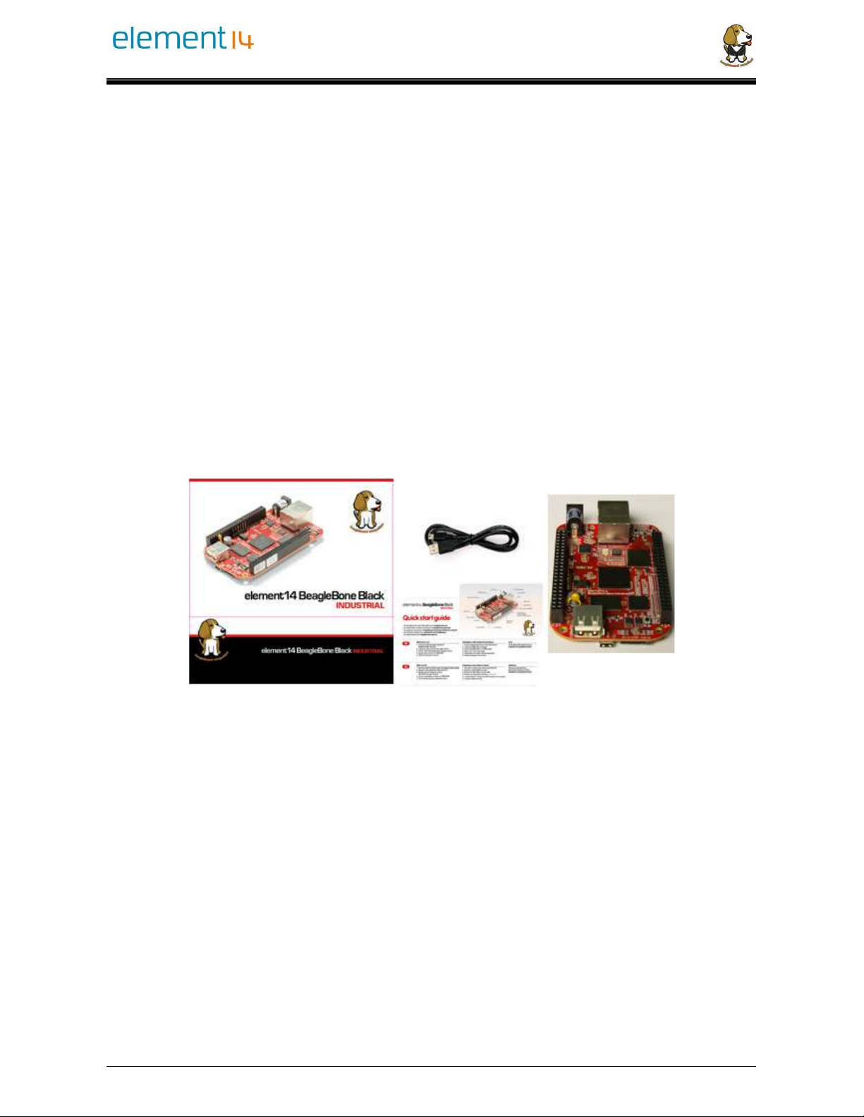
3.1 What’s In the Box
In the box you will find three main items as shown in Figure 1.
•element14 BeagleBone Black Industrial
•miniUSB to USB Type A Cable
•Quick Start Guide.
This is sufficient for the tethered scenario and creates an out of box experience where the
board can be used immediately with no other equipment needed.
Figure 1 Kit Contents
3.2 Main Connection Scenarios
This section will describe how to connect the board for use. This section is basically a
slightly more detailed description of the Quick Start Guide that came in the box. There is
also a Quick Start Guide document on the board that should also be refereed. The intent
here is that someone looking to purchase the board will be able to read this section and
get a good idea as to what the initial set up will be like.
The board can be configured in several different ways, but we will discuss the two most
common scenarios as described in the Quick Start Guide card that comes in the box.

element14 is a trademark of Premier Farnell plc 14
© 2016 Premier Farnell plc. All Rights Reserved
•Tethered to a PC via the USB cable
oBoard is accessed as a storage drive
oOr a RNDIS Ethernet connection.
•Standalone desktop
oDisplay
oKeyboard and mouse
oExternal 5V power supply
Each of these configurations is discussed in general terms in the following sections.
For an up-to-date list of confirmed working accessories please go to
http://elinux.org/Beagleboard:BeagleBone_Black_Accessories
3.3 Tethered To A PC
In this configuration, the board is powered by the PC via the provided USB cable--no
other cables are required. The board is accessed either as a USB storage drive or via the
browser on the PC. You need to use either Firefox or Chrome on the PC, IEx will not
work properly. Figure 2 shows this configuration.
Figure 2 Tethered Configuration
All the power for the board is provided by the PC via the USB cable. In some instances,
the PC may not be able to supply sufficient power for the board. In that case, an external
5VDC power supply can be used, but this should rarely be necessary.
3.3.1 Connect the Cable to the Board
1. Connect the small connector on the USB cable to the board as shown in Figure 3.
The connector is on the bottom side of the board.
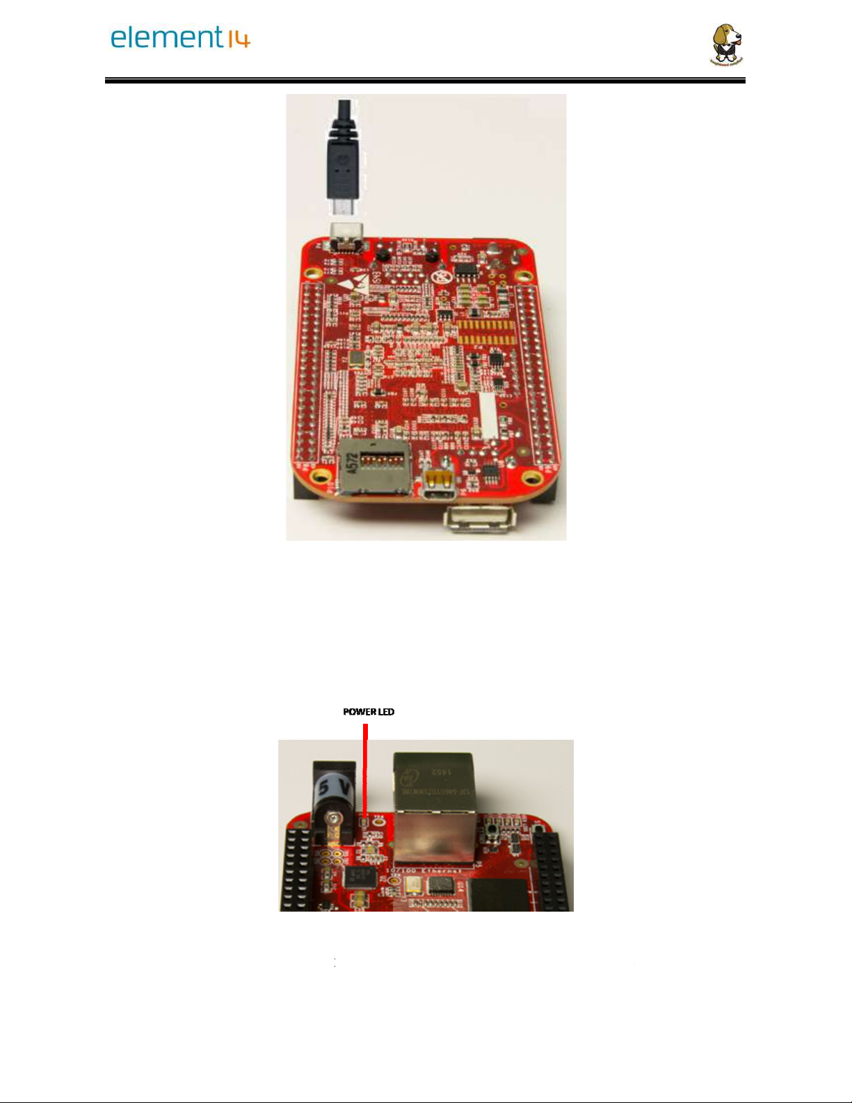
Figure
3
2. Connect the large conn
ec
3. The board will power on
a
Figure
4. When the board starts
to
power, the LEDs will co
me on in
3
USB Connection to the Board
ec
tor of the USB cable to your PC or
laptop USB
a
nd the power LED will be on as shown in
F
Figure
4 Board Power LED
to
the booting process started by the pro
c
me on in
sequence as shown in Figure 5 b
e
laptop USB
port.
F
igure 4 below.
c
ess of applying
e
low. It will take

element14 is a trademark of Premier Farnell plc 16
© 2016 Premier Farnell plc. All Rights Reserved
a few seconds for the status LEDs to come on, so be patient. The LEDs will be
flashing in an erratic manner as it begins to boot the Linux kernel.
Figure 5 Board Boot Status
3.3.2 Accessing the Board as a Storage Drive
The board will appear around a USB Storage drive on your PC after the kernel has
booted, which will take a round 10 seconds. The kernel on the board needs to boot before
the port gets enumerated. Once the board appears as a storage drive, do the following:
1) Open the USB Drive folder.
2) Click on the file named start.html
3) The file will be opened by your browser on the PC and you should get a display
showing the Quick Start Guide.
4) Your board is now operational! Follow the instructions on your PC screen.
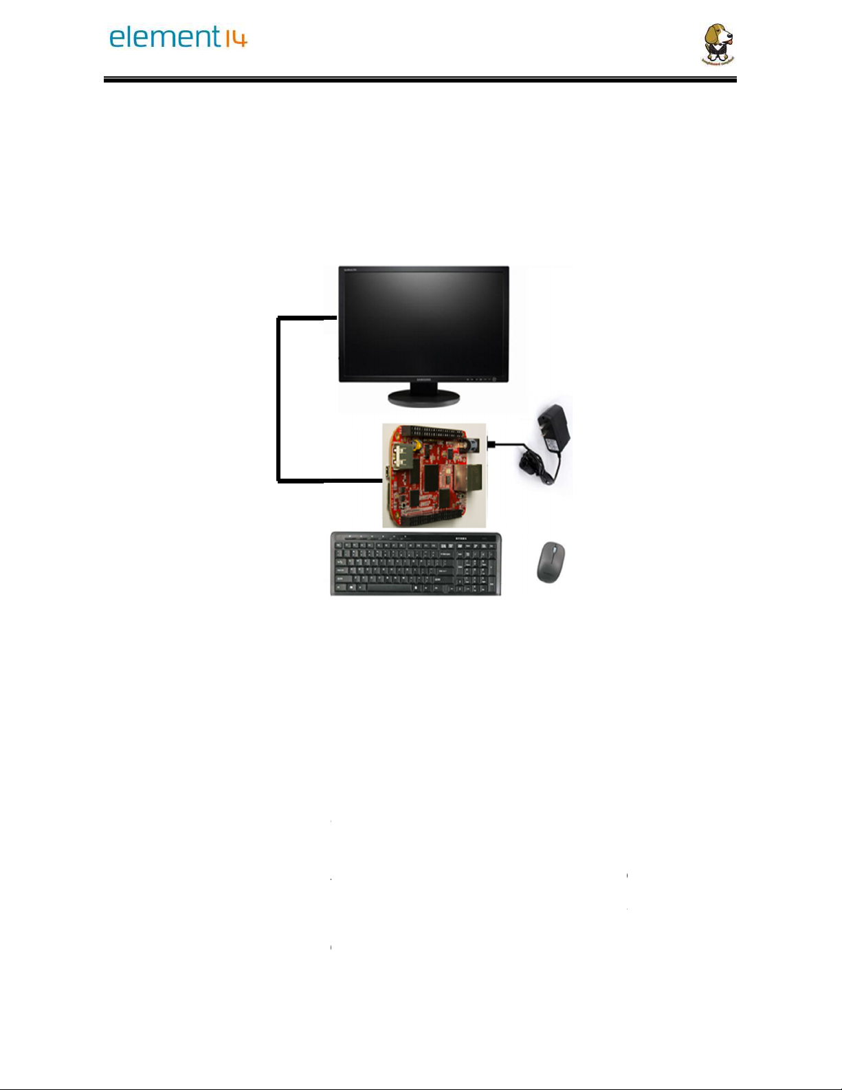
3.4 Standalone w/Disp
lay
In this configuration, the board
wo
PC as shown in
Figure 6
. It
whatever you need it to do. I
t
These accessories and instructi
ons
Figure
Optionally an Ethernet cable ca
n
3.4.1 Required Accessories
In order to use the board in t
his con
•
(1) 5 VDC 1A powe
r su
•
(1) HDMI monitor or
a
capability).
•
(1) Micro HDMI to H
DM
•
(1) USB wireless key
b
•
(1) USB HUB (OPTI
O
need to use a USB
Hub if
lay
and Keyboard/Mouse
wo
rks more like a PC, totally free from any
allows you to create your code to mak
e
t
will however require certain common
P
ons
are described in the following section.
Figure
6 Desktop Configuration
n
also be used for network access.
his con
figuration, you will need the following
ac
r su
pply
a
DVI-D monitor. (
NOTE:
Only HDMI will g
ive
DM
I cable or a Micro HDMI to DVI-D adapte
r.
b
oard and mouse combo.
O
NAL). The board has only one USB host
port, so
Hub if
your keyboard and mouse require
s two ports.
connection to a
e
the board do
P
C accessories.
ac
cessories:
ive
you audio
r.
port, so
you may
s two ports.
For an up-to-date list of confirmed working accessories please go to
http://elinux.org/Beagleboard:BeagleBone_Black_Accessories
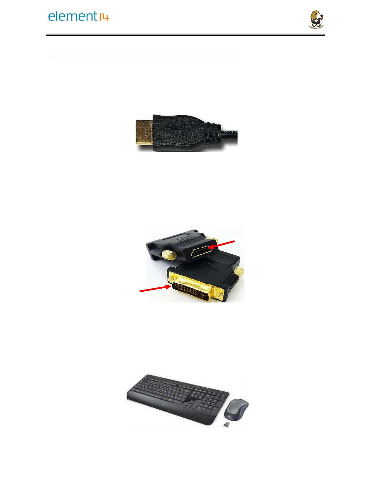
3.4.2 Connecting Up the Board
1. Connect the big end of the HDMI cable as shown in
Figure 7
to your HDMI monitor.
Refer to your monitor Owner’s Manual for the location of your HDMI port. If you
have a DVI-D Monitor go to
Step 3
, otherwise proceed to
Step 4.
Figure 7 Connect microHDMI Cable to the Monitor
2. If you have a DVI-D monitor you must use a DVI-D to HDMI adapter in addition to
your HDMI cable. An example is shown in
Figure 8
below from two perspectives.
If you use this configuration, you will not have audio support.
To microHDMI Cable
To the Monitor
3. If you have a single wireless keyboard and mouse combination such as seen in
Figure
9
below, you need to plug the receiver in the USB host port of the board as
shown in
Figure 10
.
Figure 8 DVI-D to HDMI Adapter
Figure 9 Wireless Keyboard and Mouse Combo
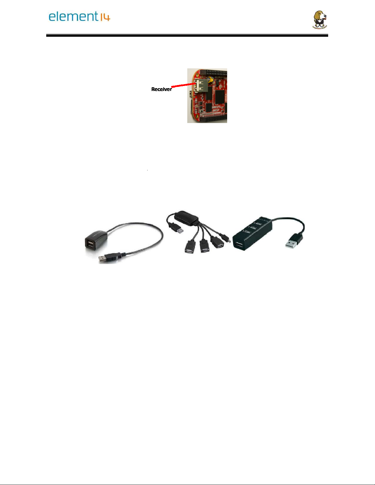
Figure 10
If you have a wired USB keyboard requiring two USB ports, you will need a HUB similar to
the ones shown in
Figure 11
. You may want to have more than one port for other devices.
Note that the board can only supply up to 500mA, so if you plan to load it down, it will need
to be externally powered.
4. Connect the Ethernet Cable
If you decide you wan
t to connect to your local area network, an Ethernet cable can be
used. Connect the Ethernet Cable to the Ethernet port as shown in
standard 100M Ethernet cable should work.
Figure
Connect Keyboard and Mouse Receiver to the Board
If you have a wired USB keyboard requiring two USB ports, you will need a HUB similar to
. You may want to have more than one port for other devices.
Note that the board can only supply up to 500mA, so if you plan to load it down, it will need
4. Connect the Ethernet Cable
t to connect to your local area network, an Ethernet cable can be
used. Connect the Ethernet Cable to the Ethernet port as shown in
Figure 12
standard 100M Ethernet cable should work.
Figure
11 Keyboard and Mouse Hubs
Connect Keyboard and Mouse Receiver to the Board
If you have a wired USB keyboard requiring two USB ports, you will need a HUB similar to
. You may want to have more than one port for other devices.
Note that the board can only supply up to 500mA, so if you plan to load it down, it will need
t to connect to your local area network, an Ethernet cable can be
Figure 12
. Any

Figure
Apply Power
The final step is to plug in the DC power supply to the DC power jack as shown in
13
below.
Figure
5. The cable needed to c
onn
microHDMI connector e
nd
side of the board a
s shown in
Figure
12 Ethernet Cable Connection
The final step is to plug in the DC power supply to the DC power jack as shown in
Figure
13 External DC Power
onn
ect to your display is a microHDMI to HD
M
nd
to the board at this time. The connector
is
s shown in
Figure 14
below.
The final step is to plug in the DC power supply to the DC power jack as shown in
Figure
M
I. Connect the
is
on the bottom
This manual suits for next models
1
Table of contents
Other Element14 Motherboard manuals


