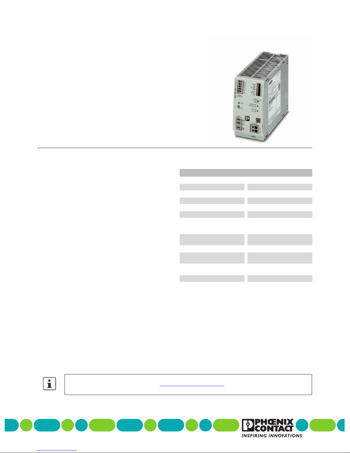
TRIO-UPS-2G/1AC/24DC/10
107432_en_02 PHOENIX CONTACT 10 / 30
5 Safety and installation notes
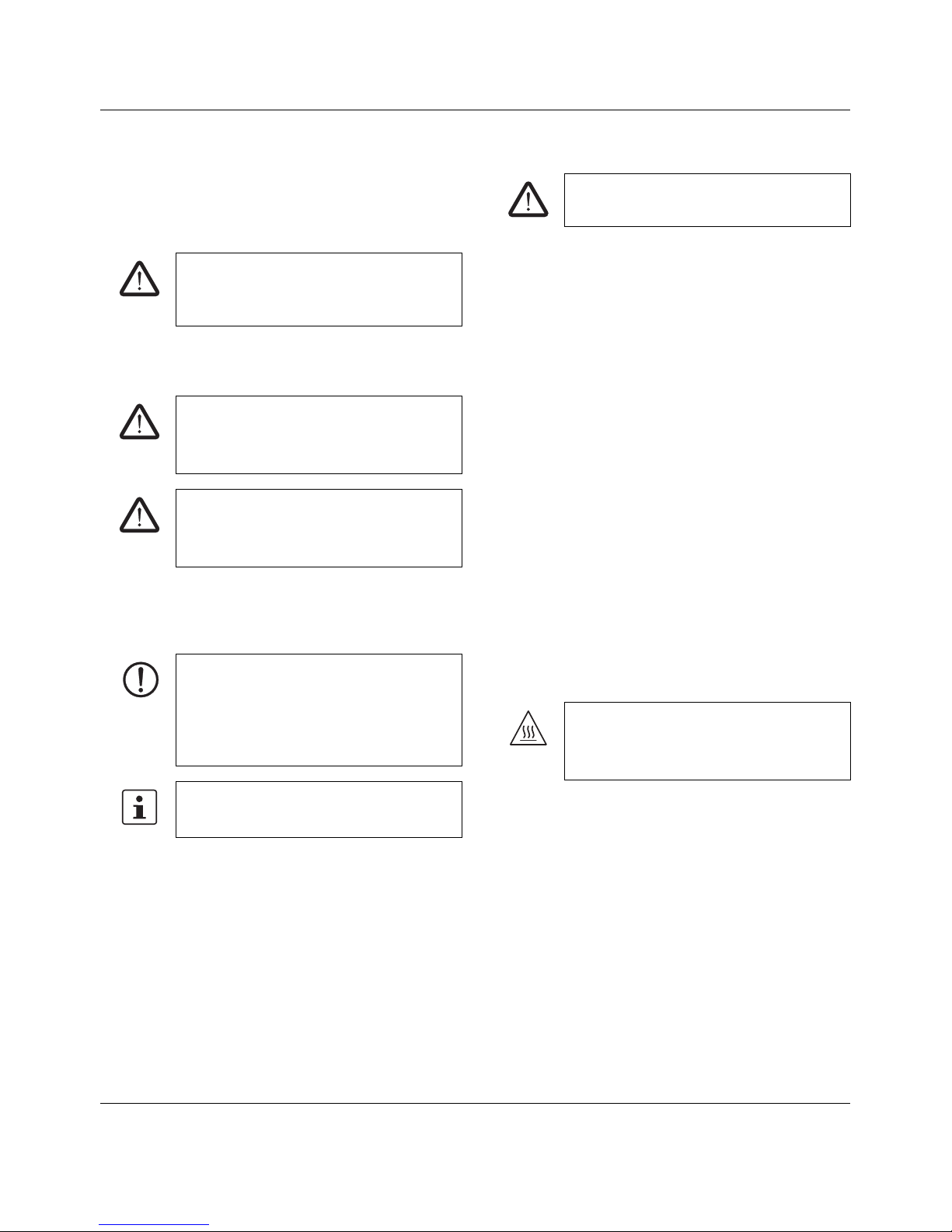
5.1 Symbols used
Instructions and possible hazards are indicated by
corresponding symbols in this document.
There are different categories of personal injury that are
indicated by a signal word.
The following symbols are used to indicate potential
damage, malfunctions, or more detailed sources of
information.
5.2 Safety and warning notes
– Only skilled persons may install, start up, and operate
the device.
– Never carry out work when voltage is present.
– Establish connection correctly and ensure protection
against electric shock.
– Connect the protective conductor device terminal block
with ground.
– Cover termination area after installation in order to avoid
accidental contact with live parts (e. g., installation in
control cabinet).
– This unit receives power from more than one source -
Disconnection of AC source and the energy storage is
required to de-energize this unit before servicing.
– Keep flames, embers or sparks away from the module.
– When connecting the batteries, observe the polarity and
do not short circuit the pole terminals.
– Provide a switch/circuit breaker close to the device at
the AC input, DC output and at the battery terminals,
which are labeled as the disconnecting device for this
device.
– Do not disconnect the fuse and/or battery connection
under hazardous location conditions.
– Use copper cables for operating temperatures of
75°C.
This is the safety alert symbol. It is used to
alert you to potential personal injury hazards.
Obey all safety measures that follow this
symbol to avoid possible personal injuries.
WARNING
This indicates a hazardous situation which, if
not avoided, could result in death or serious
injury.
CAUTION
This indicates a hazardous situation which, if
not avoided, could result in minor or moderate
injury.
NOTE
This symbol together with the signal word
NOTE and the accompanying text alert the
reader to a situation which may cause
damage or malfunction to the device,
hardware/software, or surrounding property.
This symbol and the accompanying text
provide the reader with additional information
or refer to detailed sources of information.
WARNING: Danger to life by electric
shock!
CAUTION: Hot surface
Depending on the ambient temperature and
load on the uninterruptible power supply, the
housing can become hot.


 Plus Startup manual")


