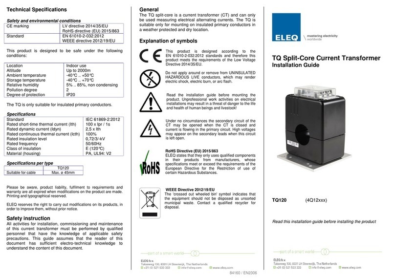
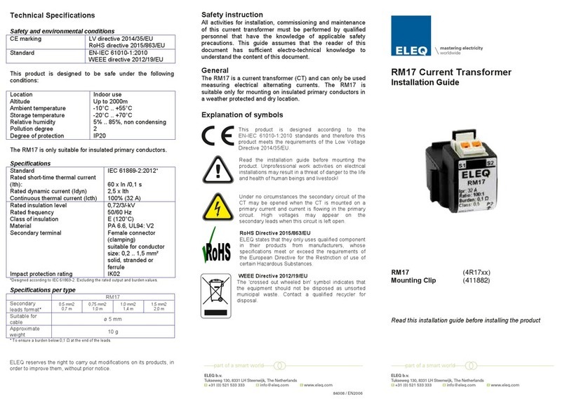
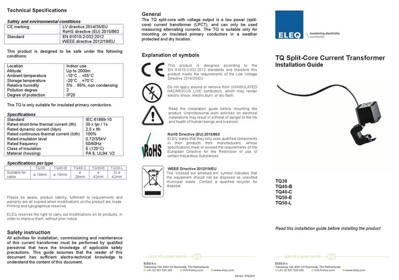
ELEQ TQ105 User manual

Technical Specifications
Safety and environmental conditions
CE marking
LV directive 2014/35/EU
RoHS directive (EU) 2015/863
Standard
EN 61010-2-032:2012
WEEE directive 2012/19/EU
This product is designed to be safe under the following
conditions:
Location
Altitude
Ambient temperature
Storage temperature
Relative humidity
Pollution degree
Degree of protection
Indoor use
Up to 2000m
-40°C .. +60°C
-20°C .. +70°C
5% .. 85%, non condensing
2
IP20
The TQ is only suitable for insulated primary conductors.
Specifications
Standard
Rated short-time thermal current (Ith)
Rated dynamic current (Idyn)
Rated continuous thermal current (Icth)
Rated insulation level
Rated frequency
Class of insulation
Material (housing)
IEC 61869-2:2012
60 x Ipr / 1s
2,5 x Ith
100%
0,72/3/-kV
50/60Hz
E (120°C)
PC,UL94:V2
Specifications per type
TQ105
no filling
TQ105
1 filling
TQ105
2 fillings
TQ105
3 fillings
Suitable
for cable
ø 31mm
ø 51mm
ø 71mm
ø 91mm
Please be aware, product liability, fulfilment to requirements and
warranty are all expired when modifications on the product are made.
Printing and typographical reserved.
ELEQ reserves the right to carry out modifications on its products, in
order to improve them, without prior notice.
Safety instruction
All activities for installation, commissioning and maintenance
of this current transformer must be performed by qualified
personnel that have the knowledge of applicable safety
precautions. This guide assumes that the reader of this
document has sufficient electro-technical knowledge to
understand the content of this document.
General
The TQ split-core is a current transformer (CT) and can only
be used measuring electrical alternating currents. The TQ is
suitable only for mounting on insulated primary conductors in
a weather protected and dry location.
Explanation of symbols
This product is designed according to the
EN 61010-2-032:2012 standards and therefore this
product meets the requirements of the Low Voltage
Directive 2014/35/EU.
Read the installation guide before mounting the
product. Unprofessional work activities on electrical
installations may result in a threat of danger to the life
and health of human beings and livestock!
Under no circumstances the secondary circuit of the
CT may be opened when the CT is closed and
current is flowing in the primary circuit. High voltages
may appear on the secondary leads when this circuit
is left open.
RoHS Directive (EU) 2015/863
ELEQ states that they only uses qualified components
in their products from ma
nufacturers, whose
specifications meet or exceed the requirements of the
European Directive for the Restriction of use of
certain Hazardous Substances.
WEEE Directive 2012/19/EU
The 'crossed out wheeled bin' symbol indicates that
the equipment should not be disposed as unsorted
municipal waste
. Contact a qualified recycler for
disposal.
TQ Split-Core Current Transformer
Installation Guide
TQ105 (4Q10xxx)
Read this installation guide before installing the product
84139 / EN2306
Technical Specifications
Safety and environmental conditions
CE marking
LV directive 2014/35/EU
RoHS directive (EU) 2015/863
Standard
EN 61010-2-032:2012
WEEE directive 2012/19/EU
This product is designed to be safe under the following
conditions:
Location
Altitude
Ambient temperature
Storage temperature
Relative humidity
Pollution degree
Degree of protection
Indoor use
Up to 2000m
-40°C .. +60°C
-20°C .. +70°C
5% .. 85%, non condensing
2
IP20
The TQ is only suitable for insulated primary conductors.
Specifications
Standard
Rated short-time thermal current (Ith)
Rated dynamic current (Idyn)
Rated continuous thermal current (Icth)
Rated insulation level
Rated frequency
Class of insulation
Material (housing)
IEC 61869-2:2012
60 x Ipr / 1s
2,5 x Ith
100%
0,72/3/-kV
50/60Hz
E (120°C)
PC,UL94:V2
Specifications per type
TQ105
no filling
TQ105
1 filling
TQ105
2 fillings
TQ105
3 fillings
Suitable
for cable
ø 31mm ø 51mm ø 71mm ø 91mm
Please be aware, product liability, fulfilment to requirements and
warranty are all expired when modifications on the product are made.
Printing and typographical reserved.
ELEQ reserves the right to carry out modifications on its products, in
order to improve them, without prior notice.
Safety instruction
All activities for installation, commissioning and maintenance
of this current transformer must be performed by qualified
personnel that have the knowledge of applicable safety
precautions. This guide assumes that the reader of this
document has sufficient electro-technical knowledge to
understand the content of this document.
General
The TQ split-core is a current transformer (CT) and can only
be used measuring electrical alternating currents. The TQ is
suitable only for mounting on insulated primary conductors in
a weather protected and dry location.
Explanation of symbols
This product is designed according to the
EN 61010-2-032:2012 standards and therefore this
product meets the requirements of the Low Voltage
Directive 2014/35/EU.
Read the installation guide before mounting the
product. Unprofessional work activities on electrical
installations may result in a threat of danger to the life
and health of human beings and livestock!
Under no circumstances the secondary circuit of the
CT may be opened when the CT is closed and
current is flowing in the primary circuit. High voltages
may appear on the secondary leads when this circuit
is left open.
RoHS Directive (EU) 2015/863
ELEQ states that they only uses qualified components
in their products from manufacturers, whose
specifications meet or exceed the requirements of the
European Directive for the Restriction of use of
certain Hazardous Substances.
WEEE Directive 2012/19/EU
The 'crossed out wheeled bin' symbol indicates that
the equipment should not be disposed as unsorted
municipal waste. Contact a qualified recycler for
disposal.
TQ Split-Core Current Transformer
Installation Guide
TQ105 (4Q10xxx)
Read this installation guide before installing the product
84139 / EN2306
Technical Specifications
Safety and environmental conditions
CE marking
LV directive 2014/35/EU
RoHS directive (EU) 2015/863
Standard
EN 61010-2-032:2012
WEEE directive 2012/19/EU
This product is designed to be safe under the following
conditions:
Location
Altitude
Ambient temperature
Storage temperature
Relative humidity
Pollution degree
Degree of protection
Indoor use
Up to 2000m
-40°C .. +60°C
-20°C .. +70°C
5% .. 85%, non condensing
2
IP20
The TQ is only suitable for insulated primary conductors.
Specifications
Standard
Rated short-time thermal current (Ith)
Rated dynamic current (Idyn)
Rated continuous thermal current (Icth)
Rated insulation level
Rated frequency
Class of insulation
Material (housing)
IEC 61869-2:2012
60 x Ipr / 1s
2,5 x Ith
100%
0,72/3/-kV
50/60Hz
E (120°C)
PC,UL94:V2
Specifications per type
TQ105
no filling
TQ105
1 filling
TQ105
2 fillings
TQ105
3 fillings
Suitable
for cable
ø 31mm
ø 51mm
ø 71mm
ø 91mm
Please be aware, product liability, fulfilment to requirements and
warranty are all expired when modifications on the product are made.
Printing and typographical reserved.
ELEQ reserves the right to carry out modifications on its products, in
order to improve them, without prior notice.
Safety instruction
All activities for installation, commissioning and maintenance
of this current transformer must be performed by qualified
personnel that have the knowledge of applicable safety
precautions. This guide assumes that the reader of this
document has sufficient electro-technical knowledge to
understand the content of this document.
General
The TQ split-core is a current transformer (CT) and can only
be used measuring electrical alternating currents. The TQ is
suitable only for mounting on insulated primary conductors in
a weather protected and dry location.
Explanation of symbols
This product is designed according to the
EN 61010-2-032:2012 standards and therefore this
product meets the requirements of the Low Voltage
Directive 2014/35/EU.
Read the installation guide before mounting the
product. Unprofessional work activities on electrical
installations may result in a threat of danger to the life
and health of human beings and livestock!
Under no circumstances the secondary circuit of the
CT may be opened when the CT is closed and
current is flowing in the primary circuit. High voltages
may appear on the secondary leads when this circuit
is left open.
RoHS Directive (EU) 2015/863
ELEQ states that they only uses qualified components
in their products from manufacturers, whose
specifications meet or exceed the requirements of the
European Directive for the Restriction of use of
certain Hazardous Substances.
WEEE Directive 2012/19/EU
The 'crossed out wheeled bin' symbol indicates that
the equipment should not be disposed as unsorted
municipal waste. Contact a qualified recycler for
disposal.
TQ Split-Core Current Transformer
Installation Guide
TQ105 (4Q10xxx)
Read this installation guide before installing the product
84139 / EN2306
84139 / EN2306
ELEQ b.v.
Tukseweg 130, 8331 LH Steenwijk, The Netherlands
ELEQ b.v.
Tukseweg 130, 8331 LH Steenwijk, The Netherlands

Always avoid working on live parts of an installation.
Mounting instruction
In order to mount this CT 4 spring fitted screws need to be
placed and tightened with a M5 Hex / Allen key.
Assembly
Under no circumstances the secondary circuit of the CT may
be opened when the CT is closed and the current is flowing in
the primary circuit. High voltages may appear on the
secondary leads when this circuit is left open.
1. Ensure a safe working area during assembly,
maintenance and inspection of the CT. If necessary,
disconnect the power of the primary circuit and make sure
it can not be enabled unintentionally.
2. Find the power direction of the primary. It is recommended
to mount the P1 side to power source and the P2 side to
power consumer. If the CT is installed like this, the arrow
on the CT will indicate the direction of the power flow.
3. Connect the secondary leads (S1, S2) to the TQ
terminals. Ensure that the leads are capable of carrying
the current output of the CT.
4. Connect the secondary leads (S1, S2) to the low
impedance current input of the measurement instrument
(e.g., an ammeter or current input of kWh-meter).
5. To mount the CT, use the Allen key to securely fasten the
screws in a crisscross pattern.
6. Enable the primary circuit if necessary.
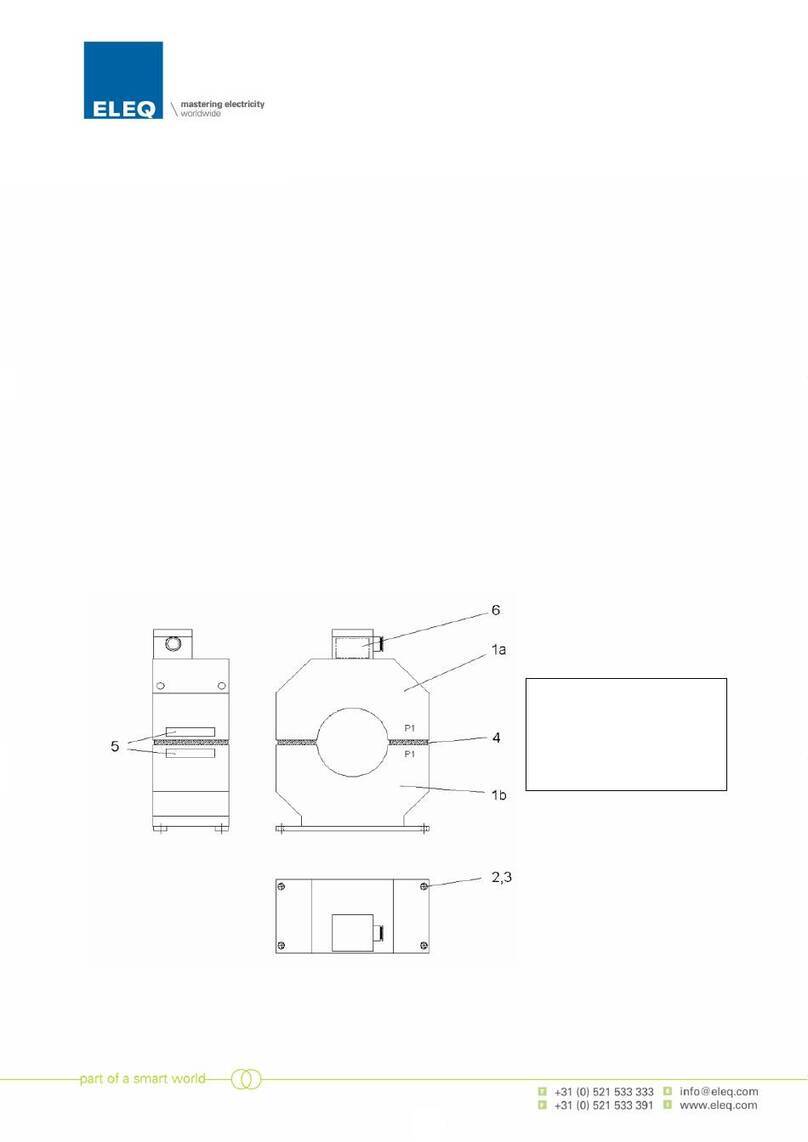
Wiring Diagram
Maintenance and inspection
Check whether the secondary leads are connected firmly.
Check whether the CT is closed properly.
Check whether the CT is mounted firmly.
Remove severe pollution on the casing. Contact with
moisture, especially with the core, must be avoided.
Attention
Do not touch the core surfaces by hand: skin acid may
damage the core.
Temporarily disconnecting the CT
The secondary leads of the CT always have to be connected
to a low impedance burden such as an ammeter. When
during maintenance, no burden is available to connect to, the
secondary leads of the CT (the two secondary terminals)
must be short-circuited. Before changing the secondary circuit
the CT core shall be opened.
Problem solving
e.g. unexpected values or incorrect values , reversed power,
Check the settings of the meter by using the installation
guide of the meter.
Check whether the CT is mounted on the intended cable in
the right direction.
Check if the CT is closed properly.
Check the value of the secondary burden (secondary leads
length/diameter and meter impedance). See product/data
sheet for the maximum burden value.
If previous points did not solve the problem:
Check carefully whether there is dust or other pollution
present between the two parts of the core. In case there is
pollution, the core surfaces can be cleaned with a lint free
cloth and then protected with an extremely thin layer of acid
free petroleum jelly (Vaseline).
Attention
Always follow the disassembling instructions when reversing
the CT.
Disassembly instruction
1. Ensure a safe working area during disassembling the CT.
If necessary, disconnect the power of the primary circuit
and make sure it cannot be enabled unintentionally.
2. Open the CT by removing the screws.
3. Disconnect the secondary leads from the measurement
instrument.
4. Disconnect the secondary leads from the meter.
5. Enable the primary circuit if is necessary.
Recycling
When the product has reached ‘end of life’, it must be
recycled. Do not dispose this product as unsorted municipal
waste. Contact a qualified recycler for disposal.
Other ELEQ Transformer manuals
Popular Transformer manuals by other brands
Heitronic
Heitronic 20140 Installation and operating instructions
Valcom
Valcom VMT-1 Product guide
VOLTCRAFT
VOLTCRAFT SPAS-2100 operating instructions
Intermatic
Intermatic PX600 Installation, operation & service manual

Sea gull lighting
Sea gull lighting AMBIANCE 98743S installation instructions

Huawei
Huawei STS-3000K-H1 installation guide
Hameg
Hameg HM6050-2 manual
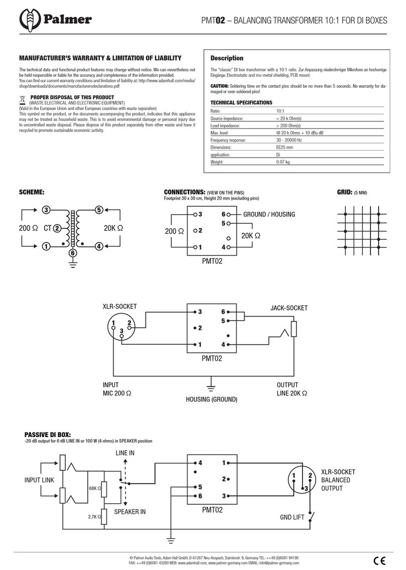
Palmer
Palmer PMT02 manual
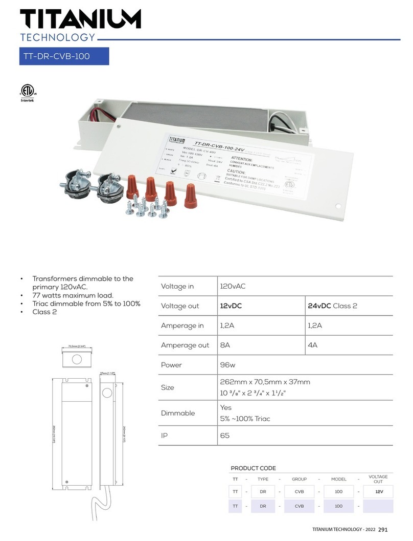
Titanium
Titanium TT-DR-CVB-100 manual
Federal Signal Corporation
Federal Signal Corporation 2001-AC Description, Specifications, Installation, Operation, and Service Manual
philippi
philippi RTR Series instruction manual
Tektronix
Tektronix CT-4 instruction manual


