Tektronix CT-4 User manual

Instruction Manual
CT-4
High-Current Transformer
070-6478-02

Copyright Tektronix, Inc. 1987. All rights reserved.
Tektronix products are covered by U.S. and foreign patents, issued and
pending. Information in this publication supercedes that in all previously
published material. Specifications and price change privileges reserved.
Printed in the U.S.A.
Tektronix, Inc., P.O. Box 1000, Wilsonville, OR 97070–1000
TEKTRONIX and TEK are registered trademarks of Tektronix, Inc.

WARRANTY
Tektronix warrants that the products that it manufactures and sells will be free from defects
in materials and workmanship for a period of one (1) year from the date of shipment. If a
product proves defective during this warranty period, Tektronix, at its option, either will
repair the defective product without charge for parts and labor, or will provide a
replacement in exchange for the defective product.
In order to obtain service under this warranty, Customer must notify Tektronix of the
defect before the expiration of the warranty period and make suitable arrangements for the
performance of service. Customer shall be responsible for packaging and shipping the
defective product to the service center designated by Tektronix, with shipping charges
prepaid. Tektronix shall pay for the return of the product to Customer if the shipment is to
a location within the country in which the Tektronix service center is located. Customer
shall be responsible for paying all shipping charges, duties, taxes, and any other charges for
products returned to any other locations.
This warranty shall not apply to any defect, failure or damage caused by improper use or
improper or inadequate maintenance and care. Tektronix shall not be obligated to furnish
service under this warranty a) to repair damage resulting from attempts by personnel other
than Tektronix representatives to install, repair or service the product; b) to repair damage
resulting from improper use or connection to incompatible equipment; c) to repair any
damage or malfunction caused by the use of non-Tektronix supplies; or d) to service a
product that has been modified or integrated with other products when the effect of such
modification or integration increases the time or difficulty of servicing the product.
THIS WARRANTY IS GIVEN BY TEKTRONIX IN LIEU OF ANY OTHER
WARRANTIES, EXPRESS OR IMPLIED. TEKTRONIX AND ITS VENDORS
DISCLAIM ANY IMPLIED WARRANTIES OF MERCHANTABILITY OR
FITNESS FOR A PARTICULAR PURPOSE. TEKTRONIX’ RESPONSIBILITY
TO REPAIR OR REPLACE DEFECTIVE PRODUCTS IS THE SOLE AND
EXCLUSIVE REMEDY PROVIDED TO THE CUSTOMER FOR BREACH OF
THIS WARRANTY. TEKTRONIX AND ITS VENDORS WILL NOT BE LIABLE
FOR ANY INDIRECT, SPECIAL, INCIDENTAL, OR CONSEQUENTIAL
DAMAGES IRRESPECTIVE OF WHETHER TEKTRONIX OR THE VENDOR
HAS ADVANCE NOTICE OF THE POSSIBILITY OF SUCH DAMAGES.

Optional DC Bucking Coil
5Ć4
Optional Accessories 5Ć4

Optiona DC Bucking Coi Assemb y
5Ć3
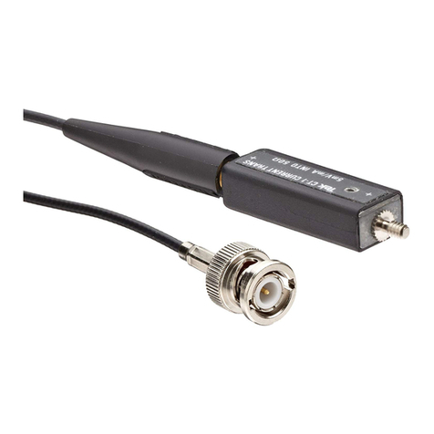
The CTĆ4 with current probe attached
peaksinewavewithA6302/A6302XL/A6312/TCP202inthe1000:1receptac e
Maximum pu se amp itude versus duration, A6302/A6302XL/A6312 in 1000:1
Maximum pu se amp itude versus duration, A6302/A6302XL/A6312 in 20:1
Typica response of the CTĆ4 with the A6302/AM503B to a owĆfrequency
square wave


The core and sh eld assembly s nsulated from the w nd ngs and the handle, allow ng
measurements on bare conductors w th potent als to 3000 volts. The h ghĆvoltage nsulaĆ
t on accessory may be used to extend the allowable voltage by several t mes. The opt onal
DC Buck ng Co l (015Ć0190Ć00), wh ch sl ps over the front of the CTĆ4, null f es the saturat ng
effects of steadyĆstate dc currents to 300 amperes.
The CTĆ4 H gh Current Transformer s des gned to extend the current measur ng capaĆ
b l ty of the Tektron x A6302, A6302XL, A6312, TCP202, and P6021 Current Probes. The
CTĆ4 extends the measurement range up to 1000 t mes.
The CTĆ4 ncludes a p stolĆgr p handle w th two receptacles to accept the current probe
n e ther the 1000:1 or 20:1 current ranges. A sl d ng jaw on the transformer perm ts nsert on
of the currentĆcarry ng conductor w thout break ng the c rcu t under test.


Bandwidth (-3 dB) with
17.5 ns (calculat d from
bandwidth)
A6302XL and AM503B
or AM5030
0.5 Hz to 17 MHz
Curr nt Rang s with
A6312/A6302/A6302XL and
AM503/A/B or AM5030
20:1 R c ptacl
2,000 A p akĆtoĆp ak
at 1 kHz (sin wav ).
TCP202/A6312/A6302/
A6302XL and optional
DC Bucking Coil
Th l ctrical charact ristics list d in Tabl 1Ć1 ar valid wh n th CTĆ4 is us d with a caliĆ
brat d oscilloscop and a calibrat d A6312/A6302/A6302XL curr nt prob with th
AM503X amplifi r, TCP202 curr nt prob , or P6021 curr nt prob . Th instrum nts must
b op rat d within th nvironm ntal limitations stat d in Tabl 1Ć3.
120 Hz to 20 MHz
Transi nt R spons
1Hzto1MHz
P6021
20 mA to 100 A/div
1000:1 R c ptacl 1 A/div to 5,000 A/div
0.5 Hz to 20 MHz
1000:1 R c ptacl 10 A/div to 5,000 A/div
20:1 R c ptacl 200 mA/div to 100 A/div
1000:1 R c ptacl 1 A/div to 1,000 A/div
20:1 R c ptacl 20 mA/div to 20 A/div
P6021
TCP202
TCP202 or A6302/A6312
and AM503X

included
(op ional)
20,000 A peak, no o
exceed 50% du y fac or
1,000 V CAT III wi h
uninsula ed conduc or
3,000 V peak, < 11% du y
fac or, < 100 msec period

CTĆ4 With Optional DC
(optional)

To 15,240 m (50,000 ft)
2,000 m (6,562 ft) 1,000 V CAT III
4,572 m (15,000 ft) 600 V CAT III or 1,000 V CAT II
Altitude
NonĆOper ting
Oper ting
EC Decl r tion of
Conformity - Low
Volt ge
Compli nce w s demonstr ted to the following specifiĆ
c tion s listed in the Offici l Journ l of the Europe n
Communities:
Low Volt ge Directive 73/23/EEC s mended by
93/68/EEC.
EN 61010Ć1:1993/A2
S fety requirements for electric l equipment for
me surement, control, nd l bor tory use.
EN 61010Ć2Ć032:1995
P rticul r requirements for h ndĆheld current
cl mps for electric l me surements nd test.

The CTĆ4 High Current Trans ormer may be used with the A6312, A6302 or A6302XLa
Current Probes and the AM 503/A/Bbor AM 5030cCurrent Probe Ampli iers. The CTĆ4 can
also be used with the TCP202 AC/DC Current Probe or the P6021 AC Current Probe. Some
o the electrical characteristics are di erent depending on the current probe you select (see
page 1Ć1).
aA6302XL is o ly compatible with AM 503B or AM 5030 amplifiers.
bAM 503/A/B requires a TM 500 or TM 5000 Series Power Module Mai frame.
cAM 5030 requires a TM 5000 Series Power Module Mai frame.
Fig. 2Ć1. The CTĆ4 with curre t probe attached.
At the rear o the CTĆ4 are two probe receptacles or two di erent current ranges. The
A6302, or example, has a current range o 20 mA/div to 100 A/div in the 20:1 receptacle
(assuming the current probe normal range is 1 mA/div to 5 A/div) and 1 A/div to 5,000 A/div
in the 1000:1 receptacle. See Fig. 2Ć1.

The DC Bucking Coil is an optional accessory to the CTĆ4.
Install the current probe in the CTĆ4 as follows:
1. Degauss the probe (if so equipped).
2. Select the appropriate receptacle based on the anticipated current magnitude.
3. Open the thumbĆcontrolled probe slider, insert the probe into the selected receptacle,
and hook the probe aw over the enclosed conductor.
4. Press the probe slider fully forward to ensure that the core is closed. See Fig. 2Ć1. AlĆ
ways insert the current probe so that the probe slider faces outward from the CTĆ4. This
will ensure correct current polarity.
#! ! & ! ! $ "! "
! ! ! ! ( & ! "! % $ ! ! ( %"
!
! $ ! ( ! ! !" "! $ ! $
! "! "! ! "%
""! !"!("!!!'(
% ! (
The CTĆ4 is insulated to withstand bare test conductor voltages to 1000 V CAT III (3000
V peak). For measurements on conductors at higher voltages, a length of highĆvoltage inĆ
sulation is provided. This insulation should be wrapped around the test conductor at the
test point before attaching the CTĆ4. To ensure protection, the insulation should be wrapped
around the conductor at least three turns or a minimum insulation length of six inches. The


length supplied as a standard accessory will provide approximately three layers when
wrapped around the largest conductor that the CTĆ4 will accept. Center the CTĆ4 on at least
a sixĆinch width of insulation.
Do not use damaged insulation wrap.

Fig. 2Ć4 shows the maximum recommended measurement duration for a 1000 A eakĆ
toĆ eak sinewave with the A6302, A6302XL, A6312, or TCP202 on the 1000:1 rece tacle.
Figs. 2Ć5 and 2Ć6 are derating curves for the P6021.
Fig. 2Ć4 . Maximum recommended measurement duration for a 1000 A eak sinewave with the
A6302, A6302XL, A6312, or TCP202 in the 1000:1 rece tacle.

The max mum pulse current that can be measured us ng the CTĆ4 s l m ted by
transformer core saturat on. F gs. 2Ć7 and 2Ć8 are graphs of max mum pulse ampl tude
versus durat on for the A6302, A6302XL, A6312, and TCP202. The ampĆsecond product
spec f cat on prov des a bas s for calculat ng the current l m tat on w th any g ven pulse
w dth. Although the CTĆ4 has an ampĆsecond product of 5 ampere seconds, the real l m t
s that of the assoc ated current probe. The ampĆsecond products of the probes are l sted
n the Character st cs" sect on of the probe manuals.
For example, us ng the CTĆ4 1000:1 receptacle, the probe ampĆsecond rat ng s
mult pl ed by 1000. In the case of the A6302/A6302XL/A6312, wh ch has an ampĆsecond
rat ng of 100 AĆs, the system ampĆsecond rat ng would be 0.1 ampĆseconds. An example
of apply ng th s spec f cat on follows:
Problem: Calculate the max mum pulse w dth for the CTĆ4 w th an A6302,
A6302XL, or A6312 current probe for a current pulse of 1,000 A peak.
Table of contents
Other Tektronix Transformer manuals