elero RevoLine M RolTop M6 User manual

RolTop Roller Blind Drive
138133301_EN_1116
RolTop Roller Blind Drive
13 Operating and installation instructions
Please keep these operating instructions for later use, to be
available throughout the life of the product!
The German manual is the original version.
All other documents represent the language translations of
the original text.
All rights in the case of a patent, utility model or ornamental
design registration are reserved.
14 General for instructions
The content structure is based on the life cycles of the elec-
tric motor drive (hereinafter referred to as "Product").
The manufacturer reserves the right to make changes to
the Specications stated in these Operating Instructions
at any time. These may, in individual cases, be dierent
from the respective product version, however the functional
information will not undergo signicant changes or become
invalid. The current version of the Specications may be
requested from the manufacturer at any time. No claims
may be asserted against the manufacturer as a result of the
preceding sentence. Deviations from text or picture state-
ments are possible and depend on the technical develop-
ment, features, and accessories of the products. Deviating
information on special versions will be explained by the
manufacturer in the sales documentation. Other information
shall remain unaected by these provisions.
14.1 Standards and Directives
During the design process, the basic health and safety
requirements of the applicable laws, Standards and Direc-
tives were complied with. The safety is conrmed by the
declaration of conformity (see "Declaration of Conformity").
All safety information in these Operating Instructions refer
to the laws and regulations currently applicable in Germany.
All instructions in the Operating Instructions shall be ob-
served without limitation and at any time. Beside the safety
instructions contained in these Operating Instructions, the
provisions for accident prevention, environmental protection
and occupational safety, which are applicable for the oper-
ating site, must be observed. Provisions and Standards for
the safety rating can be found in the Declaration of Con-
formity
Table Of Contents
13 Operating and installation instructions 1
14 General for instructions 1
14.1 Standards and Directives 1
14.2 Intended use 1
14.3 Foreseeable misuse 2
14.4 Warranty and liability 2
14.5 Customer service of the manufacturer 2
15 Safety 2
15.1 General safety instructions 2
15.2 Layout of the safety guidelines 2
16 Product description 3
17 Assembly 3
17.1 Mechanical fastening 3
17.2 Electrical connection 4
17.3 Connection example, RolTop 230 V/50 Hz 4
17.4 Parallel connection 4
17.5 Commissioning 4
17.6 Setting the end positions and the relief 4
17.6.1 Relief function for the end position(s) 5
17.6.2 Relief function at the upper stop 5
17.6.3 Relief function at the lower stop 5
17.6.4 Changing / Deleting the limit positions
and deleting the discharge function 5
17.6.5 Four variants of end position settings 5
17.6.6 Variant A: Upper and lower end position freely adjust-
able 5
17.6.7 Variant B: Fixed upper limit stop / lower
end position freely adjustable 6
17.6.8 Variant C: Fixed upper and lower limit stop 6
17.6.9 Variant D: Upper end position freely
adjustable, xed lower limit stop 6
18 Troubleshooting 6
19 Repair 7
20 Repair 7
21 Manufacturer's address 7
22 Disassembly and disposal 7
23 Conformity Declaration 7
24 Technical data and dimensions 7
24.1 RevoLine M 8
24.2 RevoLine S 9
24.3 RevoLine M RH 10
24.4 RevoLine L 10

15 Safety
15.1 General safety instructions
The general safety notes when using pipe drives can be
found in the leaet "Instructions on safety" that is enclosed
with each drive"(leaet item no. 138200001). These operat-
ing instructions contain all the safety instructions that must
be observed in order prevent and eliminate hazards in the
handling of the product in the individual life cycles. The safe
operation of the product can only be ensured when all given
safety instructions are observed.
15.2 Layout of the safety guidelines
The safety instructions in this document are identied by
hazard signs and safety symbols and are designed accord-
ing to the SAFE principle. They contain information on the
nature and source of the danger of possible consequences
and to prevent the danger.
The following table denes the representation and descrip-
tion of hazard levels with possible personal injury, as used
in this manual.
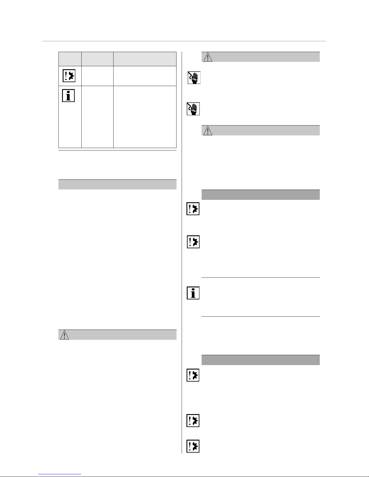
Symbol
Signal
word
Meaning
DANGER Warns before an acci-
dent, which will result if
instructions are not fol-
lowed, which can lead to
life-threatening, irreversi-
ble injury or death.
WARNING Warns before an acci-
dent, which can happen
if the instructions are not
followed, which can lead
to serious, possibly fatal,
irreversible injury or death.
CAUTION Warns before an accident,
which can happen if the
instructions are not fol-
lowed, which may lead to
minor reversible injury.
Fig. 1 Notation of personal injury
The following table describes the icons used in these op-
erating instructions that are used for imaging of the dan-
gerous situation in connection with the symbol of the threat
level.
Symbol
Meaning
Danger of electric voltage, electric
shock:
This symbol indicates a risk of electric
shock.
Fig. 2 Notation-specic hazard
The following table denes the representation used in the
operating instructions and description of situations where
damage can occur to the product or refers to important
facts, conditions, tips and information.
2 | EN © elero GmbH
Warranty and liability | Safety
14.2 Intended use
The product is intended for use in façade engineering to
drive electrically powered sun protection devices.
The determining factor for the drive is the elero drive com-
putation program (http://elero.de/
antriebsberechnungsprogramm).
Further elds of application have to be arranged with the
manufacturer, elero GmbH Antriebstechnik (see Address).
The operator will be solely responsible for damages result-
ing from improper use of the product. The manufacturer
cannot be held liable for personal or material damages
caused by misuse or procedural errors, and by improper
operation and commissioning.
The product may be operated only by trained and author-
ized personnel under observance of all safety.
Only if used according to the specications of these operat-
ing and installation instructions for the safe and proper use
and safe operation of the product are guaranteed.
Intended use includes the observance and compliance with
all safety instructions with regards to this operating manual
and all applicable regulations, and professional associations
of applicable laws for environmental protection. Intended
use includes the observance of prescribed operating rules
in these operating and installation instructions.
14.3 Foreseeable misuse
A use which deviates from the intended use stated by the
manufacturer, elero GmbH Antriebstechnik (see "Address"),
is deemed as foreseeable misuse.
14.4 Warranty and liability
Principally, the General Terms and Conditions of the man-
ufacturer, elero GmbH Antriebstechnik (see "Address"),
apply. The terms and conditions are part of the sales
documents and handed over to the operator upon deliv-
ery. Liability claims for personal or material damages are
excluded when they can be attributed to one or more of the
following causes:
• Opening of the product by the customer
• Unintended use of the product
• Improper installation, commissioning, or operation of the
product
• Structural modications to the product without the written
consent of the manufacturer
• Operation of the product with improperly installed con-
nections, defective safety devices or improperly installed
safeguards
• Non-observance of the safety provisions and instructions
of these Operating Instructions
• Non-compliance with the technical data
14.5 Customer service of the manufacturer
The product should only be repaired by the manufacturer
in case of a failure. The address for sending to customer
service, see the chapter "Address".
If you have not purchased the product directly from elero,
please contact the supplier of the product.
Symbol Signal
word
Meaning
NOTE This symbol warns of a
possible property dam-
age.
Important: This symbol points out
important facts and con-
ditions as well as to addi-
tional information in these
operating and installation
instructions. It also refers
to certain statements that
give additional information
or help you perform a task
easily.
Fig. 3 Notation of property damage as well as additional
information
The following example represents the basic structure of a
safety warning:
SIGNAL WORD
Type and source of danger
Explanation of the type and source of the danger
►Measures to prevent the danger.
16 Product description
The RolTop is an electromechanical tubular motor drive. It
performs parallel axial movements.
Commissioning of the RolTop with elero assembly cable
for setting dierent functions.
Venetian blind with free ride (torque deactivation)
Relief function for the Venetian blind (Venetian blind
protection).
• The variant-dependent values of your RolTop can be
removed from the type label.
• The dierent versions of the RolTop contain dierent
types of brake systems depending on size and torque.
The result may yield dierent performance e.g. regarding
access to end positions.
17 Assembly
CAUTION
Personal injury from hot surfaces.
Drive heats up during operation, the drive housing can be
hot. Possible burning of the skin.
►Wear personal protective equipment (gloves).
Triggered by a possible material errors may occur or
impact shock and injury due to a gearbox break, bud break
or a clutch defect.
►Suitable materials are to be used for the construction as
well as perform a sampling inspection by double load test
according to DIN EN 60335-2-97.
Risk of injury due to impact or shock caused by not prop-
erly mounted or latched motor bearings. Hazards caused
by insufficient stability or stability and stored energy (grav-
ity).
►Selection of engine bearing torque specications.
►Drive must be backed up with all attached backup devices.
►Check for proper latching on engine mounts and correct
tightening torques.
WARNING
Danger of injury due to electric current.
Electric shock possible.
►Electrical work can only be performed by an authorized
electrician.
Danger of injury due to electric current.
Hazardous possibly by parts that have become live in the
error state.
►Electrical connection is described in the operating and
installation instructions including cable bushing.
CAUTION
Risk of injury due to malfunctions due to improper installa-
tion.
Driven by winds and possibly destroyed parts of the appli-
cation.
►For safe operation, the end positions must be set / pro-
grammed.
►Training program of the manufacturer for specialist com-
panies.
NOTE
Loss of power supply, termination of machine parts and
other malfunctions.
►For safe operation, no false mount must be made and the
end position settings must be carried out during commis-
sioning.
Damage to the RolTop due to moisture penetration.
►For devices with protection class IP44, the ends of all
cables or connectors must be protected against the
ingress of moisture. This measure must be implemented
immediately after removal of the RolTop from the original
packaging.
►The drive may only be installed so that it is not irrigated.
Important
In the delivery status (factory setting), the RolTop in com-
missioning mode.
►You have to set the end positions (see chapter 5.6).
17.1 Mechanical fastening
Important preliminary consideration:
The working space around the built-in drive is usually very
small. Therefore, before the mechanical installation provide
an overview of the implementation of the electrical connec-
tion (see Section 5.2) and make any necessary changes
right away.
NOTE
Damage to the electrical wiring by squeezing or tensile
loading.
►Route all electrical cables so that they are not subjected
to crushing or tensile load.
►Note the bending radius of the cables (at least 50 mm).
►Lay the connection cable in a loop downwards to prevent
water running into the drive.
Damage to the drive by the action of impact forces.
►Insert the drive into the shaft, never thrust the drive into
the shaft or smash onto the drive!
►Never allow the drive to fall!
Damage or destruction of the drive by drilling.
►Never drill into the drive!
© elero GmbH EN | 3
Product description | Assembly (mechanical attachment)
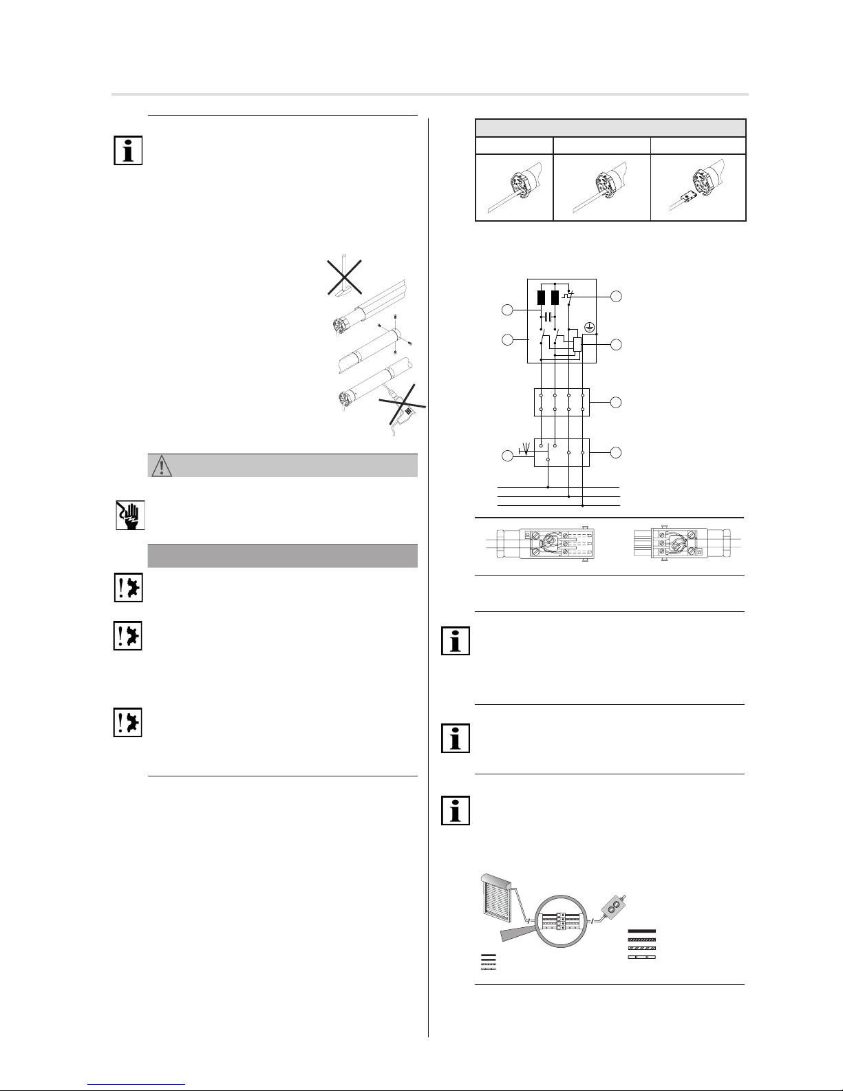
Removal and insertion of the device plug
Delivery status Remove plug Insert plug
Fig. 4 Removal and insertion of the device plug
17.3 Connection example, RolTop 230 V/50 Hz
PE
N
L1
102
sw
br
bl
gr/ge
1
2
3
4
7
6
Wicklungsthermostat
Geräteschalter
Abzweigdose
Schalterdose
Jalousieschalter/Jalousietaster
Elektronik
Kondensator
sw schwarz
br braun
bl blau
gr/ge grün/gelb
L1,N,PE Netz 230V/50Hz
1
2
3
4
5
6
5
7
3
2
1
3
2
1
Fig. 5 Circuit diagram RolTop 230 V / 50 Hz and
wiring when used with Hirschmann plug STAS 3
Important
The motor control must be interlocked in up / down direc-
tion.
A reversing delay of at least 0,5 seconds must be ensured.
17.4 Parallel connection
Important
You can connect several parallel RolTop. Note the maxi-
mum switching capacity of switching.
17.5 Commissioning
Important
The drive is in the delivery in commissioning mode.
►You have to set the end positions with the elero assem-
bly cable.
►Connection of the assembly cable is only admissible for
commissioning of the drive and the setting processes.
%ODX1HXWUDOOHLWHU
6FKZDU]
%UDXQ
*UQJHOE
HOHUR
%ODX1HXWUDOOHLWHU
6FKZDU]
%UDXQ
*UQJHOE
Fig. 6 Connection for cable assembly
►Switch on mains.
►You can now set the end positions with the elero assem-
bly cable.
→
1
→
2
→
3
1Winding thermostat
2Appliance switch
3Junction box
4Switch box
5Blind switches/
blind push buttons
6Electronics
7Capacitor
sw black
br brown
bl blue
gr/ge green yellow
4 | EN © elero GmbH
Assembly (Electrical connection) | Commissioning
Important
Attach the RolTop only at the appropriate fasteners.
Permanently installed control devices shall be clearly dis-
played.
• The curtain must be fastened to the winding shaft.
• The prole tube must have enough distance to the motor
tube.
• Look for an axial clearance (1-2 mm).
Installation in prole tubes
ⒶInsert the drive with a suitable adapt-
er and traction ring into the prole
tube.
Lay the motor cable protected in or-
der to prevent damage by the driven
component.
ⒷSecure the counter bearings against
axial displacement, e.g. screw shaft
spider or rivet.
Secure drive in axial storage!
ⒸSecure hanging on the shaft!
17.2 Electrical connection
WARNING
Danger to life due to faulty electrical connection.
Electric shock possible.
►Before commissioning check the correct connection of
the PE conductor.
NOTE
Damage to the RolTop by faulty electrical connection.
►Before commissioning check the correct connection of
the PE conductor.
Damage or destruction of RolTop by the penetration of
moisture.
►For units with protection class IP 44, the customer con-
nection of the cable ends or connector (cable bushing)
must also be carried out in accordance with protection
class IP 44.
Damage or destruction of RolTop for variants with 230 V
AC 1 due to faulty control.
►Switch with OFF setting (Dead man) for drives must be
installed within sight of the RolTop, but away from any
moving parts and amounting to about 1.5 m.
Important
For electric connection no transmission and retransmission
of the access line or connector is required as a rule.
Depending upon used mounting plate and/or adapter plate
it is necessary in particular with the RolTop Type S to
remove this screwed plate before a cable exchange.
Connection only in free of tension status, in addition
drive line without tension
1 Using a suitable screwdriver, press out the lock of the
device connector to the line.
2Disconnect the plug.
3Insert connector until the latch engages.
17.6 Setting the end positions and the relief
Important preliminary consideration:
Decide on a specic relief function before setting the end
positions (dierent combination options according to the
following statements):
This will save unnecessary setting eort!
Press the travel key until the drive signals the transition into
the setting mode, by a short automatic stop. You can now
program the end positions. After setting the two end posi-
tions, the setting mode is completed.
17.6.1Relief function for the end position(s)
If an end position is set to stop, an additional relief for the
Venetian blind can be released.
Important
Activation of the relief function (in the versions B to D) takes
place in one work step when the end positions are pro-
grammed (see chapter 5.6.7 to chapter 5.6.9)!
17.6.2Relief function at the upper stop
For variant C (see chapter 5.6.7)
and variant D (see chapter 5.6.8):
Activate relief function at the upper stop.
1 Push and hold the UP button ▲ from instruction ①
(chapters 5.6.7 and 5.6.8) and actuate the DOWN
button ▼ with the assembly cable (at the same time).
Keep both buttons pushed until the Venetian blind
stops.
The relief function at the upper stop is activated.
17.6.3Relief function at the lower stop
For version C (see chapter 5.6.8)
and version D (see chapter 5.6.9):
Activate relief function at the lower stop
1 Push and hold the DOWNP button ▼ from instruction
③(chapters 5.6.8 and 5.6.9) and actuate the UP
button ▲ with the assembly cable (at the same time).
Keep both buttons pushed until the Venetian blind
stops.
The relief function at the lower stop is activated.
17.6.4Changing / Deleting the limit positions
and deleting the discharge function
A change or deletion of a single end position is not possible.
This is always done in pairs (upper and lower end position
simultaneously).
By the deletion of the end positions and the adjustment of
the optional discharge function is lost.
Important
The Venetian blind is adjusted only after a complete and
uninterrupted access and exit to the blind.
Changing / Deleting the end positions
1 From a middle Venetian blind position with the as-
sembly cable , push and hold both direction buttons
(▲ and ▼) at the same time until the drive briey
moves up and down.
The deletion of the setting of end position is completed.
The end positions can be programmed again.
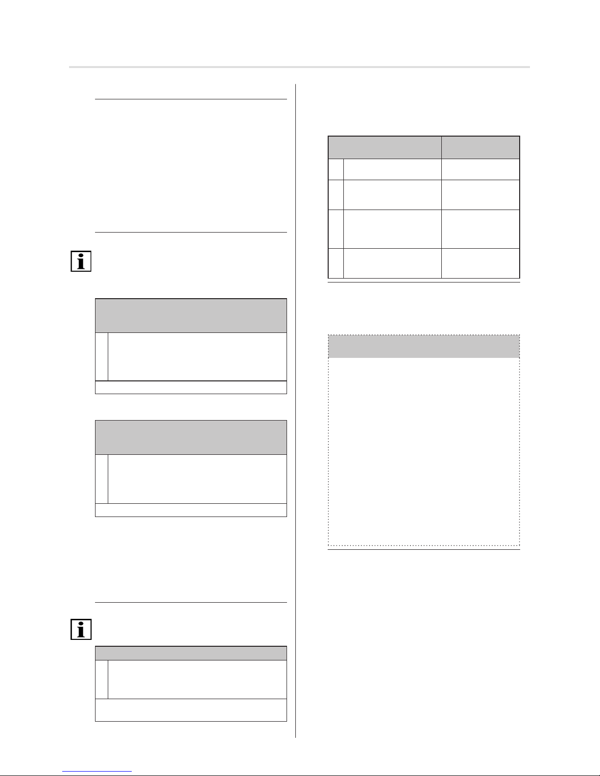
17.6.5Four variants of end position settings
Four dierent combinations of end position settings are
possible. They must be selected sensibly according to the
technical requirements of the Venetian blind.
End position settings
(4 versions)
possible with
AUpper and lower end posi-
tion freely adjustable
T-strap, tapes,
belt
BFixed upper limit stop /
lower end position freely
adjustable
T-strap, tapes,
belt, limit plugs,
angle bracket
CFixed upper and lower limit
stop
Anti push-up device,
sti shaft connector,
limit plugs, angle
bracket
DUpper end position freely
adjustable, xed lower limit
stop
Anti push-up device
Fig. 7 Versions of the end position settings in the RolTop
17.6.6Variant A: Upper and lower end position
freely adjustable
Variant A:
Upper and lower end position freely adjustable
①From a middle Venetian blind position with the as-
sembly cable, push the UP button ▲ until the Vene-
tian blind has reached the desired end position.
The drive starts, stops briey and then moves on
(while the UP button ▲ is pushed).
Correction is possible with the buttons ▲ and ▼ .
②Press the AB button ▼ until the drive stops auto-
matically.
The upper end position has been set.
③Press the AB button ▼ again until the Venetian
blind has reached the desired lower end stop.
The drive starts, stops briey and then moves
on (while the AB button ▼ is pushed).
Correction is possible with the buttons ▲ and ▼ .
④Press the AUF button ▲ until the drive stops
automatically.
The lower end position has been set.
Setting of the end positions variant A is now complete.
Fig. 8 End position setting Variant A:
© elero GmbH EN | 5
Commissioning | Setting the end positions and the relief

17.6.9Variant D: Upper end position freely
adjustable, xed lower limit stop
Variant D: Upper end position freely adjustable,
xed lower limit stop
① From a middle Venetian blind position with the as-
sembly cable, push the UP button ▲ until the Vene-
tian blind has reached the desired end position.
The drive starts, stops briey and then moves on
(while the button is pushed).
Correction is possible with the buttons ▲ and ▼ .
② Press the DOWN button ▼ until the drive stops
automatically.
The upper end position has been set.
③ Press the DOWN button ▼ again until the Venetian
blind has reached the lower end stop (run to lower
end stop).
The drive starts, stops briey and then moves on
(while the DOWN button ▼ is pushed).
The drive switches o automatically when the lower
limit stop is reached.
④ Press the UP button ▲ until the drive stops
automatically.
The lower end position has been set.
Optional: Activation of the relief function for the
lower stop; see chapter 5.6.3
Setting of the end positions variant D is now complete.
Fig. 11 End position setting Variant D:
18 Troubleshooting
Problem /
Error
Possible
cause
Cure
Remedy
• Drive stops
during travel
• End positions
are not set
• Drive is in
setting mode
• Set end posi-
tions
• Drive stops
after a short
time
• End position
programmed
• Sluggish
shutter
• Set second
end position
• Check smooth
running of the
Venetian blind
• Drive runs only
in one direction
• Connection
error
• Check connec-
tion
• Drive not
responding
• No mains
voltage
• Temperature
limiter has
tripped
• Check mains
voltage
• Allow drive to
cool
• Drive does not
learn any end
positions
• Random travel
• Travel to end
position or limit
stop too short
• Delete end
positions
Reset end
positions
• Drive must run,
stop briey
and run on
(while a button
is pushed at
the assembly
cable).
Fig. 12 Error search at the RolTop
6 | EN © elero GmbH
Setting the end positions and the relief | Troubleshooting
17.6.7Variant B: Fixed upper limit stop / lower
end position freely adjustable
Variant B: Fixed upper limit stop / lower end posi-
tion freely adjustable
① From a middle Venetian blind position with the
assembly cable, push the UP button ▲ until the
Venetian blind has reached the desired end position
(run to the upper stop).
The drive starts, stops briey and then moves on
(while the UP button ▲ is pushed).
The drive switches o automatically when the upper
limit stop is reached.
② Press the AB button ▼ until the drive stops auto-
matically.
The upper end position has been set.
Optional: Activation of the relief function for the
upper stop; see chapter 5.6.2
③ Press the AB button ▼ again until the Venetian blind
has reached the desired lower end stop.
The drive starts, stops briey and then moves on
(while the button is pushed).
Correction is possible with the buttons ▲ and ▼ .
④Press the AUF button ▲ until the drive stops auto-
matically.
Setting of the end positions variant B is now complete.
Fig. 9 End position setting Variant B:
17.6.8Variant C: Fixed upper and lower limit stop
Variant C: Fixed upper and lower limit stop
①From a middle Venetian blind position with the
assembly cable, push the UP button ▲ until the
Venetian blind has reached the desired end position
(run to the upper stop).
The drive starts, stops briey and then moves on
(while the UP button ▲ is pushed).
The drive switches o automatically when the upper
limit stop is reached.
② Press the AB button ▼ until the drive stops auto-
matically.
The upper end position has been set.
Optional: Activation of the relief function for the
upper stop; see chapter 5.6.2
③ Press the AB button ▼ again until the Venetian blind
has reached the lower end stop (run to lower end
stop).
The drive starts, stops briey and then moves on
(while the DOWN button ▼ is pushed).
The drive switches o automatically when the lower
limit stop is reached.
④ Press the AUF button ▲ until the drive stops auto-
matically.
The lower end position has been set.
Optional: Activation of the relief function for the
lower stop; see chapter 5.6.3
Setting of the end positions variant C is now complete.
Fig. 10 End position setting Variant C:

19 Repair
The RolTop is maintenance free.
20 Repair
Please contact your dealer if you have any questions.
Please always provide the following information:
• Item number and name on the type plate
• Type of fault
• Previous and unusual events
• Surrounding circumstances
• Own assumption
21 Manufacturer's address
elero GmbH
Antriebstechnik
Maybachstr. 30
73278 Schlerbach
Deutschland / Germany
Phone: +49 7021 9539-0
Fax: +49 7021 9539-212
www.elero.com
Please visit our website if you require a contact outside
Germany.
22 Disassembly and disposal
Dispose of the packaging according to current regulations.
Dispose the product after previous use in accordance with
applicable regulations.
Environmental information
No unnecessary packaging was used. The packaging can
be easily divided into three material types: Cardboard (box),
Styrofoam (padding) and polyethylene (bag, foam material
protective foil).
The device is made up of materials that can be reused if it
is disassembled by a specialist operation. Please observe
the local provisions on disposal of packaging material and
old devices.
Always expect additional danger that does not occur in
operation during disassembly.
WARNING
Danger of injury due to electric current.
Electric shock possible.
►Physically disconnect power supply lines and discharge
charged energy storage. Wait for at least 5 minutes after
deactivation for the motor to cool down and the capaci-
tors to lose their voltage.
►Use suitable, tested and stable climbing aids when per-
forming disassembly work above body height.
►All work at the electrical system must only be performed
by the sta described in the chapter "Safety instructions
for electrical installation".
Scrapping
During the scrapping of the product, the international,
national and regional-specic laws and regulations are to be
complied with.
Please make sure to consider material recyclability, ease of
dismantling, and separability of materials and components
as well as environmental and health hazards during recy-
cling and disposal.
CAUTION
Environmental damage at incorrect disposal
►Electronic scrap and electronic components are subject
to the hazardous waste rules and must only be disposed
of by approved specialist operation.
►Groups of materials such as plastics and metals of vari-
ous kinds are sorted for recycling and disposal process.
Dispose electrical and electronic components
Disposal and recycling of electric and electronic compo-
nents must comply with the applicable national laws and
regulations.
23 Conformity Declaration
elero GmbH hereby declares that this product corresponds
to the applicable directives. The complete declaration of
conformity can be found under www.elero.com.
24 Technical data and dimensions
The indicated technical data are subject to tolerances (ac-
cording to the respective applicable standards).
© elero GmbH EN | 7
Relief function | End position settings

Technical data and dimensions
24.1 RevoLine M
Build / Type RolTop
M6
RolTop
M7/23
RolTop
M10
RolTop
M12/23
RolTop
M20
RolTop
M30
RolTop
M40
RolTop
M50
Rated voltage (V) 1 ~ 230 1 ~ 230 – 240 1 ~ 230
Rated frequency (Hz) 50
Noiseless soft brake • –
High-speed door – • – • –
Rated torque (Nm) 6 7 10 12 20 30 40 50
Rated speed (rpm) 14 23 14 23 14
Rated current (A) 0.52 0.6 0.9 1.2 1.3
Rated power consumption (W) 118 140 200 270 300
Shaft diameter (mm) 50
Protection class (IP) 44
Limit switch range (turns) 40
Operating duration (min S2) 5 4 5 4
Length A (mm) 478 480 530 540 530 540 560
Length B (mm) 460 462 513 523 512 522 542
Weight (kg) 1.5 1.9 2.2 2.3 2.6 3.1
Operating environment temperature
(°C) – 20 to +60
Conformity
Emission sound pressure level
(dBA) < 70
Protection class I •
Plug-in connecting cable (m) 2.0
Item number 34 301.0001 34 225.0001 34 221.0001 34 235.0001 34 231.0001 34 241.0001 34 251.0001 34 261.0001
8 | EN © elero GmbH
33
D
C
E
Stator FE C D E Motorrohr
Rol/Sun/Vari
381 364 elero=14 339
391 374 RH=12 349
456 439 SH=19 414
466 449 424
486 469 444
526 509 484
546 529 504
RolTop M1,8/138 RH Neher 384493401 120 556 539 514
RolTop M1,8/138-868 RH Nehe r 384403406 120
D= C-17mm (halbe Kupplung)
Baugröße Typ
55
C
D
E
E
45O
55O52,7
C
D
33
33
C
D
33
E
45O45O45O
O52,7
C
D
33
45O
O57,5
E
C
D
33
45O
O57,5
E

Build / Type RolTop
M6
RolTop
M7/23
RolTop
M10
RolTop
M12/23
RolTop
M20
RolTop
M30
RolTop
M40
RolTop
M50
Rated voltage (V) 1 ~ 230 1 ~ 230 – 240 1 ~ 230
Rated frequency (Hz) 50
Noiseless soft brake • –
High-speed door – • – • –
Rated torque (Nm) 6 7 10 12 20 30 40 50
Rated speed (rpm) 14 23 14 23 14
Rated current (A) 0.52 0.6 0.9 1.2 1.3
Rated power consumption (W) 118 140 200 270 300
Shaft diameter (mm) 50
Protection class (IP) 44
Limit switch range (turns) 40
Operating duration (min S2) 5 4 5 4
Length A (mm) 478 480 530 540 530 540 560
Length B (mm) 460 462 513 523 512 522 542
Weight (kg) 1.5 1.9 2.2 2.3 2.6 3.1
Operating environment temperature
(°C) – 20 to +60
Conformity
Emission sound pressure level
(dBA) < 70
Protection class I •
Plug-in connecting cable (m) 2.0
Item number 34 301.0001 34 225.0001 34 221.0001 34 235.0001 34 231.0001 34 241.0001 34 251.0001 34 261.0001
24.2 RevoLine S
Technical data and dimensions
© elero GmbH EN | 9
C
E
D
33
CDE
Drehzahl
RolTop/V ari Eco S1,5 70/84 534 517 11
RolTop/V ari Eco S3 30/36 534 517 11
RolTop/V ari Eco S5 (17)/19/20 534 517 11
RolTop S7 30
RolTop/V ari Eco S8 (17)/-/- 534 517 11
RolTop/V ari Eco S12 (17)/19/20 534 517 11
RolTop/V ari Eco S10 514 497 11
Baugröße Typ
Maße mit und ohne Funk
C
E
D
33
35
O
35
O
O
39
O
39
Baugröße / Typ S1,5/70 S3/30 S5/30 S5 S8 S10 FL S12 FL S12/11 FL
Roller shutter ■ ■ ■ ■ ■ ■
Roller blind ■ ■ ■ ■ ■ ■ ■ ■
Noiseless soft brake ■ ■ ■ ■ ■ - - -
Rated voltage [V] 1 ~ 230 1 ~ 230 1 ~ 230 1 ~ 230 1 ~ 230 1 ~ 230 1 ~ 230 1 ~ 230
Rated frequency [Hz] 50 50 50 50 50 50 50 50
Rated torque [Nm] 1,5 3 5 5 8 10 12 12
Rated speed [1/min] 70 30 30 17 17 17 17 11
Rated current [A] 0,55 0,55 0,73 0,55 0,73 0,55 0,73 0,55
Rated power consumption [W] 130 130 168 130 168 130 168 130
Shaft diameter [mm] 38 38 38 38 38 38 38 38
Limit switch range (turns) 160 80 80 40 40 40 40 40
Protection class (IP-Code) 44 44 44 44 44 44 44 44
Operation duration (min S2) 5 5 4 5 4 4 4 4
Length C [mm] 534 534 534 534 534 514 534 514
Length D [mm] 517 517 517 517 517 497 517 497
Length E [mm] 11 11 11 11 11 11 11 11
Weight [kg] 1,3 1,2 1,2 1,2 1,3 1,2 1,4 1,2
Operating environment
temperature [°C] -20 ... 60 -20 ... 60 -20 ... 60 -20 ... 60 -20 ... 60 -20 ... 60 -20 ... 60 -20 ... 60
Protection class I
■ ■ ■ ■ ■ ■ ■ ■
Conformity
■ | ■ | ■ ■ | ■ | ■ ■ | ■ | ■ ■ | ■ | ■ ■ | ■ | ■ ■ | ■ | ■ ■ | ■ | ■ ■ | ■ | ■
Artikel-Nr. (Rundkopf /
Sternkopf) 302210001 302110001 302310001
302330001
302530001
308230001
308130001
30815001

We reserve the right to make technical changes
elero GmbH
Antriebstechnik
Maybachstr. 30
73278 Schlierbach
www.elero.com
Phone: +49 7021 9539-0
Fax: +49 7021 9539-212
Technical data and dimensions
24.3 RevoLine M RH
Build / Type RolTop
M4/60 RH
RolTop
M7/23 RH
RolTop
M10 RH
RolTop
M12/23 RH
RolTop
M20 RH
RolTop
M30 RH
Rated voltage (V) 1 ~ 230
Rated frequency (Hz) 50
Noiseless soft brake –
High-speed door • – • –
Rated torque (Nm) 4 7 10 12 20 30
Rated speed (rpm) 60 23 14 23 14
Rated current (A) 0.9 0.6 0.9
Rated power consumption (W) 200 140 200
Shaft diameter (mm) 50
Protection class (IP) 44
Limit switch range (turns) 40
Operating duration (min S2) 4 5 4
Length A (mm) 540 480 530 540 530
Length B (mm) 523 462 513 523 512
Weight (kg) 2.2 1.9 2.2 2.3
Operating environment temperature
(°C) – 20 to +60
Conformity
Emission sound pressure level
(dBA) < 70
Protection class I •
Plug-in connecting cable (m) 2.0
Item number 38 469.0001 38 225.0001 38 221.0001 38 235.0001 38 231.0001 38 241.0001
Build / Type RolTop
L60
RolTop
L80
Rated voltage (V) 1 ~ 230
Rated frequency (Hz) 50
Noiseless soft brake –
Application protection up and down
and reversion on obstacle •
Rated torque (Nm) 60 80
Rated speed (1/min) 14
Rated current (A) 1,9 2,0
Rated power consumption (W) 430 470
Shaft diameter (mm) 63
Protection class (IP) 44
Limit switch range (turns) 40
Operating duration (min S2) 4
Length A (mm) 589,4
Length B (mm) 572,4
Weight (kg) 3,3 3,6
Operating environment temperature
(°C) – 20 bis +60
Conformity
Emission sound pressure level
(dBA) < 70
Protection class I •
Plug-in connecting cable (m) 2,0
Item number 36 731.0001 36 741.0001
24.4 RevoLine L
This manual suits for next models
22
Table of contents
Other elero Indoor Furnishing manuals


Popular Indoor Furnishing manuals by other brands

Regency
Regency LWMS3015 Assembly instructions

Furniture of America
Furniture of America CM7751C Assembly instructions

Safavieh Furniture
Safavieh Furniture Estella CNS5731 manual

PLACES OF STYLE
PLACES OF STYLE Ovalfuss Assembly instruction

Trasman
Trasman 1138 Bo1 Assembly manual

Costway
Costway JV10856 manual


