elero VariEco M NHK Series User manual
RevoLine VariEco NHK
Assembly instructions
138164001_EN_0519
General
Application: Tubular drive for small rolling doors, roller shut-
ters and textile sun protection
Limit stop: Mechanical
Special feature: Emergency manual operation, noiseless
soft brake (up to 20 Nm)
Shaft size: Type M from Ø 50 mm, type L from Ø 63 mm
Standard scope of delivery
•2 m connecting cable, assembly instructions
Accessories
•Adapter sets, motor bearing, control units
Safety instructions
General safety instructions for use including installation of
drives for roller shutters, awnings and textile sun protection
can be found in the “Safety instructions” leaet supplied with
each drive. Please read the general safety instructions and
this installation manual carefully as the procedure in this
manual is a prerequisite for correct use of the product. Any
intervention by unqualied personnel or failure to comply with
warnings may lead to personal injuries or material damage.
Figures included are for illustration purposes only. The illus-
trations may dier from your product with respect to minor
details and are provided for general information only.
elero GmbH continuously strives to improve all products. As a
result, the specications, features and technology of this prod-
uct may be changed at any time. The information provided is
based on current information at the time of publication.
No claims can be derived from the technical data, images and
information provided in this manual.
&$87,21
Assembly
•Only connect the drive with the power turned o.
•Only insert the drive's plug with the power turned o.
•The drive is only capable of operation while installed.
•Never adjust the end position to a mechanical stop.
•The length of the winding shaft is determined for each
specic installation depending on the drive head and motor
bearing used at the installation site.
•Do not drill holes in the area of the tubular drive.
Installation in prole tubes
•Push drive with the suitable drive adapter and limit switch
crown into the prole tube. Install the shaft with drive and
counterpart support so that the limit switch setting mechanism
is accessible.
•Secure the counterpart support to prevent axial movement
(screw on the idler or rivet it on).
•Connect the drive to the elero assembly cable, matching up
the core colours.
•Allow the drive to run in DOWN/CLOSED direction until the
limit switch cuts out.
•Attach the blind to the shaft.
Installation in round tubes
•On the round tube, cut a slot in the end of the tube on the
drive side.
•Push the drive in so that the lug of the drive engages in the
slot.
•Screw in the drive adapter or rivet it.
•Allow the drive to run in DOWN/CLOSED direction until the
limit switch cuts out.
•Attach the blind to the shaft.
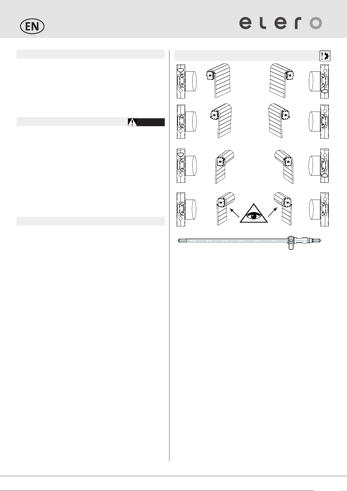
Adjustment of end positions
Adjusting key: item number 13 109.6401
NOTE: For activation of the limit switch setting screws, use the
setting tool or Phillips/hexagon socket tool. Never use an electric
screwdriver!
Important: The limit switch setting screws for the upper end posi-
tion and lower end position are assigned depending on the paral-
lelism of the rotating limit switch crown with the running direction
arrow.
Upper end position
1. Allow the drive (without blind) to run fully in DOWN/CLOSED
direction.
2. Attach the rolled-down blind to the shaft.
3. Push the [OPEN ▲] button and keep this held down.
4. Using the setting tool, turn the limit switch setting screw in posi-
tive or negative direction until you reach your desired upper
end position.
Lower end position
5. Push the [DOWN/CLOSED ▼] button and keep this held down.
6. Using the adjusting key, turn the DOWN limit switch setting
screw in positive or negative direction until you reach your
desired lower end position.
Checking the end positions
Allow the drive to run into the relevant end position until the limit
switch cuts out. The electric cut-out must take place before the
blind has reached the end position of its mechanical travel path.
If the blind is constantly operated as far as its end position, there
is a risk of damage to the drive and/or blind or even a danger it
will be destroyed.
Take into account any possible changes to the length of the blind
due to temperature uctuations or weather inuences. Allow for a
safety margin.
UP
DOWN/
CLOSE
DOWN/
CLOSE
UP
DOWN/
CLOSE
UP
UP
DOWN/
CLOSE
UP
DOWN/
CLOSE
DOWN/
CLOSE
UP
DOWN/
CLOSE
UP
UP
DOWN/
CLOSE

Technical data and dimensions
The technical data specified is subject to tolerance factors
(according to applicable standards).
All illustrations are non-binding.
EU Conformity
elero hereby declares that this product is in compliance with the
essential requirements and other relevant provisions of Europe-
an directives 2006/42/EG that are applicable in Europe. A decla-
ration of conformity is available at the website
www.elero.com/downloads-service/
Notes on troubleshooting
Fault
Cause
Remedy
•The drive does
not switch o in
the end position
via the limit
switches
•Drive does not
react
•Limit switch
crown is not
being driven
•Readjust instal-
lation and limit
switches via the
limit switch ad-
justment screws
•Set limit switch
•Drive does not
react
•Incorrect
connection
•Readjust
connection
Manufacturer's
address
Service
elero GmbH
73278 Schlierbach
GERMANY
www.elero.de
If malfunctions have occurred or the
device has been damaged despite
proper handling, please contact your
contractor or dealer.
RevoLine VariEco NHK
Assembly instructions
Electrical connection
Note:
Due to feedback voltage from the installed capacitor, never
connect several drives in parallel.
The motor controls in UP/DOWN direction must be inter-
locked with one another. A reversing delay of at least 0.5 sec.
must be ensured.
102
reseau electrique
L
N
PE
230V/50Hz
vert-jaune
brun
noir
bleu
de volet
M
1~
102
rete
L
N
PE
230V/50Hz
verde/giallo
marrone
nero
blu
M
1~
102
Netz
L
N
PE
230V/50Hz
grün/gelb
braun
schwarz
blau
oder -taster
M
1~
102
power grid
L
N
PE
230V/50Hz
green/Yellow
brown
black
blue
junction box
M
1~
boiter de scatola di
derivatione
26E=
D
C
33
F
Stator FE C D E Motorrohr
M10-17 N HK 120V 621 604 26 565
M20 NHK/ M16-17 NHK 120V 661 644 26 605
M30 NHK/ M36-12 NHK 120V 651 634 26 595
M50 NHK 681 664 26 625
Rol TopD+ M6 NHK 524 507 26 468
Rol TopD+ M10 NHK 544 527 26 488
Rol TopD+ M20 NHK 604 587 26 548
Rol TopD+ M30 NHK 594 577 26 538
Baugröße Typ
100
74
91,5
O
60
90
30°
M6
16
q
2 | EN
Emergency crank handle
Note:
Tubular drive versions with the additional code NHK are tted
with an emergency unlocking device.
The emergency unlocking device ensures that the blind can be
opened or closed in case of an emergency. Examples of emer-
gencies might be blackouts or a defect to the tubular drive.
The emergency unlocking device is not intended to be used
on regular basis as otherwise the tubular drive may become
damaged.
Emergency release of the tubular drive via the manual
override/emergency crank handle
CAUTION
•Hands, loose items of clothing or long hair may become
entrapped and crushed.
•Disconnect the tubular drive from the mains power prior to
emergency unlocking (switch should not be operated).
•Attach the manual override/emergency crank handle to the
tubular drive.
•Open or close the blind slowly by turning the manual override/
emergency crank handle.
•Ensure that you do not go past the limit switches set.
wall anchors
13 106.3501
wall anchors
13 301.0801
7 mm 6-edge
with awning loop
23 771.0002
front element
Spherical bearing for coupling funnel 23 772.0002
articulated crank with spherical bearing and
7 mm hexagonal 23 764.0002
Spherical bearing with awning eyelet 23 731.0002
ø 12.5 x 18.5 tief
for front elements
with ø 12 bolts
Connecting
cable pluggable
334488443300000011
348430001.asm
31.07.2014 fleischerd
-
VVaarriiEEccooMM3300NNHHKK
1:2
-
Diese Maße werden besonders geprüft
This dimensions are particularly examined
Kanten gebrochen
Edges broken
Allgemeintoleranzen
General Tolerances:
DIN ISO 2768-1 m-E
DIN ISO 2768-2 K-E
Maßstab / Scale:
Werkstoff / Material:
Datum / Date: Name:
A-EW
geprüft
proofed:
Benennung / Title:
Zeichnungsnummer / Drawingnumber:
Werkzeug-Nr
Tool-Number:
GGeemmääßßRRooHHSS--RRiicchhttlliinniiee22001111//6655EEGG//aaccccoorrddiinnggttooRRooHHSSddiirreeccttiivvee220000//1111//EEUU
Index: Kurzbeschreibung / Short Comment: Name:
Datum / Date:
elero GmbH
Antriebstechnik
Linsenhofer Str. 65, D-72660 Beuren
Fon: (0049) 7025 / 13-01
Fax: (0049) 7025 / 13-390
Verwendung , Kennzeichnung / Used in, Spezification:
Gewicht / weight: 2510 g
Solid Edge
a
b
c
d
-
-
-
-
-
Rohrindex erhöht, Schraube war 101010907.
Typenschild geä.
MiniPlug entfernt
Drehmomentangaben hinzu gekommen.
-
-
-
-
-
20.06.2017
24.10.17
06.12.17
30.10.2018
-
-
-
-
-
FLD
HEC/WAT
HEC/WAT
FLD
-
-
-
-
-
-
Blatt / Sheet: Blattanzahl / Number of sheets: -
CAD-Nr / CAD-No:
231290001
1233941201
1231620002
1
138066003
1
133092102
1
Menge Mengeneinheit Dokumentnummer Titel Material Kommentar
1 STK 233941201 Motor M H90 Fl
1 STK 231620002 Endschalter kpl. 6F
1 STK 231290001 Getriebe
1 STK 138200001 Sicherheitshinweis -
1 STK 138164001 Einstellanleitung
1 STK 138066003 Aufkleber Typenschild -
1MM 138037103 Transferfolie 110x450 lfm.TMX Super Pr.
CAB
1 STK 133092102 Motorrohr 595 Präz. St-Rohr 45 x 1,5 DIN 2393
4 STK 101014701 Senkschraube EJOT Altracs Plus 4x10
Torx 20
St verzinkt
2 STK 101013621 Schraube WN 1552 - DG35x7 St verzinkt EJOT Nr.:441 0383
801
101014701
4
101013621
2
677
629
91,5
74
100
90
45
O
Lauffläche muß mit PD1 gefettet werden./
Bearing surface has to be lubricated whith PD1.
26
63
+7
-3
60
LK
Schrauben mit 4,3
u
0,3 Nm anziehen./
Tighten the screws whith 4,3
u
0,3 Nm.
a
a
Link für Typenschildabstand
b
Excelstückliste
Drehmoment nach Arbeitsanweisung./
Torque according to work instruction.
Drehmoment nach Arbeitsanweisung./
Torque according to work instruction.
d
d
d
Rear cable
outlet

Size / Type VariEco
M20 NHK
VariEco
M30 NHK
VariEco
M40 NHK
VariEco
M50 NHK
VariEco
L40 NHK
VariEco
L60 NHK
VariEco
L80 NHK
VariEco
L100 NHK
VariEco
L120 NHK
Rated voltage [V] 1 ~ 230 1 ~ 230 1 ~ 230 1 ~ 230 1 ~ 230 1 ~ 230 1 ~ 230 1 ~ 230 1 ~ 230
Noiseless soft brake • - - - - - - - -
Rated torque [Nm] 20 30 40 50 40 60 80 100 120
Rated speed (1/min) 14 14 14 14 14 14 14 11 11
Rated current [A] 0,90 0,90 1,05 1,30 1,45 1,55 1,80 1,70 2,00
Rated power
consumption [W]
200 200 242 300 333 356 415 390 460
Shaft diameter 50 50 50 50 63 63 63 63 63
Protection class (IP) 44 44 44 44 44 44 44 44 44
Limit switch range
(revolutions)
29 29 29 29 29 29 29 29 29
Operating time
(min S2)
4 4 5 4 4 4 4 4 4
Length C [mm] 661 651 682 682 730 730 760 760 760
Length D [mm] 644 634 665 665 713 713 743 743 743
Length E [mm] 27 27 27 27 27 27 27 27 27
Ø F [mm] 45 45 45 45 58 58 58 58 58
Weight [kg] 2,2 2,5 2,7 3,1 5,76 576 6,2 6,2 6,2
Ambient operating
temperature [
°C
]
-20 to 60 -20 to 60 -20 to 60 -20 to 60 -20 to 60 -20 to 60 -20 to 60 -20 to 60 -20 to 60
Protection class I • • • • • • • • •
Plug-in connection
cable [m]
2.0 2.0 2.0 2.0 2.0 2.0 2.0 2,0 2,0
Item number 34 833.0001 34 843.0001 34 853.0001 34 863.0001 36 925.0002 36 935.0002 36 945.0001 36 955.0001 36 965.0001
RevoLine VariEco NHK
Assembly instructions
Technical data and dimensions:
VariEco M NHK / VariEco L NHK
EN | 3
elero GmbH
Antriebstechnik
Maybachstr. 30
73278 Schlierbach
www.elero.com
Subject to technical changes
This manual suits for next models
10
Other elero Indoor Furnishing manuals


Popular Indoor Furnishing manuals by other brands


Next
Next DARCY 126284 Assembly instructions

Naterial
Naterial LYRA II 2022R09P01-0103 Assemby - Use - Maintenance Manual

Rapidline
Rapidline AM100 Assembly instructions

Touchstone
Touchstone Whisper Lift II PRO owner's manual

WIEMANN
WIEMANN WIEMANN 991404 manual

Contender
Contender C990476-101 Assembly instructions