elero VariEco S3/30-K User manual

VariEco S-K
Drive for roller shutters
and textile sun protection
138195501_EN_0116
VariEco S-K
Drive for roller shutters
and textile sun protection
1 Operating and installation instructions
Please keep these operating instructions for later use, to be
available throughout the life of the product!
The German manual is the original version.
All other documents represent the language translations of
the original text.
All rights in the case of a patent, utility model or ornamental
design registration are reserved.
2 General for instructions
The content structure is based on the life cycles of the elec-
tric motor drive (hereinafter referred to as "Product").
The manufacturer reserves the right to make changes to
the Specications stated in these Operating Instructions
at any time. These may, in individual cases, be different
from the respective product version, however the functional
information will not undergo signicant changes or become
invalid. The current version of the Specications may be
requested from the manufacturer at any time. No claims
may be asserted against the manufacturer as a result of the
preceding sentence. Deviations from text or picture state-
ments are possible and depend on the technical develop-
ment, features, and accessories of the products. Deviating
information on special versions will be explained by the
manufacturer in the sales documentation. Other information
shall remain unaffected by these provisions.
2.1 Standards and Directives
During the design process, the basic health and safety
requirements of the applicable laws, Standards and Direc-
tives were complied with. The safety is conrmed by the
declaration of conformity (see "Declaration of Conformity").
All safety information in these Operating Instructions refer
to the laws and regulations currently applicable in Germany.
All instructions in the Operating Instructions shall be ob-
served without limitation and at any time. Beside the safety
instructions contained in these Operating Instructions, the
provisions for accident prevention, environmental protection
and occupational safety, which are applicable for the op-
erating site, must be observed. Provisions and Standards
for the safety rating can be found in the EC Declaration of
Conformity
2.2 Intended use
The product is intended for electrically powering roller shut-
ters and textile sun protection.
The determining factor for the drive is the elero
drive computation program (http://elero.de/
antriebsberechnungsprogramm).
Further elds of application have to be arranged with the
manufacturer, elero GmbH Antriebstechnik (see Address).
The operator will be solely responsible for damages result-
ing from improper use of the product. The manufacturer
cannot be held liable for personal or material damages
caused by misuse or procedural errors, and by improper
operation and commissioning.
The product may be operated only by authorized or trained
personnel under observance of all safety.
Table Of Contents
1 Operating and installation instructions 1
2 General for instructions 1
2.1 Standards and Directives 1
2.2 Intended use 1
2.3 Foreseeable misuse 2
2.4 Warranty and liability 2
2.5 Customer service of the manufacturer 2
3 Safety 2
3.1 General safety instructions 2
3.2 Layout of the safety guidelines 2
4 Product description 3
5 Assembly 3
5.1 Mechanical fastening 3
5.2 Electrical connection 4
5.3 Connection example VariEco 230 V / 50 Hz 4
5.4 Commissioning 5
5.5 Setting the end positions 5
5.6 Checking the end positions 5
6 Troubleshooting 5
7 Maintenance 5
8 Repair 6
9 Manufacturer's address 6
10 Disassembly and disposal 6
11 Notes on the EU declaration of conformity 6
12 Technical data and dimensions 7
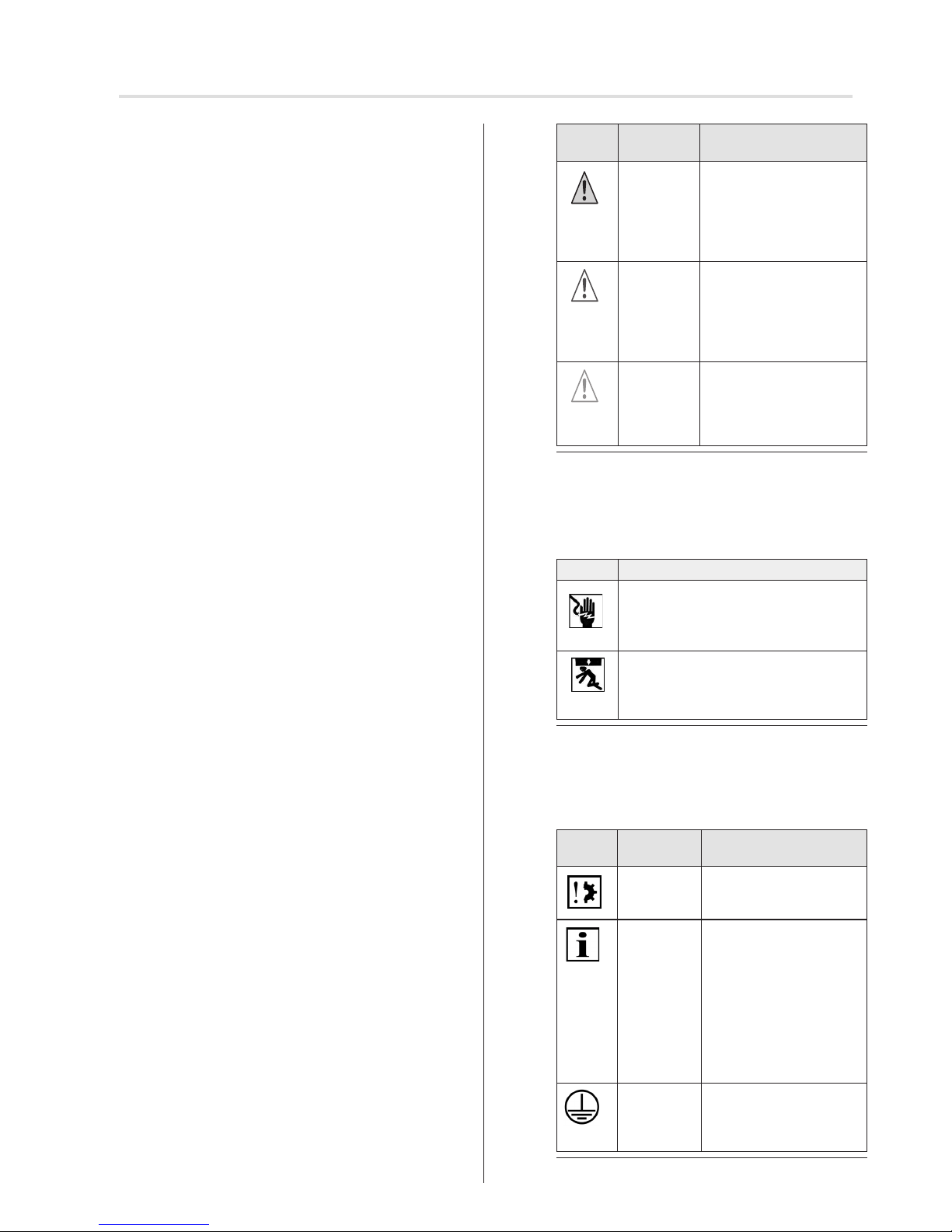
Symbol Signal
word
Meaning
DANGER Warns before an acci-
dent, which will result if
instructions are not fol-
lowed, which can lead to
life-threatening, irreversi-
ble injury or death.
WARNING Warns before an acci-
dent, which can happen
if the instructions are not
followed, which can lead
to serious, possibly fatal,
irreversible injury or death.
CAUTION Warns before an accident,
which can happen if the
instructions are not fol-
lowed, which may lead to
minor reversible injury.
Fig. 1 Notation of personal injury
The following table describes the icons used in these op-
erating instructions that are used for imaging of the dan-
gerous situation in connection with the symbol of the threat
level.
Symbol
Meaning
Danger of electric voltage, electric
shock:
This symbol indicates a risk of electric
shock.
Danger of crushing and striking dead of
persons: This symbol indicates dangers
where the entire body or individual body
parts can be crushed or injured.
Fig. 2 Notation-specic hazard
The following table denes the representation used in the
operating instructions and description of situations where
damage can occur to the product or refers to important
facts, conditions, tips and information.
Symbol Signal
word
Meaning
NOTE This symbol warns of a
possible property dam-
age.
Important: This symbol points out
important facts and con-
ditions as well as to addi-
tional information in these
operating and installation
instructions. It also refers
to certain statements that
give additional information
or help you perform a task
easily.
Symbol for earthing in
protection class I
(protective ground sys-
tem)
Fig. 3 Notation of property damage as well as additional
information
2 | EN © elero GmbH
Intended Use | Security
Only if used according to the specications of these operat-
ing and installation instructions for the safe and proper use
and safe operation of the product are guaranteed.
Intended use includes the observance and compliance with
all safety instructions with regards to this operating manual
and all applicable regulations, and professional associations
of applicable laws for environmental protection. Intended
use includes the observance of prescribed operating rules
in these operating and installation instructions.
2.3 Foreseeable misuse
A use which deviates from the intended use stated by the
manufacturer, elero GmbH Antriebstechnik (see "Address"),
is deemed as foreseeable misuse.
2.4 Warranty and liability
Principally, the General Terms and Conditions of the man-
ufacturer, elero GmbH Antriebstechnik (see "Address"),
apply. The terms and conditions are part of the sales
documents and handed over to the operator upon deliv-
ery. Liability claims for personal or material damages are
excluded when they can be attributed to one or more of the
following causes:
• Opening of the product by the customer
• Unintended use of the product
• Improper installation, commissioning, or operation of the
product
• Structural modications to the product without the written
consent of the manufacturer
• Operation of the product with improperly installed con-
nections, defective safety devices or improperly installed
safeguards
• Non-observance of the safety provisions and instructions
of these Operating Instructions
• Non-compliance with the technical data
2.5 Customer service of the manufacturer
The product should only be repaired by the manufacturer
in case of a failure. The address for sending to customer
service, see the chapter "Address".
If you have not purchased the product directly from elero,
please contact the supplier of the product.
3 Safety
3.1 General safety instructions
The general safety notes when using pipe drives can be
found in the leaet "Instructions on safety" that is enclosed
with each drive"(leaet item no. 138200001). These operat-
ing and installation instructions contain all the safety instruc-
tions that must be observed in order prevent and eliminate
hazards in the handling of the product in the individual life
cycles. The safe operation of the product can only be en-
sured when all given safety instructions are observed.
3.2 Layout of the safety guidelines
The safety instructions in this document are identied by
hazard signs and safety symbols and are designed accord-
ing to the SAFE principle. They contain information on the
nature and source of the danger of possible consequences
and to prevent the danger.
The following table denes the representation and descrip-
tion of hazard levels with possible personal injury, as used
in this manual.

The following example represents the basic structure of a
safety warning:
SIGNAL WORD
Type and source of danger
Explanation of the type and source of the danger
►Measures to prevent the danger.
4 Product description
The VariEco S-K is an electromechanical tubular motor
drive. It performs parallel axial movements.
Commissioning of the VariEco S-K with elero installation
cable for comfortable setting.
5 Assembly
Observe the usual obligation to exercise care with technical
products to minimise other risks.
WARNING
Danger of injury from incorrect assembly
Important safety instructions.
►Observe all assembly instructions, since incorrect assem-
bly may cause severe injury.
CAUTION
Personal injury from hot surfaces.
Drive heats up during operation, the drive housing can be
hot. Possible burning of the skin.
►Wear personal protective equipment (gloves).
►Activation duration and standby times of the drives must
be observed.
Triggered by a possible material errors may occur or
impact shock and injury due to a gearbox break, bud break
or a clutch defect.
►Suitable materials are to be used for the construction as
well as perform a sampling inspection by double load test
according to DIN EN 60335-2-97.
Risk of injury due to impact or shock caused by not prop-
erly mounted or latched motor bearings. Hazards caused
by insufficient stability or stability and stored energy (grav-
ity).
►Selection of engine bearing torque specications.
►Drive must be backed up with all attached backup devic-
es.
►Check for proper latching on engine mounts and correct
tightening torques.
WARNING
Danger of injury due to electric current.
Electric shock possible.
►Electrical work can only be performed by an authorized
electrician.
Danger of injury due to electric current.
Hazardous possibly by parts that have become live in the
error state.
►Electrical connection is described in the operating and
installation instructions included cable bushing.
CAUTION
Risk of injury due to malfunctions due to improper installa-
tion.
Drive over-winds and possibly destroys parts of application.
►For safe operation, the end positions must be set / pro-
grammed.
►Training program of the manufacturer for specialist com-
panies.
NOTE
Loss of power supply, termination of machine parts and
other malfunctions.
►For safe operation, no false mount must be made and the
end position settings must be carried out during commis-
sioning.
Damage to the VariEco S-K due to moisture penetration.
►For devices with protection class IP44, the ends of all
cables or connectors must be protected against the
ingress of moisture. This measure must be implemented
immediately after removal of the VariEco from the original
packaging.
►The drive must be installed in a position in which it is not
sprinkled.
Damage to the application from incorrect assembly.
►Observe the notes in the documents of the manufacturers
of applications and the accessories used.
Important
For best interaction of drive and application, the end posi-
tions must be set at the drive after installation of the
VariEco S-K.
5.1 Mechanical fastening
Important preliminary consideration:
The working space around the built-in drive is usually very
small. Therefore, before the mechanical installation provide
an overview of the implementation of the electrical connec-
tion (see Section 5.2) and make any necessary changes
right away.
NOTE
Damage to the electrical wiring by squeezing or tensile
loading.
►Route all electrical cables so that they are not subjected
to crushing or tensile load.
►Note the bending radius of the connection lines (at least
50 mm).
►Lay the connection line in a loop downwards to prevent
water running into the drive.
Damage to the drive by the action of impact forces.
►Insert the drive into the shaft, never thrust the drive into
the shaft or smash onto the drive!
►Never allow the drive to fall!
Damage or destruction of the drive by drilling.
►Never drill into the drive!
Damage or destruction of the drive by setting the end posi-
tion to the mechanical stop.
►It is not permitted to adjust the end position to a mechan-
ical stop.
© elero GmbH EN | 3
Product description | Assembly

►The motor control must be interlocked in UP/DOWN
direction. A reversing delay of 0.5 seconds must be
ensured.
►Parallel switching of several VariEco S-K drives is only
possible with separating relay.
Damage to the application from incorrect running direction
►The assignment of the running direction UP/DOWN must
be reviewed after the electrical connection has been
established.
Adjustment of the end position at the drive.
►Any adjustment of the end positions that occurs indicates
an electrical connection error. Readjustment of the end
positions is not sufcient in this case, since the end
positions are adjusted often. In this case, the drive needs
to be replaced and the cause removed.
Important
Permanently installed control devices shall be clearly dis-
played.
Important
If the VariEco S-K is used in locations that are not "dry
rooms" (e.g. in the outdoor area, in wet rooms or if it is
excluded that the roller shutter boxes are reliably protected
from moisture by their construction or by roof protrusions
and similar things), the drive must be installed with connec-
tion lines suitable for the installation situation or the con-
nection lines must be protected by conduits. This also
applies to protection from direct solar irradiation.
All applicable standards and provisions must be observed
for the electrical installation.
When connecting the drive to a control, the operating
instructions of the control must be observed.
►Only perform connecting work with the power turned off.
5.3 Connection example VariEco 230 V / 50 Hz
Fig. 4 Circuit diagram VariEco S-K mit 230 V / 50 Hz
5.4 Commissioning
WARNING
Danger of injury from powered parts moving faster than
150 mm/s (application) at VariEco S1,5/70 speed 70
(1/min).
Crushing and striking dead of persons possible.
Standard DIN EN 60335-2-103, part 20.108, is the basis for
impact on an obstacle. It is recommended to limit the
forces by using a catching protection system with sensors
or by switches with off-presettings.
① ② ③ ④
230 V / 50 Hz AC
Junction box
(outside of roller shut-
ter case)
Switch box
1black
2brown
3blue
4green/yellow
4 | EN © elero GmbH
Assembly
Installation in prole tubes / installation in round
tubes
1 Insert drive with matching adapter and limit switch
tappet ring in the prole pipe.
1a Only when installing in the round tube:
On round tubes, cut a slot in the end of the tubes
on the drive side (width 4 mm, length 16 mm)!
1b Push the drive into the round tube and place it so
that the tappet wedge (the inner groove) ts into
the intended cut-out.
2Secure the counterpart support to prevent axial
movement, e.g. screw or rivet on the idler.
3Screw in the coupling (adapter) or rivet it (for round
tube only). Secure the drive in the motor-bearing
against axial movement,
4Attach the roller shutter to the shaft. If the applica-
tion can only be attached to a twisted winding shaft,
switch on the drive in direction downwards until the
drive switches off at the bottom end point (lower
end of the running path reached).
The drive is connected to the prole tube/round tube.
Installation in prole tube/round tube
B
A
C
1
4
2
3
The drive is connected to the prole tube/round tube.
5.2 Electrical connection
WARNING
Danger to life due to faulty electrical connection.
Electric shock possible.
►Before commissioning check the correct connection of
the PE conductor.
NOTES
Damage to the VariEco S-K by faulty electrical connection.
►Before commissioning check the correct connection of
the PE conductor.
Damage or destruction of VariEco S-K by the penetration of
moisture.
►For units with protection class IP 44, the customer con-
nection of the cable ends or connector (cable bushing)
must also be carried out in accordance with protection
class IP 44.
Damage or destruction of VariEco S-K for variants with 230
V AC 1 due to faulty control.
►Switch with OFF setting (Dead man) for drives must be
installed within sight of the VariEco S-K, but away from
any moving parts and amounting to about 1.5 m.
►The motor control must be interlocked in UP/DOWN
direction. A reversing delay of 0.5 seconds must be
ensured.
►Parallel switching of several VariEco S-K drives is only
possible with separating relay.
Damage to the application from incorrect running direction
►The assignment of the running direction UP/DOWN must
be reviewed after the electrical connection has been
established.
Adjustment of the end position at the drive.
►Any adjustment of the end positions that occurs indicates
an electrical connection error. Readjustment of the end
positions is not sufcient in this case, since the end
positions are adjusted often. In this case, the drive needs
to be replaced and the cause removed.
Important
Permanently installed control devices shall be clearly dis-
played.
Important
If the VariEco S-K is used in locations that are not "dry
rooms" (e.g. in the outdoor area, in wet rooms or if it is
excluded that the roller shutter boxes are reliably protected
from moisture by their construction or by roof protrusions
and similar things), the drive must be installed with connec-
tion lines suitable for the installation situation or the con-
nection lines must be protected by conduits. This also
applies to protection from direct solar irradiation.
All applicable standards and provisions must be observed
for the electrical installation.
When connecting the drive to a control, the operating
instructions of the control must be observed.
►Only perform connecting work with the power turned off.
5.3 Connection example VariEco 230 V / 50 Hz
Fig. 4 Circuit diagram VariEco S-K mit 230 V / 50 Hz
5.4 Commissioning
WARNING
Danger of injury from powered parts moving faster than
150 mm/s (application) at VariEco S1,5/70 speed 70
(1/min).
Crushing and striking dead of persons possible.
Standard DIN EN 60335-2-103, part 20.108, is the basis for
impact on an obstacle. It is recommended to limit the
forces by using a catching protection system with sensors
or by switches with off-presettings.
① ② ③ ④
230 V / 50 Hz AC
Junction box
(outside of roller shut-
ter case)
Switch box
1black
2brown
3blue
4green/yellow
►The speed of the driven part must be determined by the
operator depending on the diameter of the winding shaft .
►Always observed the product and safety documentation
of the application supplier.
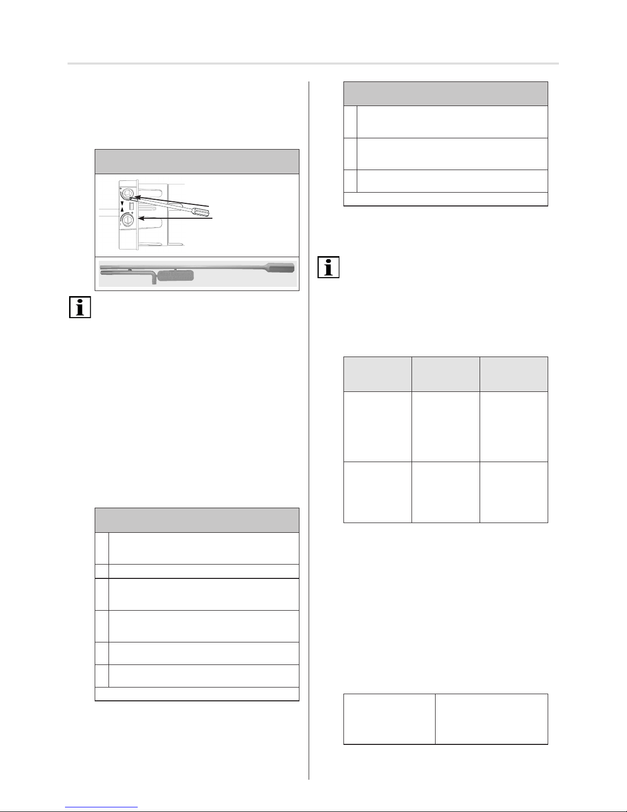
5.5 Setting the end positions
Limit switch: Setting screws
Actuate with setting aid (131163801)
To actuate the limit switch setting screws, use the setting
aid or a Phillips-tip or hexagon socket tool, but never a
power screwdriver.
►6 turns of one of the two limit switch settings crews "UP"
and "DOWN" cause 1 turn of the winding shaft (motor
shaft).
►The maximum limit switch range between the upper and
lower end positions is 32 turns of the motor shaft.
►The assignment of the upper or lower limit switch setting
screw to the upper or lower end position results from the
respective installation situation (right-hand or left-hand
installation) with the corresponding assignment of the
electrical connections for the running direction.
►Turn one limit switch setting screw
from - (minus) to + (plus) to increase the running path
of the application.
►Turn one limit switch setting screw
from + (plus) to - (minus) to reduce the running path
of the application.
Setting the upper end position
(general setting and ne adjustment)
1 Switch on the drive in direction downwards until the
drive switches off at the bottom end point (lower end
of the running path reached)..
2Attach the application to the winding shaft.
3Let the drive run up by pushing the UP button until
it switches off at the upper end point (for small win-
dows, stop rst by pushing the switch if necessary.
4Turn the limit switch setting screw "Top" in the +
(plus) direction or - (minus) direction until you have
reached the nal end position.
5Adjust the upper end position setting with enough
play.
6 Perform a test run and repeat ne adjustment if
necessary.
The upper end position has been set.
2 limit switch setting
screws with running
direction arrows
Adjusting tool
Setting the lower end position
(general setting and ne adjustment)
1 Switch on the drive in direction downwards until the
drive switches off at the bottom end point (lower end
of the running path reached)..
2Turn the limit switch setting screw "Bottom" in the +
(plus) direction or - (minus) direction until you have
reached the nal end position.
3Perform a test run and repeat ne adjustment if
necessary.
The lower end position has been set.
5.6 Checking the end positions
Allow the drive to run alternately in both directions until the
limit switch switches off.
The electrical deactivation at the top and bottom must be
reached before the end position of the mechanical running
path of the application has been reached.
Persistent running "against block" comes with the danger of
damage or destruction of the drive and/or application.
A change to a top or bottom end position is possible at any
time with the limit switch setting screws.
6 Troubleshooting
Problem /
Error
Possible
cause
Cure
Remedy
• The drive does
not switch off
via the limit
switch
• Drive not
responding
• Limit switch
ring is not
being driven
• Limit switch is
not adjusted
• Lock limit
switch ring
• Drive not
responding
• Wrong connec-
tion
• The thermostat
has triggered
• Readjust con-
nection
• Allow drive
to cool down
(minimum 15
minutes)
7 Maintenance
The VariEco S-K is maintenance-free.
8 Repair
If you have any questions, please refer to your specialised
company. Please always state the following information:
• Item number and item designation on the nameplate
• Error type
• Previous and unusual events
• Surrounding circumstances
• Own assumption
9 Manufacturer's address
elero GmbH
Antriebstechnik
Linsenhofer Str. 65
72660 Beuren
Deutschland / Germany
Phone: +49 7025 13-01
Fax: +49 7025 13-212
www.elero.com
Please visit our website if you require a contact outside
Germany.
© elero GmbH EN | 5
Mounting | Commissioning | End position setting | Repair
This manual suits for next models
2
Table of contents
Other elero Indoor Furnishing manuals


Popular Indoor Furnishing manuals by other brands

Regency
Regency LWMS3015 Assembly instructions

Furniture of America
Furniture of America CM7751C Assembly instructions

Safavieh Furniture
Safavieh Furniture Estella CNS5731 manual

PLACES OF STYLE
PLACES OF STYLE Ovalfuss Assembly instruction

Trasman
Trasman 1138 Bo1 Assembly manual

Costway
Costway JV10856 manual


