Elesa DD51-E User manual

Direct drive electronic position indicators
2.0 Software Version
INSTRUCTIONS FOR USE
DD51-E
ELESA S.p.A. Via Pompei, 29 •20900 Monza (MB) Italia •Tel. +39 039 2811.1 •Fax +39 039 836351 •[email protected]
Art. Nr. ZDOIU-DD51E-R01

Models all rights reserved in accordance with the law. Always mention the source when reproducing our drawings.
DD51-E
Direct drive electronic position indicators
1. Safety Instructions
The product has been designed and manufactured in accordance with the
current regulations.
The product leaves the factory ready for use and complies with the safety
standards.
To maintain the product in this state, it is necessary that it is assembled and
used properly, in the closest compliance with this instruction manual and with
the following specific safety precautions.
Ensure that the user has read and understood the instruction manual and in
particular the chapter “Safety Instructions”.
In addition to the instruction manual, all the rules of law must be observed, in
regard to accident prevention and environmental protection.
This manual is intended as an indispensable supplement to the existing docu-
mentation (catalogues, data sheets and assembly instructions).
The use without complying with the descriptions / specific parameters, in
combination with systems / machines / processes to be controlled, it can
lead to a malfunction of the product, causing:
- health hazards,
- environmental hazards,
- damage to the product and its proper functionality.
Do not open nor modify the case of the indicator.
Tampering with this product may endanger the correctness and accuracy of
its operation.
In case of malfunction, do not attempt any repairs to the units and contact
Elesa sales office.
2. System description
DD51-E position indicators, with battery power supply, can be used on
passing through shafts in any position to provide the reading of the absolute or
incremental positioning of a machine component.
Mechanical and electrical characteristics
Power supply Lithium battery CR2450 3.0 V
Battery life 5 years
Display 5-digit LCD of 8 mm height
and special characters
Reading scale -19999; 99999
Number of decimal digits programmable (1)
Unit of measure mm, inches, degrees
programmable (1)
Rotation max. speed 300/600/1000 r.p.m. (2)
programmable (1)
Precision 10.000 impulses/revolution
Protection level IP65 or IP67
Working temperature 0° C ÷ +50° C
Storing temperature -20° C ÷ +60° C
Relative humidity max. 95% to 25° C
without condensation
Interference IEC 61000-4-2
(1) See paragraph 8.2
(2) Default: 600 r.p.m.
Higher rotation speeds to 600 r.p.m. can be maintained for short periods of time.
The value of the max speed affects the battery life.
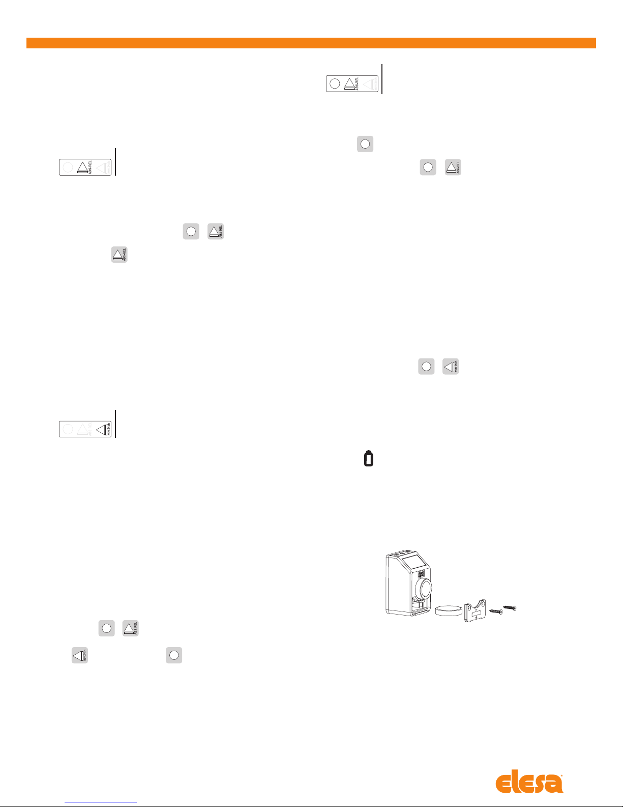
3. Assembly
1. Drill a Ø 6x10 mm hole in the body of the machine with a 22 mm centre
distance from the shaft to fit the
rear referring pin.
2. Fit the indicator onto the shaft and
make sure that the referring pin fits
into the hole.
3. Clamp the bushing to the shaft
by tightening the grub screw with
hexagon socket and cup end,
according to UNI 5929-85.
4. Turning on the system
After you have read and understood the section “Safety Instructions”, proceed
by switching on the indicator.
To turn the indicator on hold while pressing the key .
The display will light up and the indicator will be ready to be used.
4.1 Turning off the system (only for storage)
To turn the system off enter the programming mode, select the
rESEt
parameter then press the key . At this point, press the button for 5
seconds; the display will turn off and the indicator will go into low power mode
of the battery.
5. Symbols on the display
1. Absolute / incremental mode
2. Battery
3. Unit of measure (mm/inch/degrees)
6. Key function
FUNCTION
KEY Operating mode Programming mode
Access to the
programming mode
Parameter selection /
Confirm of parameter change
Absolute or
incremental mode selection
Digit increase /
programming mode exit
Unit of measure selection Scroll for parameters /
digit selection
Models all rights reserved in accordance with the law. Always mention the source when reproducing our drawings.
DD51-E
Direct drive electronic position indicators
7. Operating mode
7.1 Absolute / incremental measuring mode selection
Press the key to select the absolute or incremental measuring mode.
The measuring mode selected is shown on the display by the symbols:
-
ABS
: absolute measuring mode
-
REL
: incremental measuring mode
It is possible to change the key function by setting the
parameter
__0__
The available options are:
-
ArCLr
(default): passing from
ABS
to
REL
the counter is set to zero.
-
Ar
: passing from
ABS
to
REL
the counter is not set to zero. In this case,
the counter is set to zero by pressing + .
-
OFF
: the key is disabled and does not allow changing the selected
measuring mode.
To program the parameters listed above, see paragraph 8.2.
7.2 Unit of measure selection
Press the key to select the unit of measure needed. The options available are
millimeters, inches and degrees.
The measuring mode selected is shown on the display by the symbols:
-
mm
: millimeters
-
INCH
: inches
-
D
: degrees
It is possible to change the key function by setting the
parameter
____0
The available options are:
-
ALL
(default): of measure that can be selected: mm, inch, D
-
nodEG
: of measure that can be selected: mm, inch
-
OFF
: the key is disabled and does not allow changing the selected measuring mode.
To program the parameters listed above, see paragraph 8.2.
7.3 Setting the absolute reference
After having selected the absolute measuring mode and stopped the shaft in
the starting position or in the reference position, press the key combination
to set the absolute value to the sum of the values of the parameters
OrG
(absolute value of reference) and
OFFS
(compensation value).
The value of compensation (offset) allows you to adjust the value shown on the
display in such a way that takes into account, for example, wear or tool change.
The system allows you to store up to 10 values of compensation. Press the key
combination + . The screen will display the last compensation value
used (eg
OFS 0
). Choose the desired compensation value by pressing the
key , and then press the key to confirm.
SThe screen will display the absolute value to the sum of the values of the
parameters
OrG
and
OFFS
.
PTo program the offset values , see parameter
OFFS
of paragraph 8.2.
It is possible to change the function of the keys
combination by setting the parameter
0_0__
The available options are:
-
L_OrG
: the reference value and the compensation value are set as shown
above. Choose the desired offset among the 10 available values, then press
the key to confirm;
-
OFF
: the keys combination + is not associated to any function
in the operating mode
For programming the parameters listed above see paragraph 8.2.
7.4 Direct programming of the absolute reference value (source)
– of the compensation value (offset)
– of the reading after one revolution
The function of the keys combination allows direct access to the programming
of one of the following parameters, depending on the value assigned to
parameter
0___0
.
The available options are:
-
P_OrG
: direct programming of the absolute reference value (
OrG
parameter)
-
P_StP
: direct programming of the reading after one revolution (
StEP
parameter)
-
P_OFS
: direct programming of the compensation value (
OFFS
parameter)
-
OFF
: the keys combination +is not linked to any function in the
operating mode
For programming the parameters listed above see parameter
0___0
of
paragraph 8.2.
7.5 Battery replacement
The internal lithium CR2450 – 3.0 V battery ensures over 5 years battery life.
The symbol is shown on the display when the battery replacement is
required.
The replacement is made by simply removing the front cover without
disassembly of the indicator from the control shaft and keeping unchanged all
the configuration parameters.
To simply remove the battery from the battery compartment, we recommend
the use of a magnet.
__0__
____0
0_0__
Models all rights reserved in accordance with the law. Always mention the source when reproducing our drawings.
DD51-E
Direct drive electronic position indicators
8. Programming mode
Press the key for 3 seconds to enter the programming mode. Depending
on the setting of
PASS
parameter, the system may require you to enter a
password.
Press the key to scroll through the list of parameters.
Press the key to exit the programming mode. The programming mode is
automatically dropped after 30 seconds of inactivity.
8.1 Programming parameters with numeric values
Press the key to increase the flashing digit.
Press the key to select the next digit.
Press the key to confirm the value and go back to the list of parameters.
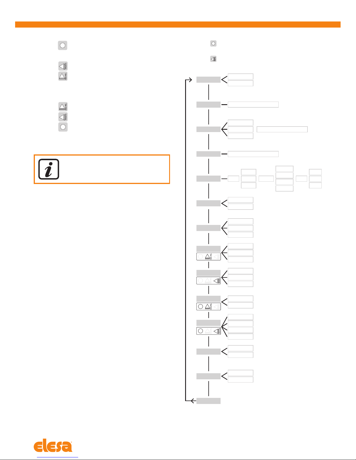
8.2 Programming parameters
Press the key for 3 seconds
Enter the password 22011 (only if
PASS
=
On
)
Press the key to scroll through the list of parameters
rE
SPEEd
300
600
1000
OFFS
OFS 0
... -9999 / 9999
OFS 9
StEP 000.01 / 100.00
rES mm Inch deg
1
0.1
0.01
1
0.1
0.01
1
0.1
0.01
0.001
OrG -9999 / 9999
____0 nodEG
OFF
ALL
diSP 0°
180°
dir --o
o--
PASS On
Off
rESEt No
Yes
0_0__ L_OrG
OFF
__0__ ArCLr
OFF
Ar
0___0
OFF
P_StP
P_OrG
P_OFS
The numeric values of the parameters must be inserted
taking into account the selected unit of measure

Models all rights reserved in accordance with the law. Always mention the source when reproducing our drawings.
DD51-E
Direct drive electronic position indicators
The available parameters and their descriptions are listed in the
following table.
Parameter Description Available
options
Standard
value
dir
Rotation
direction
--o
clockwise
o--
counterclockwise
--o
OrG
Absolute
reference
value
-9999
;
9999
The parameter value depends on the
unit of measure selected.
0
OFFS
Compensation
values
(Offset)
-9999
;
9999
The system allows you to store up to
10 compensation values:
OFS 0
...
OFS 9
The parameter value depends on the
unit of measure selected.
0
StEP
Reading after
one revolution
0.01
;
100.00
001.00
rES
Resolution mm:
1
;
0.1
;
0.01
inches:
0.001
;
0.01
;
0.1
;
1
degrees:
0.01
;
0.1
;
1
mm:
0.1
inches:
0.01
degrees:
1
diSP
Display
orientation
0°
: display right
180°
: display reverse
0°
SPEEd
Reading max
speed [rpm]
300
;
600
;
1000 600
__0__
Key function
ArCLr
: switching from
ABS
to
REL
the counter is set to zero.
Ar
: switching from
ABS
to
REL
the
counter is not set to zero.
OFF
: the key is not assigned to
any function in the operating mode
ArCLr
____0
Key function
ALL
: selectable units of measure:
mm, inch, D
nodEG
: selectable units of measure:
mm, inch
OFF
: the key does not allow the unit
of measure conversion
ALL
0_0__
Key
combination
function
+
L_OrG
: the key combination sets
the absolute value to the sum of
OrG
+
OFFS
parameters
OFF
: lthe key combination is not
assigned to any function in the
operating mode
L_OrG
0___0
Key
combination
function
+
The key combination activates the
direct programming of the following
parameters:
P_OrG
: parameter
OrG
P_StP
: parameter
StEP
P_OFS
: parameter
OFFS
OFF
: lthe key combination is not
assigned to any function in the
operating mode
P_OrG
PASS
Password
ON
: the system requires the password
22011 to enter the programming mode
OFF
: the system does not require a
password to enter the programming
mode
OFF
Parameter Description Available
options
Standard
value
rESEt
Setting of
Parameters
to standard
values
YES
: the parameters are set to the
standard values
NO
: the parameters maintain the
values set by the user
NO
rE
Software
version
The software version is shown on the
display.
9. Problem solving
Message on
the display Description Action
-----
Exceeding the reading scale
(-19999;99999)
The value cannot
be shown on the display.
The system continues to
measure displacements; the
value will be shown on the
display again if re-included in
the reading scale.
S_Err
The shaft speed has exceeded the
max system speed.
Press the key to go back to the
value reading and re-set the
absolute reference.
Flashing
battery symbol
Low Battery Replace the battery
(see paragraph 7.5).
Other manuals for DD51-E
7
Table of contents
Other Elesa Touch Panel manuals


