Elesa DD52R-E User manual

Direct drive electronic
position indicators
2.0 Software Version
Instruction for use
pag. 2
DD52R-E
EN
Instrukcja obsługi
str. 16
PL

EN
DD52R-E
Direct drive electronic position indicators
Models all rights reserved in accordance with the law. Always mention the source when reproducing our drawings.
1. Safety Instructions
The product has been designed and manufactured in
accordance with the current regulations.
The product leaves the factory ready for use and complies
with the safety standards.
To maintain the product in this state, it is necessary that it
is assembled and used properly, in the closest compliance
with this instruction manual and with the following specic
safety precautions.
Ensure that the user has read and understood the instruction
manual and in particular the chapter “Safety Instructions”.
In addition to the instruction manual, all the rules of law
must be observed, in regard to accident prevention and en-
vironmental protection.
This manual is intended as an indispensable supplement to
the existing documentation (catalogues, data sheets and as-
sembly instructions).
The use without complying with the descriptions /
specic parameters, in combination with
systems / machines / processes to be
controlled, it can lead to a malfunction of
the product, causing:
- health hazards,
- environmental hazards,
- damage to the product and its proper functionality.
Do not open nor modify the case of the indicator.
Tampering with this product may endanger the correctness
and accuracy of its operation.
In case of malfunction, do not attempt any repairs to the
units and contact Elesa sales ofce.
2

DD52R-E
Direct drive electronic position indicators
Models all rights reserved in accordance with the law. Always mention the source when reproducing our drawings.
EN
2. System description
DD52R-E position indicators, with battery power supply, can
be used on passing through shafts in any position to provide
the reading of the absolute or incremental positioning of a
machine component.
Mechanical and electrical characteristics
Power supply Lithium battery CR2477 3.0 V
Battery life 8 years
Display 6-digit LCD of 12 mm height
and special characters
Reading scale -199999; 999999
Number of decimal digits programmable (1)
Unit of measure mm, inches, degrees
programmable (1)
Rotation max. speed 300/600/1000 r.p.m. (2)
programmable (1)
Precision 10.000 impulses/revolution
Protection level IP65 or IP67
Working temperature 0° C ÷ +50° C
Storing temperature -20° C ÷ +60° C
Relative humidity max. 95% a 25° C
without condensation
Interference IEC 61000-4-2
(1) See paragraph 8.2
(2) Default: 600 r.p.m.
Higher rotation speeds to 600 r.p.m. can be maintained for short
periods of time.
The value of the max speed affects the battery life.
3
EN
DD52R-E
Direct drive electronic position indicators
Models all rights reserved in accordance with the law. Always mention the source when reproducing our drawings.
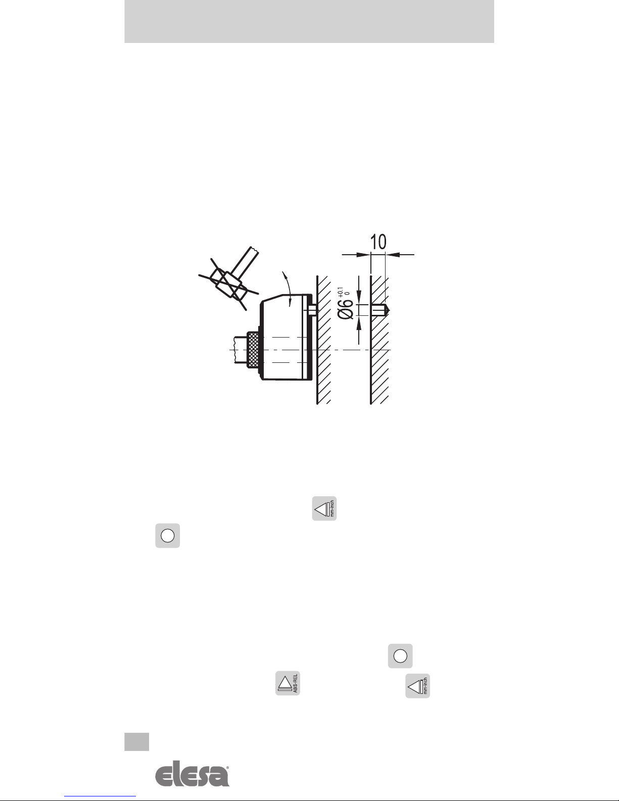
3. Assembly
1. Drill a Ø 6x10 mm hole in the body of the machine with
a 30 mm centre distance from the shaft to t the rear
referring pin.
2. Fit the indicator onto the shaft and make sure that the
referring pin ts into the hole.
3. Clamp the bushing to the shaft by tightening the grub
screw with hexagon socket and cup end, according to
UNI 5929-85.
4. Turning on the system
After you have read and understood the section “Safety
Instructions”, proceed by switching on the indicator.
To turn the indicator on hold while pressing the key
.
The display will light up and the indicator will be ready to
be used.
4.1 Turning off the system (only for storage)
To turn the system off enter the programming mode, select
the
rESEt
parameter then press the key . At this
point, press the button and then press the key;
the display will turn off and the indicator will go into low
power mode of the battery.
4
DD52R-E
Direct drive electronic position indicators
Models all rights reserved in accordance with the law. Always mention the source when reproducing our drawings.
EN
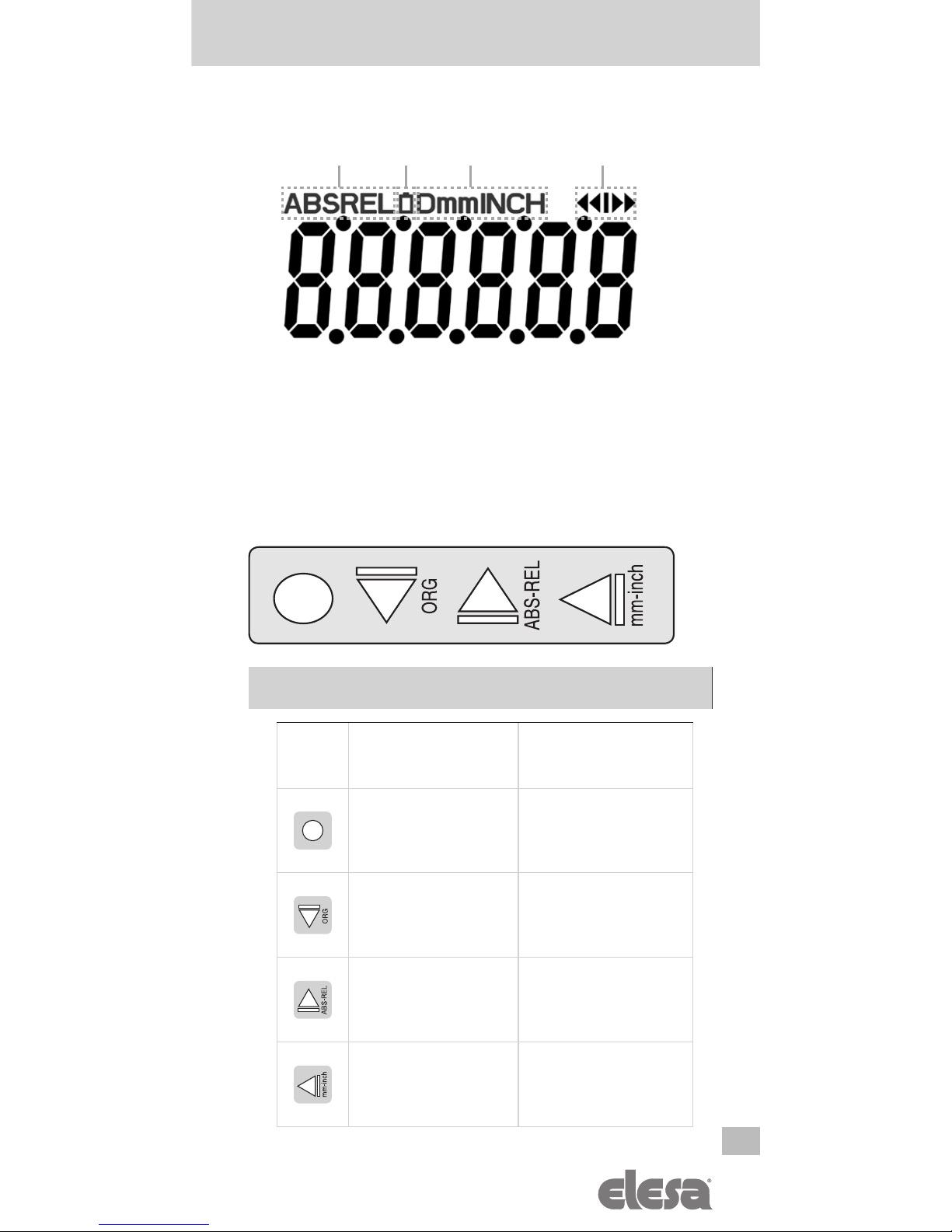
5. Symbols on the display
1. Absolute / incremental mode
2. Battery
3. Unit of measure (mm/inch/degrees)
4. Target position indications
6. Key function
FUNCTION
KEY Operating
mode
Programming
mode
Access to the
programming mode
Parameter selection /
Conrm of parameter
change
Displaying target
position / Distance to
go to target position
Digit decrease /
Scroll for parameters
Absolute or
incremental mode
selection
Digit increase /
Scroll for parameters
Unit of measure
selection
Programming mode
exit /
Digit selection
5
1 2 3 4

EN
DD52R-E
Direct drive electronic position indicators
Models all rights reserved in accordance with the law. Always mention the source when reproducing our drawings.
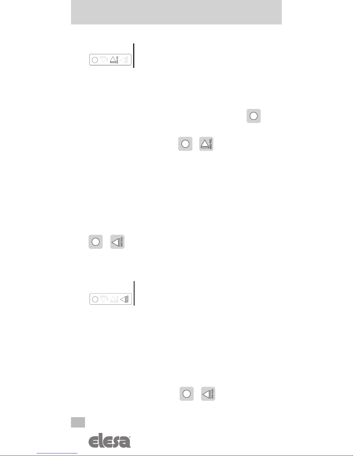
7. Operating mode
7.1 Absolute / incremental measuring mode selection
Press the key to select the absolute or incremental
measuring mode.
The measuring mode selected is shown on the display by
the symbols:
-
ABS
: absolute measuring mode
-
REL
: incremental measuring mode
It is possible to change the key function by
setting the parameter
___0__
The available options are:
-
ArCLr
(default): passing from
ABS
to
REL
the
counter is set to zero.
-
Ar
: passing from
ABS
to
REL
the counter is not set to
zero. In this case, the counter is set to zero by pressing
+ .
-
OFF
: the key is disabled and does not allow
changing the selected measuring mode.
To program the parameters listed above, see paragraph 8.2.
7.2 Unit of measure selection
Press the key to select the unit of measure needed. The
options available are millimeters, inches and degrees.
The measuring mode selected is shown on the display
by the symbols:
-
mm
: millimeters -
INCH
: inches -
D
: degrees
___0__
6

DD52R-E
Direct drive electronic position indicators
Models all rights reserved in accordance with the law. Always mention the source when reproducing our drawings.
EN
It is possible to change the key function by
setting the parameter
_____0
The available options are:
-
ALL
(default): units of measure that can be selected: mm,
inch, D
-
nodEG
: units of measure that can be selected: mm, inch
-
OFF
: the key is disabled and does not allow changing
the selected measuring mode.
To program the parameters listed above, see paragraph 8.2.
7.3 Setting the absolute reference
After having selected the absolute measuring mode and
stopped the shaft in the starting position
or in the reference position, press the key
combination to set the absolute value to the sum of the
values of the parameters
OriGin
(absolute value of
reference) and
OFFSET
(compensation value).
The value of compensation (offset) allows you to adjust the
value shown on the display in such a way that takes into
account, for example, wear or tool change. The system
allows you to store up to 10 values of compensation. Press
the key combination +. The screen will display the
last compensation value used (eg
OFFS 0
). Choose the
desired compensation value by pressing the key , and
then press the key to conrm.
The screen will display the absolute value to the sum of the
values of the parameters
OriGin
and
OFFSET
.
To program the offset values, see parameter
OFFSET
of
paragraph 8.2.
_____0
+
7
EN
DD52R-E
Direct drive electronic position indicators
Models all rights reserved in accordance with the law. Always mention the source when reproducing our drawings.
It is possible to change the function of the
keys combination by setting the parameter
0__0__
The available options are:
-
L_OrG
: the reference value and the compensation
value are set as shown above. Choose the desired offset
among the 10 available values, then press the key
to conrm;
-
OFF
: the keys combination + is not associated
to any function in the operating mode
For programming the parameters listed above see paragraph
8.2.
7.4 Direct programming of the absolute reference value
(source) – of the compensation value (offset) – of the
reading after one revolution
The function of the keys combination allows
direct access to the programming of one of
the following parameters, depending on the value assigned
to parameter
0____0
.
It is possible to change the function of the
keys combination by setting the parameter
0____0
The available options are:
-
P_OrG
: direct programming of the absolute reference
value (OrG parameter)
-
P_StP
: direct programming of the reading after one
revolution (StEP parameter)
-
P_OFS
: direct programming of the compensation value
(OFFS parameter)
-
OFF
: the keys combination +is not linked to
any function in the operating mode
0__0__
+
8
0____0

DD52R-E
Direct drive electronic position indicators
Models all rights reserved in accordance with the law. Always mention the source when reproducing our drawings.
EN
For programming the parameters listed above see parameter
0____0
of paragraph 8.2.
7.5 Programming target position
The function of the keys combination allows, if the parameter
0_0___
has been set on
tArGEt
, to program or to
load one of the 32 target positions.
It is possible to change the function of
the keys combination by setting the
parameter
0_0___
The available options are:
-
LOAd_t
: choose one of the 32 available target
positions, then press to conrm
-
PrOG_t
: choose to program one of the 32 available
target positions, then press to start programming
7.6 Battery replacement
The internal lithium CR2477 – 3.0 V battery ensures over 8
years battery life.
The symbol is shown on the display when the battery
replacement is required.
The replacement is made by simply removing the front cover
without disassembly of the indicator from the control shaft
and keeping unchanged all the conguration parameters.
To simply remove the battery from the battery compartment,
we recommend the use of a magnet.
9
0_0___
EN
DD52R-E
Direct drive electronic position indicators
Models all rights reserved in accordance with the law. Always mention the source when reproducing our drawings.
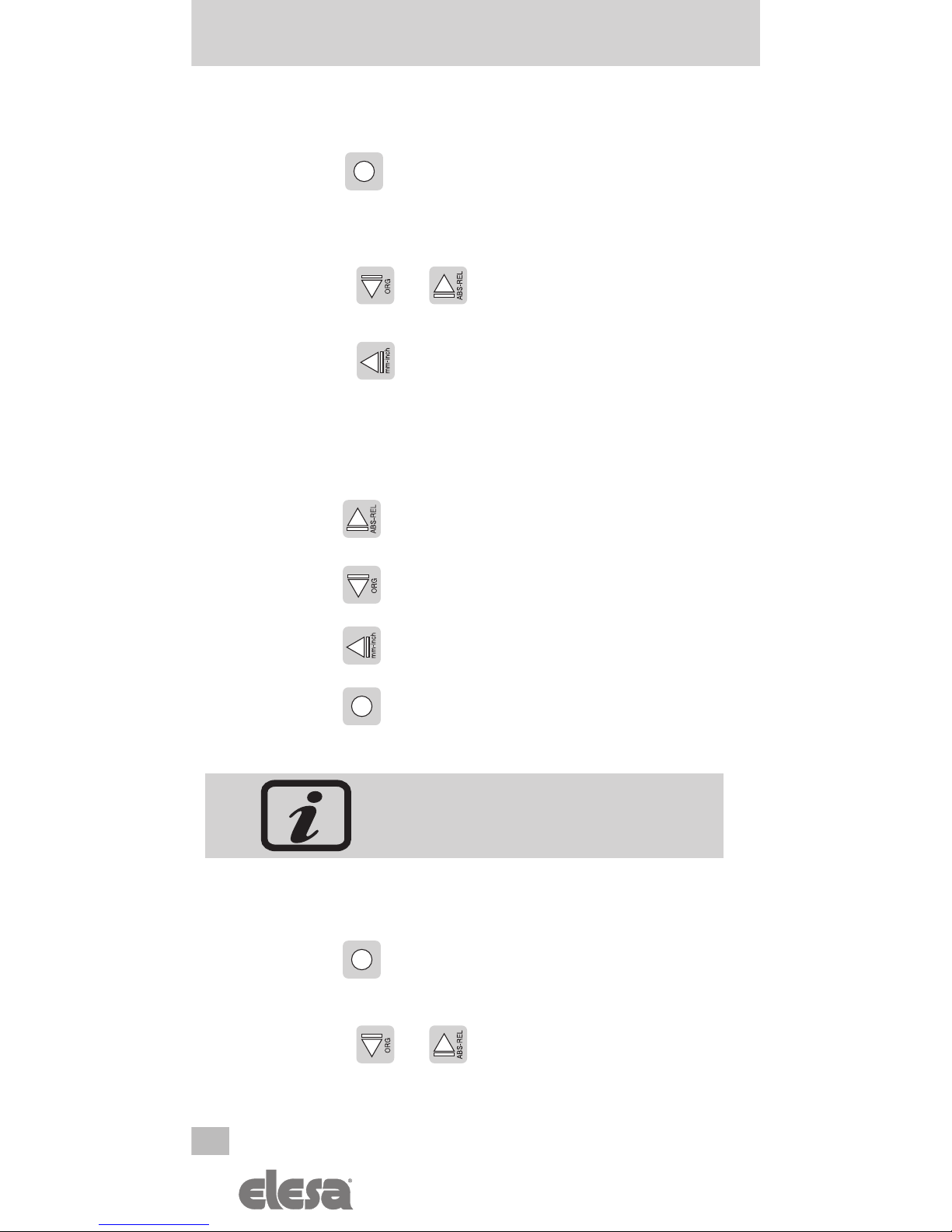
8. Programming mode
Press the key for 3 seconds to enter the programming
mode. Depending on the setting of
PASS
parameter (see
table on page 14), the system may require you to enter a
password.
Press the key or to scroll through the list of
parameters.
Press the key to exit the programming mode. The
programming mode is automatically dropped after 30
seconds of inactivity.
8.1 Programming parameters with numeric values
Press the key to increase the ashing digit.
Press the key to decrease the ashing digit.
Press the key to select the next digit.
Press the key to conrm the value and go back to the
list of parameters.
The numeric values of the parameters
must be inserted taking into account the
selected unit of measure.
8.2 Programming parameters
Press the key for 3 seconds
Enter the password 22011 (only if
PASS
=
On
)
Press the key or to scroll through the list of
parameters.
10

DD52R-E
Direct drive electronic position indicators
Models all rights reserved in accordance with the law. Always mention the source when reproducing our drawings.
EN
11
_____0 nodEG
OFF
ALL
StEP 000.01 / 100.00
OriGin -99999 / 99999
dir --o
o--
diSPL 0°
180°
0__0__ L_OrG
OFF
0____0
OFF
P_StP
P_OrG
P_OFS
PASS On
Off
rESEt No
Yes
OFFSET
OFS 0
... -99999 / 99999
OFS 9
SPEEd
300
600
1000
rES mm Inch deg
1
0.1
0.01
1
0.1
0.01
1
0.1
0.01
0.001
___0__ ArCLr
OFF
Ar
rE
P_toll
__0___
0_0___ tArGEt
OFF
0.01 / 9.99
d_tArG
OFF
d_toG0
The parameter
P_toll
will
appear in the list of parameters
only if the parameter
0
_
0
___
has been set on the option
tArGEt
*
*
EN
DD52R-E
Direct drive electronic position indicators
Models all rights reserved in accordance with the law. Always mention the source when reproducing our drawings.
The available parameters and their descriptions are listed in
the following table.
Parameter Description Available options Standard
value
dir
Rotation
direction
--o
clockwise
o--
counterclockwise
--o
OriGin
Absolute
reference
value
-99999
;
99999
The parameter value
depends on the unit of
measure selected.
0
OFFSET
Compensation
values
(Oset)
-99999
;
99999
The system allows you
to store up to 10
compensation values:
OFS 0
...
OFS 9
The parameter value
depends on the unit of
measure selected.
0
StEP
Reading
after one revolution
0.01
;
100.00
001.00
rES
Resolution mm:
1
;
0.1
;
0.01
inches:
0.001
;
0.01
;
0.1
;
1
degrees:
0.01
;
0.1
;
1
mm:
0.1
inches:
0.01
degrees:
1
diSPL
Display orientation
0°
: display right
180°
: display reverse
0°
SPEEd
Reading max speed
[rpm]
300
;
600
;
1000 600
P_toll
Tolerance of target
position
0.01
;
9.99
The parameter value
depends on the unit of
measure selected.
0.05
_____0
Key function
ALL
: selectable units of
measure: mm, inch, D
nodEG
: selectable units of
measure: mm, inch
OFF
: the key does not
allow the unit of measure
conversion
ALL
12

DD52R-E
Direct drive electronic position indicators
Models all rights reserved in accordance with the law. Always mention the source when reproducing our drawings.
EN
Parameter Description Available options Standard
value
___0__
Key function
ArCLr
: switching from
ABS
to
REL
the counter
is set to zero.
Ar
: switching from
ABS
to
REL
the counter is not
set to zero.
OFF
: the key is not
assigned to any function in
the operating mode.
ArCLr
__0___
Key function
d_tArG
: during the
positioning press the key
on the display will
appear the target position
to reach.
d_toG0
: during the
positioning press the key
on the display will
appear the distance to reach
the target position.
OFF
: the key is not
assigned to any function in
the operating mode.
OFF
0____0
Key
combination
function
+
The key combination
activates the direct
programming of the
following parameters:
P_OrG
: parameter
OrG
P_StP
: parameter
StEP
P_OFS
: parameter
OFFS
OFF
: the key combination
is not assigned to any
function in the operating
mode.
P_OrG
13

EN
DD52R-E
Direct drive electronic position indicators
Models all rights reserved in accordance with the law. Always mention the source when reproducing our drawings.
Parameter Description Available options Standard
value
0__0__
Key
combination
function
+
L_OrG
: the key
combination sets the
absolute value to the
sum of
OrG
+
OFFS
parameters.
OFF
: the key combination
is not assigned to any
function in the operating
mode.
L_OrG
0_0___
Key
combination
function
+
tArGEt
: the keys
combination allows to load/
program on of the 32 target
positions.
OFF
: the key is not
assigned to any function in
the operating mode.
OFF
PASS
Password
ON
: the system requires the
password 22011 to enter the
programming mode.
OFF
: the system does not
require a password to enter
the programming mode.
OFF
rESEt
Setting of
parameters to
standard values
YES
: the parameters are
set to the standard values.
NO
: the parameters
maintain the values set by
the user.
NO
rE
Software version The software version is
shown on the display.
F 2.0
14

DD52R-E
Direct drive electronic position indicators
Models all rights reserved in accordance with the law. Always mention the source when reproducing our drawings.
EN
9. Problem solving
Message on the
display Description Action
------
Exceeding the
reading scale
(-19999;99999)
The value cannot
be shown on the
display.
The system
continues to
measure
displacements;
the value will be
shown on the display
again if re-included
in the reading scale
S_Err
The shaft speed has
exceeded the max
system speed
(see table on
page 26).
Press to
go back to the
value reading and
re-set the absolute
reference.
Flashing
battery symbol
Low Battery Replace the battery
(see paragraph 7.6).
15

EN
DD52R-E
Direct drive electronic position indicators
Models all rights reserved in accordance with the law. Always mention the source when reproducing our drawings.
1. Instrukcja bezpieczeństwa
Produkt ten został zaprojektowany i wyprodukowany
zgodnie z ogólnie przyjętymi procesami technologicznymi.
Produkt opuszcza fabrykę w pełnej gotowości do pracy,
spełniając wszelkie normy bezpieczeństwa. Aby nie utracił
podanych właściwości, konieczna jest poprawna instalacja
i obsługa urządzenia, zgodnie z podanymi w instrukcji
zasadami użytkowania i bezpieczeństwa.
Należy upewnić się, że użytkownik przeczytał i zrozumiał
niniejszą instrukcję, a w szczególności rozdział Wskazówki
bezpieczeństwa.
Ponadto, należy przestrzegać ogólnie przyjętych i prawnie
nakazanych norm bezpieczeństwa i ochrony środowiska.
Instrukcja ta jest dodatkiem do istniejących już materiałów
(katalog, arkusz z danymi i instrukcja montażu).
Działania niepokrywające się z
wyszczególnionymi opisami / parametrami,
w połączeniu z systemami/ maszynami/
procesami wymagającymi kontroli/
monitorowania są niewłaściwe i mogą prowadzić do:
- Uszczerbku na zdrowiu
- Zagrożenia dla środowiska
- Uszkodzenia urządzenia i jego niewłaściwego
funkcjonowania
Nie należy otwierać obudowy wskaźnika lub jej modykować.
Manipulowanie przy wskaźniku może mieć wpływ na jego
dokładność i prawidłowość działania.
W przypadku niewłaściwego działania nie należy dokonywać
samodzielnych napraw, lecz skontaktować się z biurem
sprzedaży Elesa.
16
PL
Elektroniczne wskaźniki położenia z napędem
bezpośrednim
Wzory Elesa, wszelkie prawa zastrzeżone
.

DD52R-E
Direct drive electronic position indicators
Models all rights reserved in accordance with the law. Always mention the source when reproducing our drawings.
EN
2. Opis systemu
Elektroniczne wskaźniki położenia DD52R-E zasilane
baterią mogą być montowane na wałkach sterowniczych
w dowolnej orientacji, pozwalając na odczyt bezwzględnej
i przyrostowej pozycji części urządzenia.
Właściwości mechaniczne i elektryczne
Zasilanie bateria litowa CR2477
3.0 V
Żywotność
baterii 8 lat
Wyświetlacz
Sześciocyfrowy ekran LCD,
wyświetlający cyfry 12
mm wysokości oraz znaki
specjalne
Zakres odczytu -199999; 999999
Dokładność programowalna (1)
Jednostki miary milimetry, cale, stopnie,
programowalne (1)
Maks. prędkość obrotowa 300/600/1000 obr/min (2)
programowalna (1)
Precyzja 10.000 impulsów/obrót
Stopień ochrony IP65 lub IP67
Temperatura pracy 0° C ÷ +50° C
Temperatura przechowywania -20° C ÷ +60° C
Wilgotność względna
max. 95% przy 25° C
bez kondensacji pary
wodnej
Ochrona przeciwzakłóceniowa IEC 61000-4-2
(1) Patrz punkt 8.2
(2) Domyślnie 600 obr/min. Wyższa prędkość obrotowa jest możliwa przez
krótki czas. Wartość prędkości obrotowej ma wpływ na żywotność
baterii.
17
PL
Elektroniczne wskaźniki położenia z napędem
bezpośrednim
Powielanie naszych rysunków zawsze z podaniem żródła pochodzenia.

EN
DD52R-E
Direct drive electronic position indicators
Models all rights reserved in accordance with the law. Always mention the source when reproducing our drawings.
3. Instrukcja montażu
1. W korpusie maszyny wywiercić otwór pod tylny kołek
wskaźnika (średnica 6 mm, głębokość 10 mm, odległość
od osi wałka 30 mm).
2. Zamocować wskaźnik na wałku i upewnić się, że kołek
znajduje się w otworze. Uwaga: Wskaźnik na wałek
należy wsuwać trzymając za jego stalową tuleję!
3. Zacisnąć tuleję na wałku za pomocą wkrętu z gniazdem
sześciokątnym, zgodnie z UNI 5929-85.
4. Uruchomienie
Po zapoznaniu się z Instrukcją Bezpieczeństwa należy włączyć
wskaźnik.
W tym celu należy wcisnąć jednocześnie oraz .
Wyświetlacz podświetli się i wskaźnik będzie gotowy do
pracy.
4.1 Wyłączanie systemu (w przypadku magazynowania)
Aby wyłączyć system należy wejść w tryb programowania,
wybrać parametr
rESEt
a następnie wcisnąć przycisk .
Następnie, przytrzymując przycisk wcisnąć przycisk
Wyświetlacz wyłączy się, a wskaźnik przejdzie w tryb
oszczędzania baterii.
18
PL
Elektroniczne wskaźniki położenia z napędem
bezpośrednim
Wzory Elesa, wszelkie prawa zastrzeżone
.

DD52R-E
Direct drive electronic position indicators
Models all rights reserved in accordance with the law. Always mention the source when reproducing our drawings.
EN
5. Symbole na wyświetlaczu
1. Tryb bezwględny/przyrostowy
2. Bateria
3. Jednostka miary (mm/cale/stopnie)
4. Wskaźnik pozycji docelowej
6. Funkcje przycisków
FUNKCJE
PRZYCISK Tryb pracy Tryb
programowania
Wejście w tryb progra-
mowania
Wybór parametrów/potwierdze-
nie zmiany parametru
Wyświetlanie wartości
pozycji docelowej /
Dystansu do pozycji
docelowej
Zmniejszenie wartości liczbowej /
Przewijanie listy parametrów
Wybór trybu
bezwzględnego lub
przyrostowego
Zwiększenie wartości/Przewijanie
listy parametrów
Wybór jednostki miary
Wyjście z trybu
programowania /
Przesuwanie w
celu wyboru cyfry
19
PL
Elektroniczne wskaźniki położenia z napędem
bezpośrednim
Powielanie naszych rysunków zawsze z podaniem żródła pochodzenia.
1 2 3 4

EN
DD52R-E
Direct drive electronic position indicators
Models all rights reserved in accordance with the law. Always mention the source when reproducing our drawings.
7. Obsługa w trybie pracy
7.1 Wybór bezwzględnego/przyrostowego trybu pracy
Wciśnij przycisk aby wybrać bezwzględny lub
przyrostowy tryb pracy.
Wybrany tryb jest sygnalizowany na wyświetlaczu symbolami:
-
ABS
: bezwzględny tryb pracy
-
REL
: przyrostowy tryb pracy
Możliwa jest zmiana funkcji przycisku w
ustawieniach parametru
___0__
w
trybie programowania
Opcje dostępne w trybie programowania:
-
ArCLr
(domyślnie): przy przejściu z
ABS
na
REL
licznik jest zerowany.
-
Ar
: przy przejściu z
ABS
na
REL
licznik nie jest
zerowany. W tym wypadku licznik jest zerowany za
pomocą kombinacji przycisków + .
-
OFF
: przycisk jest nieaktywny i zmiana trybu pracy
nie jest możliwa.
Aby zaprogramować parametry wymienione powyżej, patrz
punkt 8.2
7.2 Wybór jednostki miary
Naciśnij przycisk , aby wybrać potrzebną jednostkę
miary. Dostępne jednostki to milimetry, cale i stopnie.
Wybrana jednostka miary pojawia się na wyświetlaczu jako:
-
mm
: milimetry -
INCH
: cale -
D
: stopnie
___0__
20
PL
Elektroniczne wskaźniki położenia z napędem
bezpośrednim
Wzory Elesa, wszelkie prawa zastrzeżone
.
Other manuals for DD52R-E
3
Table of contents
Languages:
Other Elesa Touch Panel manuals


