Novus N1500 User manual

NOVUS AUTOMATION 1/7
Indicator
N1500
UNIVERS
AL PROCESS INDICATOR – INSTRUCTIONS MANUAL – V2.3 G
SAFETY SUMMARY
The symbols below are used on the equipment and throughout this
document to draw the user’s attention to important operational and
safety information.
CAUTION or WARNING:
Read complete instructions prior
to installation and operation of the
unit.
CAUTION or WARNING:
Electrical Shock Hazard
All safety related instructions that appear in the manual must be
observed to ensure personal safety and to prevent damage to either
the instrument or the system. If the instrument is used in a manner
not specified by the manufacturer, the protection provided by the
equipment may be impaired.
PRESENTATION
N1500 is a universal process indicator which accepts a large variety
of input signals and sensors. A six-digit LED display shows measured
value and all programming parameters.
Instrument configuration is achieved from the keypad, without any
hardware change. Thus, the selection of input type and alarms
modes, besides other special functions, are accessed and defined
from the frontal keypad.
The user should read this manual thoroughly before using the
instrument. It must be handled with care and should be used
accordingly for best results.
Some of the features are:
•Universal input: Pt100, thermocouples, 4-20 mA, 0-50 mV, 0-5 V
and 0-10 V.
•24 Vdc power supply for remote transmitter excitation
•Memory for maximum and minimum values.
•Hold and peak hold functions.
•Digital Input;
•Increasing or decreasing display;
•Process Variable (PV) retransmission in 0-20 mA or 4-20 mA
(optional).
•RS485 MODBUS RTU serial communication (optional).
•3rd and 4th alarm relays (optional).
PROCESS VARIABLE INPUT - PV
The process variable (PV) input type is configured through the frontal
keypad according to the codes shown in Table 1 (refer to INPUT
TYPE parameter "
in.typ
").
All input types are factory calibrated and no additional calibration is
required.
TYPE CODE MEASURING RANGE
J
Tc j
Range: -130 to 940 °C (-202 to 1724 °F)
K
Tc h
Range: -200 to 1370 °C (-328 to 2498 °F)
T
Tc t
Range: -200 to 400 °C (-328 to 752 °F)
E
Tc e
Range: -100 to 720 °C (-148 to 1328 °F)
N
Tc n
Range: -200 to 1300 °C (-328 to 2372 °F)
R
Tc r
Range: 0 to 1760 °C (32 to 3200 °F)
S
Tc s
Range: 0 to 1760 °C (32 to 3200 °F)
B
Tc b
Range: 500 to 1800 °C (932 to 3272 °F)
Pt100
Pt100
Range: -200.0 to 850.0 °C (-328.0 to 1562.0 °F)
0–50Mv
Linear
0-50
Linear. Scalable from -31000 to 31000
0–5V
Linear
0-5
Linear. Scalable from -31000 to 31000
0-10V
Linear
0-10
Linear. Scalable from -31000 to 31000
0–50mV
No Linear
c.0-50
Custom Linearization, user configurable
0–5V
No Linear
c.0-5
Custom Linearization, user configurable
0-10V
No Linear
c.0-10
Custom Linearization, user configurable
4-20 mA
NO
LINEAR
Lin J
T/C type J linearization. Range: -130 to 940 °C
LIn h
T/C type K linearization. Range: -200 to 1370 °C
LIn t
T/C type T linearization. Range: -200 to 400 °C
LIn e
T/C type E linearization. Range: -100 to 720 °C
LIn n
T/C type N linearization. Range: -200 to 1300 °C
LIn r
T/C type R linearization. Range:0 to 1760 °C
LIn s
T/C type S linearization. Range:0 to 1760 °C
LIn b
T/C type B linearization. Range:500 to 1800 °C
Linpt
Pt100 linearization. Range:-200.0 a 850.0 °C
0-20 Ma
Linear
0-20
Linear. Scalable from -31000 to 31000
4-20 mA
Linear
4-20
Linear. Scalable from -31000 to 31000
0-20 mA
No Linear
c.0-20
Custom Linearization, user defined
4-20 mA
No Linear
c.4-20
Custom Linearization, user defined
Table 1 - Input type codes

Indicator N1500
NOVUS AUTOMATION 2/7
ALARMS
The indicator has 2 alarm outputs in the basic version and up to 4
alarms outputs optionally.
Each alarm has a corresponding LED message in the front panel to
show alarm status.
ALARM FUNCTIONS
The alarms can be set to operate in seven different modes. These
modes are shown in Table 2 and described below. The alarm can
also be set as ‘disabled’.
•Sensor break -
Ierr
The alarm is triggered whenever the sensor breaks or is badly
connected.
•Low alarm -
Lo
The alarm relay is triggered whenever the measured value is below
the alarm set point.
•High alarm -
Ki
The alarm relay is triggered whenever the measured value is above
the alarm set point.
•Differential low –
Dif.lo
Deviation alarm. Alarm relay is triggered whenever the difference
(deviation) between the Process Variable and the reference value
(
AlrEF
) is lower than the values defined in
SP.AL
. For this function,
the triggering point is defined as:
(
ALrEF
–
SP.AL
)
•Differential High –
Dif.ki
Deviation alarm. Alarm relay is triggered when the difference
(deviation) between the Process Variable value and the reference
value (
AlrEF
) is greater than the value defined in
SPAL
. For this
function, the triggering point is defined as:
(
ALrEF
+
SP.AL
)
•Differential (or Band) out of range –
Dif.ov
Deviation alarm. Alarm relay is triggered when the difference
(deviation) between the Process Variable value and the reference
value (
AlrEF
) has its modulus greater than the value configured in
SPAL
. For this function, the triggering point is defined as:
(
ALrEF
–
SP.AL
) and (
ALrEF
+
SP.AL
)
•Differential (or Band) within range –
Dif.In
Deviation alarm. Alarm relay is triggered when the difference
(deviation) between the Process Variable value and the reference
value (
AlrEF
) has its modulus lower than the value defined in
SPAL
. For this function, the triggering points are defined as:
(
ALrEF
–
SP.AL
) and (
ALrEF
+
SP.AL
)
TYPE
PROMPT
ACTION
Disabled
Off
Alarm is inactive
Sensor Break
(input Error)
Ierr
Alarm will go ON if sensor breaks
Low Alarm
(Low)
Lo
Alarm SP
PV
High Alarm
(High)
Ki
Alarm SP
PV
Differential Low
(differential Low)
Dif.lo
PV
AL SP + Deviation
AL SP
Differential High
(differential High)
Dif.ki
PV
AL SP + Deviation
AL SP
Differential out of
range
(differential out)
Dif.ov
PV
AL SP + Deviation
Positive Deviation
AL SP
AL SP - Deviation
Differential within
range
(differential Within)
Dif.In
PV
AL SP + Deviation
Negative Deviation
AL SP
AL SP - Deviat.
Table 2 - Alarm functions
ALARM TIMER
The alarms can be configured to perform timing functions. The
configuration allows the alarm output to be delayed, or to deliver a
single pulse or a train of pulses. The delay, the pulse width and the
period are defined by the user.
Table 3 shows these advanced functions. Times T1 and T2 can be
programmed from 0 to 6500 seconds. Programming 0 (zero) in the
timer parameters T1 and T2 disables the timer function.
The leds associated with the alarm always light up when the alarm
condition occurs, regardless of the current state of the output relay,
which may be de-energized momentarily due to a time delay.
Advanced
Function T1 T2 ACTION
Normal
Operation 0 0
Alarm Event
Alarm
Output
Delayed 0 1 sto
6500 s
Alarm Event
Alarm
Output
T2
Pulse 1 s to
6500 s 0
Alarm Event
Alarm
Output
T1
Oscillator 1 s to
6500 s 1 s to
6500 s
Alarm Event
Alarm
Output
T1
T2
T1
Table 3 - Timer alarm functions
ALARM INITIAL BLOCKING
The initial blocking option inhibits the alarm from being recognized if
an alarm condition is present when the controller is first energized.
The alarm will be triggered only after the occurrence of a non alarm
condition followed by a new occurrence for the alarm.
The initial blocking is disabled for the sensor break alarm function.
SPECIAL FUNCTIONS
MAXIMUM AND MINIMUM
The indicator memorizes the measured maximum and minimum
values (peak and valley). These two values are shown when pressing
the MAX or MIN keys. Pressing both keys simultaneously will clear
the memory for a new peak and valley detection.
SPECIAL FUNCTION KEY AND DIGITAL INPUT
The key (special function key) in the frontal panel and the
optional digital input can execute special functions according to the
user selection. Fig. 8 shows how to activate the digital input. The
special functions for the key and for the digital input are
explained as it follows.
•
Kold
- Freeze measured value
The hold function freezes the measured value showed in the display.
This function is toggled each time the key is pressed or the
digital input is selected.
Whenever the indicator is in the hold mode a “
koLd
”message is briefly
displayed to show the operator that the displayed value is the frozen
value and not the current input reading.
•
Pkold
– Maximum value
The Peak Hold function shows the maximum value measured since
the last time the F key was pressed or the digital input activated.
Each activation of the key or digital input triggers a new Peak
Hold level and the display resets with a new peak value.
•
rSt
- Clears maximum and minimum
This function works the same way as the MAX and MIN keys pressed
simultaneously, as explained in the 5.1 section. If this “
rSt
” function
is programmed, every touch of the key or activation of the digital
input will clear the memory and a new level of maximum and
minimum values memorization will start.

Indicator N1500
NOVUS AUTOMATION 3/7
PROCESS VARIABLE RETRANSMISSION
As an option, the indicator can be supplied with an isolated 0-20 mA
or 4-20 mA analog output for Process Variable (PV) retransmission.
The PV values that define the scale of the 0 mA / 4 mA to 20 mA
retransmission can be programmed by the user in the high and low
output limits (
0v.lol
e
0v.kol
), at configuration level. High and
low limits can be freely programmed, even with a low limit higher than
high limit, resulting in a reversed retransmission signal (decreasing
signal when PV increases).
When this option is available, retransmission will be always active, so
that the user will not be required to turn it on or off.
For a voltage output signal an external shunt (calibrated resistor)
should be installed at the analog output terminals.
AUXILIARY 24 VDC POWER SUPPLY – AUXILIARY P.S.
The indicator provides a voltage power supply of 24 Vdc to excite
field transmitters with 25 mA current capacity. Available at the back
panel terminals 16 and 17.
CUSTOMIZED LINEARIZATION.
Three types of signals can be user-customized to fit particular
linearization profiles. This means that the operator can configure the
instrument to read non-standard crescent non-linear signals with high
accuracy.
INSTALLATION
The indicator is designed to be panel mounted. Remove the two plastic
fixing clamps from the instrument, insert the unit into the panel cut-out
and slide firmly the fixing clamps from the rear against the panel.
RECOMMENDATIONS FOR INSTALLATION
•Input signal wires should be laid out away from power lines and
preferably inside grounded conduits.
•Instrument mains (line) supply should be suitable for this purpose
and should not be shared.
•In controlling and monitoring applications, possible consequences
of any system failure must be considered in advance. The internal
alarm relay does not warrant total protection.
•Use of RC filters (47 R and 100 nF, serial) are highly
recommended when driving solenoids, contactor coils or other
inductive loads.
ELECTRICAL CONNECTIONS
The internal electronics can be removed from the front panel without
any cable disassembly. The input signals and power connections are
shown in Fig. 1.
Fig. 1 – Back Panel Terminals
POWER CONNECTION
Fig. 2
– Power Connection
SENSOR AND INPUT SIGNAL CONNECTIONS
These connections should be properly done and terminals must be
well tightened. Thermocouples must be installed with proper
extension or compensation cables.
Pt100 RTDs must be 3-wire connected and the wires connected to
terminals 22 and 23 should have the same electrical resistance
(same wire gauge) for correct cable length compensation. Four-wire
RTDs can be connected by disconnecting the fourth wire. Two-wire
RTDs can be connected by shortening terminals 22 and 23 and
connecting the Pt100 to terminals 23 and 24.
The figures below show the connections relative to each type of input.
Fig. 3 – Thermocouple input Fig. 4 – 3 wire Pt100 input
Fig. 5 – Voltage input Fig. 6 – Current input
Fig. 7 – Connection for 0-5 V or 0-
10 V Fig. 8 – Digital Input
Fig. 10 shows the connections for a 4-20 mA transmitter powered by
the 24 V power supply of the indicator.
Fig. 9 – Two-wire transmitter with internal power supply
DIGITAL INPUT (DIG IN)
The digital input is activated by connecting a switch (or equivalent) to
its terminals, as shown in Fig. 8 above.
ANALOG OUTPUT
The N1500 can deliver either 0-20 mA or 4-20 mA analog output,
depending on how the instrument is configured. The output is
available at terminals 29 and 30.

Indicator N1500
NOVUS AUTOMATION 4/7
OPERATION
The front panel is shown below.
Fig. 10 - Front panel identification
Status Display: Shows the process variable (PV) and the
programming prompts.
Indicators A1, A2, A3 and A4: show active alarms.
Indicators Rx and Tx: indicate RS485 communication line is active.
PROGRAM key - This key is used to access different
displays with the programmable parameters of the device.
BACK key - This key is used to go back to the previous
parameter displayed in the menu level.
UP / MAX and DOWN / MIN key –It is used to
increase and decrease parameters values. These keys are
also used to display maximum and minimum values stored
in memory.
FUNCTION key - This special function key is used for pre-
programmed functions as explained in the special function key
section of this manual.
The indicator requires that the internal parameters be properly
configured such as to fit the application need. These parameters are
the input type (T/C, Pt100, 4-20 mA, etc), alarms triggering points,
alarm functions, etc.
These parameters are divided in five levels (or groups) of parameters
which we will refer to as LEVELS.
LEVEL ACCESS
1- Work Free access
2- Alarms
Reserved access
3- Functions
4- Configuration
5- Customized Linearization
6- Calibration
Table 4 - ParametersLevels
The work level has free access. All other levels require a certain
combination of key strokes to be accessed. The combination is:
and keys pressed simultaneously
Once within a level, just press to move to the subsequent
parameters of this level. At the end of each level the display will go
back to the work level.
NOTE: In order to access the calibration level, however, it’s required
to press the keys and simultaneously for 10 seconds. The
first parameter in this level is presented (
In.LoC
) indicating that the
calibration level is enabled.
After reaching the intended prompt just press the or keys to
change this parameter accordingly. All changes are recorded in non-
volatile memory as we move to next prompt. After 25 seconds with no
key pressed the indicator will return to the measuring level (work level).
CONFIGURATION PROTECTION
As safety measure, parameter changes can be prevented by a
combination of keys, valid for each level. The protected parameters
can be inspected but not modified.
To protect a level press the and keys simultaneously for 3
seconds while in the level. To unlock the level, press and
for 3 seconds.
The display will briefly flash confirming that the level was
successfully locked or unlocked.
For further protection, the keypad unlock operation can be disabled
by changing the position of an internal strap inside the indicator:
When PROT is OFF, the user is allowed to lock and unlock the levels
using the keypad as explained above. If PROT is ON, the levels
lock/unlock operation is disabled.
PROGRAMMING THE INDICATOR
WORK LEVEL
This is the first level. At power up the indicator will display the Process
Variable (PV). The alarm triggering points are also displayed at this level
(alarm Setpoints). To advance in this level simply press .
SCREEN PROMPT PARAMETER DESCRIPTION
8.8.8.8.8.
PV Measurement. Shows the measured
variable. For
Pt100 or thermocouples the display will show the absolute
temperature value.
For 4-20 mA, 0-50 mV, 0-5 V and 0-10 mV inputs the
display shows the values defined in the “
in.LoL
” and
“
in.kiL
” parameters.
With the hold function programmed the display shows the
frozen variable and alternates with the message “
koLd
”.
Likewise, with Peak Hold function programmed the high
limitisdisplayed with the “
P.koLd
” prompt alternately.
Should any fault situation occur the indicator will display an
error message which can be identified at item 10 of this
manual.
Al.ref
Differential Alarm Reference Value -
This prompt is
shown only when there is an alarm programmed with
differential function. This value is used as a reference for
differential alarms triggering.
Sp.al1
Sp.al2
Sp.al3
Sp.al4
Alarms Set Points 1, 2, 3 and 4 - Defines the operation
point of each alarm programmed with “
Lo
” or “
ki
”
functions.
When an alarm is programmed with a differential function,
the alarm setpoint value represents the deviation value of
the alarmrelative to the reference
Al.ref
.
ALARM LEVEL
fV.al1
fV.al2
fV.al3
fV.al4
Alarm Function - Defines functions for the alarms 1, 2, 3
and 4.
oFF
: Alarm off
iErr
: Broken or Shorted Sensor
Lo
: Low value
ki
: High value
DiF.Lo
: Differential low
DiF.Hi
: Differential high
DiF.ov
: Differential outside the range
DiF.in
: Differential within range
Ky.al1
Ky.al2
Ky.al3
ky.al4
Alarm Hysteresis
This is the difference from the measured value to the point
where the alarm isturned ON and OFF.
Bl.al1
Bl.al2
Bl.al3
bl.al4
Alarm Blocking
Should any alarm condition occur, the alarms can be
individuallydisabled when energizing the indicator.

Indicator N1500
NOVUS AUTOMATION 5/7
Al1t1
Al1t2
Al2t1
Al2t2
Al3t1
Al3t2
Al4t1
Al4t2
Alarm Timer
The user can set delayed, momentary or sequential alarms
by configuring timesT1 and T2 according to Table 3.
To disable thisfunction just setzero for T1 and T2.
FUNCTION LEVEL
f.fvnc
KEY FUNCTION – Defines functions for the
key. The available optionsare:
oFF
- Key not used.
Hold
- Hold PV
RSt
- ResetsPeak and Valley (MAX and values)
P.koL - Peak Hold
Dig.in
Digital Input Function – Defines the function forthe digital
input. Refer to item 5.2. Options are:
oFF
-
kold
-
rSt
-
PkoLd
filtr
Input Digital Filter
- Adjustable from 0 to 60, this is used
to reduce instability of the measured value. 0 means the
filter is off and 60 means maximum filtering.The higher the
filter value, the slower the response.
ofset
Display Offset - This a value which is added to the PV to
offset any measurement deviation or sensor error. The
offset isshown in the programmed engineeringunit.For °F
measurements the null reference is at 32 °F.
bavd
Baud Rate - Serial digital communication speed in bps.
Programmable:
1200, 2400, 4800, 9600, 19200, 38400, 57600, 115.2. (no
parity) 1.2P, 2.4P, 4.8P, 9.6P, 19.2P, 38.4P, 57.6P and
115.2P (with EVEN parity).
Adres
Communication Address - A number that identifies the
instrument in a multidrop network.
CONFIGURATION LEVEL
In.typ
Input Type - Selects the input signal or sensor type to be
connectedto the PV terminals.RefertoTable 1 foroptions.
Changing the input type causes all other parameters
related to PV and alarms to be changed as well, therefore,
thisparametershallbe the firstto be set.
Dp.pos
Decimal Point Position -
Defines the decimal point
position in the displayed value. It is displayed when linear
input types 0-50 mV, 4-20 mA, 0-5 V or 0-10 V are
selected at the “
in.tYP
” prompt.
Vnit
Temperature Unit - Selects °C or °F indication. This prompt
is not shown for input types0-50 mV, 4-20 mA, 0-5 V or 0-10
Vare selectedatthe“
in.tYP
” prompt.
s.root
Square Root - This prompt is only shown when input types
0-50 mV, 4-20 mA and 0-5 V are selected at the “
in.tYP
”
prompt.
Set “
YES
” and the square root will be applied to the
measured value within the limits programmed in “
in.LoL
”
and “
in.kiL
”.
The display will show the low limit (
in.LoL
) value should
the input signal be below 1 % of the range.
Scale
Scale
- Defines the indication range for linear inputs (0-50
mV, -20 mA, 0-5 V and 0-10 V).
0
Configurable indication from – 31000 to +31000.
1
Configurable indication from 0 to +60000.
2
Configurable indication from 0 to +120000. Only even
valueswillbe displayed (resolution isnot improved).
The selected s
cale affects values of PV, alarm setpoints
and Offset.
In.lol
Input Low Limit - Sets the low limit for input type 0-50 mV,
4-20 mA, 0-5 V or 0-10 V. When the PV Retransmission
is used this limit defines the corresponding 4 mA (or 0 mA)
in relation to the input value.
In.kil
Input High Limit - Sets the high limit for input type 0-50
mV, 4-20 mA, 0-5 V or 0-10 V. When the PV
Retransmission
is used this limit defines the
corresponding 20 mA in relation to the input value.
Ou.lol
Low Limit for Analog Retransmission
– Defines the PV
valuethatresultsina4 mA (or0mA)analogoutputcurrent.
Ou.kil
High Limit for Analog Retransmission
– Defines the PV
value that resultsin a 20 mA analog output current.
Ovt.ty
Analog Output Type
- Selects the analog output type to
either 0- 20 mA or 4-20 mA.
Ovt.er
4-20 mA Output behavior in case of failures – Defines the
outputas4-20 mA whenthere is anerror in the indication.
Do
– Appliesa value < 4mA;
UP
– Applies avalue> 20mA
CUSTOMIZED LINEARIZATION LEVEL
Inp.01
Inp.30
Defines the initial and end analog input values for each
custom segment line. The values must be entered in the
input signal unit:
0-50 mV, 4-20 mA or 0-5 V. For 0-10 V select 0-5 V.
Ovt.01
ovt.30
Defines the corresponding indication that each custom
segment is to show. Values are expressed in the desired
indication unit (within the Indication Lower and Upper
Limits).
Table 5 shows the sequence of levels and parameters presented in the indicator display. There are parameters that must be defined for each alarm
available.
WORK LEVEL
ALARM LEVEL
FUNCTION LEVEL
CONFIGURATION LEVEL
CUSTOMIZED LINEARIZATION LEVEL
CALIBRATION LEVEL
8.8.8.8.8.
*
Fv.al1
f.fvn(
In.typ
Inp.01
-
inp.30
In.lo(
Al.ref
*Df.al1
Dig.in
Dp.pos
OVt.01 - ovt.30
In.ki(
*Sp.al1
*Ky.al1
Filtr
Vnit
Ov.lo(
*Bl.al1
Ofset
Sroot
Ov.ki(
*Al.1t1
Bavd
Scale
(j lo
*Al.1t2
adres
In.lol
k.type
In.kil
ov.lol
Ov.kil
OVT.TY
OVT.er
Table 5 - Sequence oflevels and parametersdisplayed by the indicator
*Parameters that require definition for each available alarm.

Indicator N1500
NOVUS AUTOMATION 6/7
CALIBRATION LEVEL
All input and output types are factory calibrated. This level
should only be accessed by experienced personnel. If this level
is accidentally accessed do not touch the or keys, just
press the key a few times to go back to the Work Level.
In.lo(
Input Low Calibration - Sets the Process Variable low
calibration (offset). Several key strokes at or
might be necessary to increment one digit.
In.ki(
Input Hi Calibration - Sets the Process Variable span
calibration (gain).
Ov.lo(
Analog Output Low Calibration - Sets the analog current
output low calibration (offset).
Ov.Ki(
Analog Output Span Calibration -
Sets the analog
current output high calibration (span) of the analog output
(20 mA).
(J lo
Cold Junction Calibration - Allows the user to calibrate
the cold junction temperature (at the indicator input
terminals) directly in degrees.
k.type
Hardware Type - This parameter adapts the firmware to
the actual indicator ha
rdware (optional features) and
should notbe changed by the user.
2 Alarms..........................................3
2 Alarmsand 4-20 mA.................19
2 Alarmsand RS485....................35
2 Alarms, 4-20 mA and RS485.... 51
4 Alarms.......................................15
4 Alarmsand 4-20 mA.................31
4 Alarmsand RS485....................47
4 Alarms, 4-20 mA and RS485........... 63
PROBLEMS WITH THE INDICATOR
Connection errors or improper configuration will result in
malfunctioning of the indicator. Carefully revise all cable connections
and programming parameters before operating the unit.
Some error messages will help the user identify possible problems.
MESSAGE
POSSIBLE PROBLEM
VVVVV
Measured value is above the value allowed for the
selectedsensororabovetheconfiguredinputsignallimit.
nnnnn
Measured value is below the value allowed for the
selected sensor orbelowthe configured inputsignal limit.
-----
Open input. No sensor is connected or the sensor is
broken.
Err 1
Pt100 cable resistance is too high or the sensor is
badly connected.
Different messages other than the ones above should be reported to
the manufacturer. Please inform the serial number if this should
occur. The serial number can be viewed at the display by pressing
the key for about 3 seconds.
The software version of the instrument can be viewed at the time the
unit is powered.
When not properly configured, the instrument may show false error
messages, particularly those related to the type of input selected.
SPECIAL RECOMMENDATIONS
Should the indicator be repaired, some special handling care should be
taken. The device must be withdrawn from the case and immediately
placed in an anti-static wrap; protected from heat and humidity.
INPUT CALIBRATION
All inputs are factory calibrated and recalibration should only be done
by qualified personnel. If you are not familiar with these procedures
do not attempt to calibrate this instrument.
The calibration steps are:
a) Select the input type to be calibrated.
b) Set the desired upper and lower display limits.
c) At the input terminals inject an electrical signal corresponding to
a known indication value a little higher than the lower display
limit.
d) Select the
inLC
prompt. Through the and keys adjust
PV so that it matches the injected signal.
e) Inject a signal that corresponds to a value a little lower than the
upper limit of the display.
f) Select the
inkC
prompt. Through the and keys adjust
PV so that it matches the injected signal.
g) Repeat steps c) to f) until no further adjustment is necessary.
Note: When verifications are proceeded, note if the Pt100
excitation/activation current the calibrator requires is compliant to the
Pt100 excitation current used in this instrument: 0.750 mA.
SERIAL COMMUNICATION
The indicator can be supplied with an asynchronous RS-485 digital
communication interface for master-slave connection to a host
computer (master).
The indicator works as a slave only and all commands are started by
the computer which sends a request to the slave address. The
addressed unit processes the command and sends back the answer.
Broadcast commands (addressed to all indicator units in a multidrop
network) are accepted but no response is generated.
CHARACTERISTICS
•RS-485 compatibility with two-wire bus from the host to up to 31
slaves in a multidrop network topology.
•Up to 247 units can be addressed by the MODBUS RTU protocol.
•Maximum network distance: 1000 m.
•Time of indicator disconnection: Maximum of 2 ms after the
delivery of the last byte.
•Communication signals electrically isolated from the rest of the
instrument.
•Baud rate: 1200, 2400, 4800, 9600, 19200, 38400 or 57600 bps.
•Number of data bits: 8, without parity.
•Number of stop bits: 1
•Time to start response transmission: 100 ms maximum delay after
acknowledging the command.
•Protocol: MODBUS (RTU)
Two parameters must be configured to use the serial communication
interface: Communications Baud Rate (
bavd
) and the
Communication Address (
adres
).
RS485 INTERFACE: ELECTRICAL CONNECTION
The RS-485 signals are:
D1
D D +
B Bidirectional data line Terminal 25
D0
D:
D -
A
Inverted bidirectional data line Terminal 26
C
Optional connection. Improves
comm
unication performance for
long cable runs. Terminal 27

Indicator N1500
NOVUS AUTOMATION 7/7
REDUCED REGISTERS TABLE FOR SERIAL
COMMUNICATION
Communication Protocol
The MOSBUS RTU slave is implemented. All configurable
parameters can be accessed for reading or writing through the
communication port. Broadcast commands are supported as well
(address 0).
The available Modbus commands are:
01 – Read Coils 05 – Write Single Coil
03 - Read Holding Register 06 - Write Single Register
Holding Register Table
Follows a description of the usual communication registers. For full
documentation download the Registers Table for Serial
Communication in the N1500 section of our web site –
www.novusautomation.com.
All registers are 16 bit signed integers.
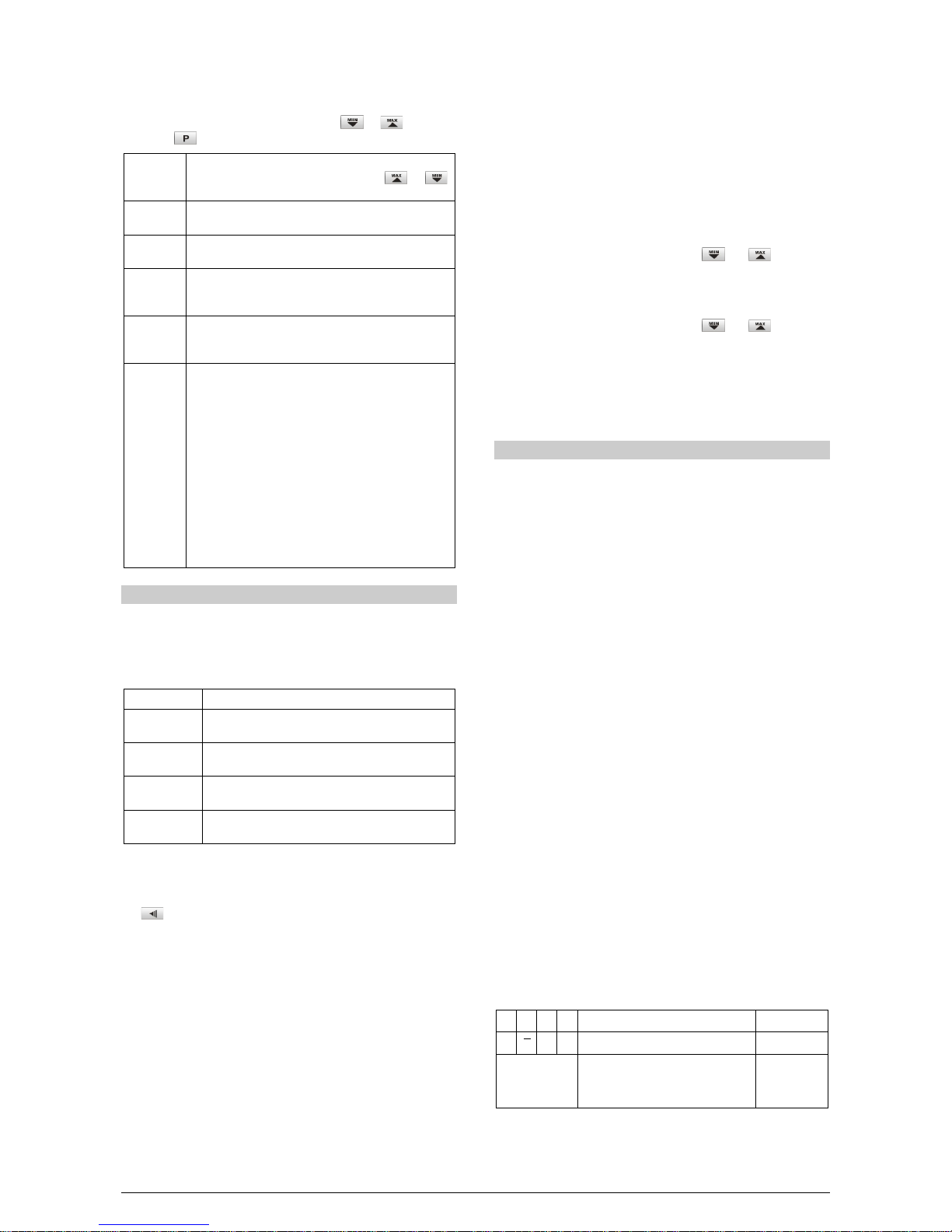
Address
Parameter
Register Description
0000 PV Read: process variable.
Write: not allowed.
Range: the minimum value is in
inlol
seted and the maximum value is in
inkil
seted an the decimal point
position depends of
dppos
.
0003 PV Read: normalized Process Variable.
Write: not allowed.
Maximum range: 0 to 62000.
0004 Display
Value Read: current display value.
Write: current display value.
Maximum range: -31000 to 31000.
The range depends of the showed
display.
SPECIFICATIONS
DIMENSIONS:.........................................48 x 96 x 92 mm (1/16 DIN).
....................................................................Approximate weight: 250 g
PANEL CUT-OUT:....................................45 x 93 mm (+0.5 -0.0 mm)
POWER:......................................100 to 240 Vac/dc ±10 %, 50/60 Hz
Optional 24V:.................... 12 to 24 Vdc / 24 Vac (-10 % / +20 %)
Max. Consumption:............................................................ 7.5 VA
ENVIRONMENTAL CONDITIONS:
Operating temperature:.................................................. 5 to 50 ºC
Maximum RH:......................................................... 80 % up to 30 ºC.
......................For temperatures above 30 ºC, decrease 3 % per ºC.
Panel protection:............................................IP65, for indoor use;
.......................................Installation category II, pollution degree 2;
altitude < 2000 m
INPUT....................Keyboard selection of input type (refer to Table 1)
Internal resolution:................................................128000 levels
Display resolution:
Temperature: ......................................................................1 / 0.1
Other measures..............................1 / 0.1 / 0.01 / 0.001 / 0.0001
Input sample rate:.............................5 per second for Pt100 and T/C
.................15 per second to 0-50 mV, 4-20 mA, 0-5 V and 0-10 V
Accuracy: ........Thermocouples J, K, T, N: 0.25 % of span ±1 ºC
...........................Thermocouple E, R, S, B: 0.25 % of span ±3 ºC
......................................................................Pt100: 0.2 % of span
..............................................................mA, mV, V: 0.2 % of span
Input impedance:..........................................................................
...............................0-50 mV, Pt100 and thermocouples: >10 MΩ
.....................................................................0-5 V, 0-10 V: >1 MΩ
.................................0-20 mA, 4-20 mA: 15 Ω(+2 Vdc @ 20 mA)
Pt100 measurement:...............DIN 43760 standard (α=0.00385)
Excitation current:.................................0.750 mA. 3-wire circuit,
cable resistance compensation
ANALOG OUTPUT:........................0-20 mA or 4-20 mA, 500 Ωmax.
..............................................................................4000 levels, Isolated
RELAY OUTPUT:..................................................................................
........................ALM1, ALM2: SPDT 3 A / 240 Vac (3 A / 30 Vdc Res.)
..............ALM3, ALM4: SPST-NO: 1.5 A / 250 Vac (3 A / 30 Vdc Res.)
EMC:................................EN 61326-1:1997 and EN 61326-1/A1:1998
SAFETY: ..........................EN61010-1:1993 and EN61010-1/A2:1995
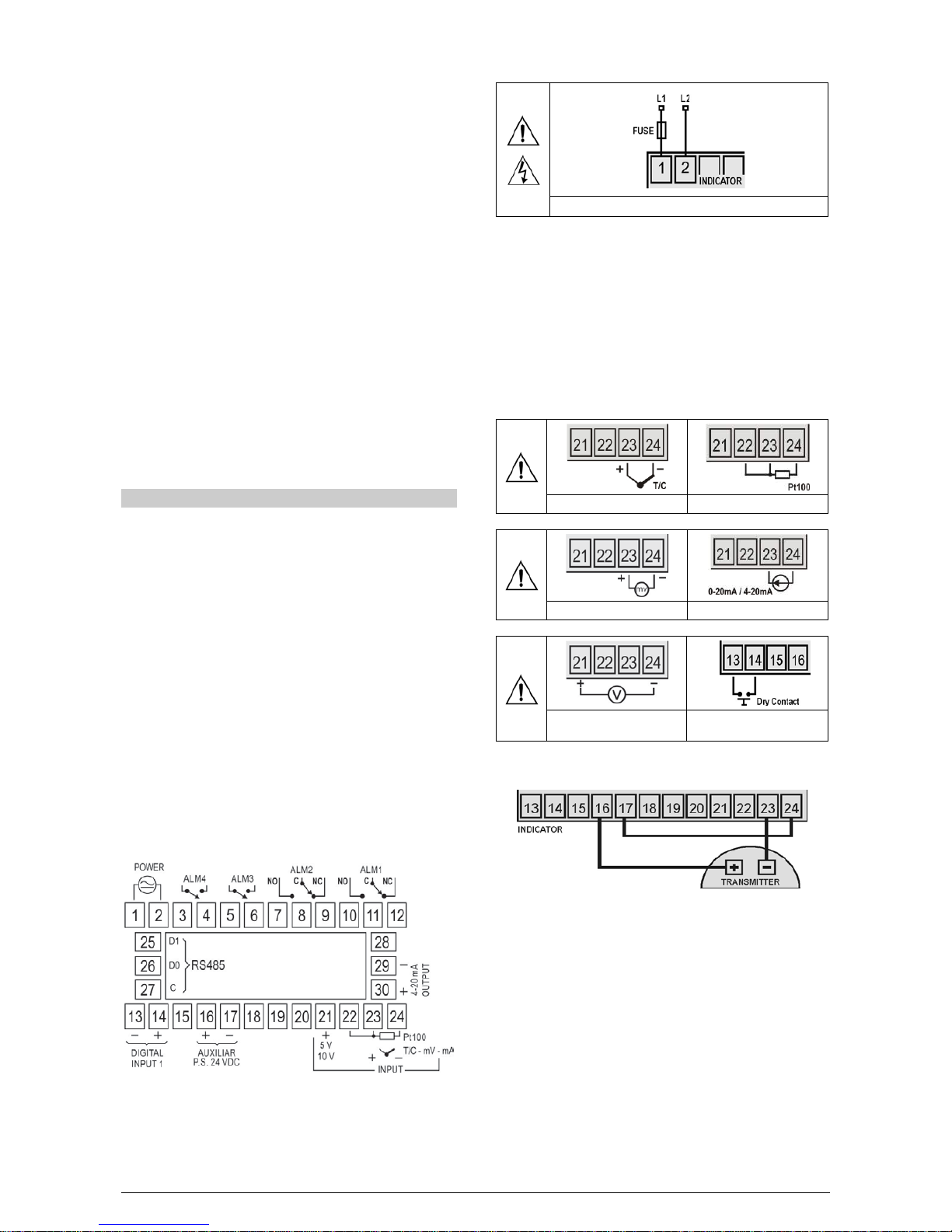
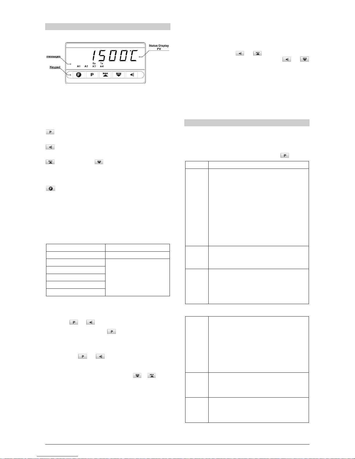
SPECIFIC CONNECTIONS FOR TYPE FORK TERMINALS OF 6.3
MM;
CASE: Polycarbonate UL94 V-2; Caixa: ABS+PC UL94 V-0;
START UP: 3 seconds after power up.
CERTIFICATIONS: .......................................CE / UL (FILE: E300526)
ORDERING INFORMATION:
N1500 - 4R - RT - 485 - 24V
A B C D E
A: Series model: N1500
B: Relays outputs: blank (2 relays); 4R (4 relays)
C: Analog output: RT –(Retransmission of the input
signal) orBlank
D: Digital Communication: 485 –(RS485, ModBus protocol) or
Black
E: Voltage rating: blank (100-240 Vac/dc); 24V (12 to 24
Vdc / 24 Vac)
WARRANTY
Warranty conditions are available on our web site
www.novusautomation.com/warranty.
Table of contents
Other Novus Touch Panel manuals
Popular Touch Panel manuals by other brands

PXM
PXM PANEL DOTYKOWY manual

Avalue Technology
Avalue Technology RPC-0801-910 Quick reference guide

Beijer Electronics
Beijer Electronics X2 control 15-B2 installation manual

Grossenbacher Systeme
Grossenbacher Systeme WebPanel WP-284-10P-000 operating instructions

VarTech Systems
VarTech Systems VTPC104P user guide

Crestron
Crestron Isys i/O TPMC-15-CH Operation guide