ElevATE Semiconductor Rainier User manual

Document Title:
Document No:
Revision No:
Release Date:
EVM Guide: Rainier EVM3.1 with Testbench1.2
15-50294-14
C
02/15/23
Copyright ©Elevate Semiconductor Corporation 2023 Page 1 of 29
EVM Guide: Rainier EVM3.1 with Testbench1.2
Rev C: February 15, 2023
This document contains information on a product under development and the material is subject to
change.

Document Title:
Document No:
Revision No:
Release Date:
EVM Guide: Rainier EVM3.1 with Testbench1.2
15-50294-14
C
02/15/23
Copyright ©Elevate Semiconductor Corporation 2023 Page 2 of 29
Document Revision History
Revision
Date
Description
A
01/04/2023
EVM3 with Testbench1.0 release
B
01/13/2023
EVM3 with Testbench1.1 release
C
02/15/2023
EVM3 with Testbench1.2 release
Table of Contents
1INTRODUCTION .......................................................................................................................................... 4
1.1 Unpacking - EVM Contents ...................................................................................................................................................4
1.2 Recommended Test and Measurement Setup.....................................................................................................................4
1.2.1 Power Supply.................................................................................................................................................................4
1.2.2 PC Controller..................................................................................................................................................................4
1.2.3 Lab Equipment ..............................................................................................................................................................5
1.3 Software Installation.............................................................................................................................................................6
2HARDWARE................................................................................................................................................ 8
2.1 Micro-USB..............................................................................................................................................................................9
2.2 Power Supply Options ...........................................................................................................................................................9
2.3 Single-Ended or Differential Mode Hardware Setup .............................................................................................................9
2.4 Caution ................................................................................................................................................................................10
3GUI OVERVIEW .........................................................................................................................................11
4CONNECTING THE EVM AND POWERING THE RAINIER DEVICE ............................................................. 13
4.1 Connecting to the EVM........................................................................................................................................................13
4.2 Powering Up the Rainier Device..........................................................................................................................................14
4.3 Powering Down the Rainier Device.....................................................................................................................................15
5MAIN GUI TABS ........................................................................................................................................ 16
5.1 Register Maps .....................................................................................................................................................................16
5.1.1 Manually Selecting Registers ......................................................................................................................................17
5.1.2 Load and Save Register Setups...................................................................................................................................18
5.2 Power Controls ....................................................................................................................................................................20
5.3 ADC/Relays.........................................................................................................................................................................21
5.3.1 Measure Analog Mux (Diagnostic Mux) .......................................................................................................................21
5.3.2 EVM Relays ..................................................................................................................................................................21
5.4 MON.....................................................................................................................................................................................22
5.4.1 MON/Diag GUI .............................................................................................................................................................22
5.4.2 Measure Die Temperature...........................................................................................................................................22

Document Title:
Document No:
Revision No:
Release Date:
EVM Guide: Rainier EVM3.1 with Testbench1.2
15-50294-14
C
02/15/23
Copyright ©Elevate Semiconductor Corporation 2023 Page 3 of 29
5.5 Fuses....................................................................................................................................................................................26
5.5.1 Serial Number Fuses.....................................................................................................................................................26
5.5.2 Channel Calibration Fuses ............................................................................................................................................26
5.5.3 Individual Fuse Bits.......................................................................................................................................................26
6RAINIER EVM LOADBOARD DESCRIPTION.............................................................................................. 27
6.1 EVM Loadboard ...................................................................................................................................................................27
7BASIC SETUPS.......................................................................................................................................... 28
7.1 Driver/Comparator Modes..................................................................................................................................................28
7.2 PMU.....................................................................................................................................................................................28
Table of Figures
FIGURE 1: RAINIER EVM SETUP...........................................................................................................................................................5
FIGURE 2: USB FILES IN TESTBENCH FOLDER.......................................................................................................................................6
FIGURE 3: DESKTOP WITH TESTBENCH SHORTCUT..............................................................................................................................6
FIGURE 4: TESTBENCH APPLICATION ICON..........................................................................................................................................7
FIGURE 5: OVERVIEW OF RAINIER EVALUATION BOARD .....................................................................................................................8
FIGURE 6: GUI DISPLAY OF EVM OPERATION MODE- SINGLE-ENDED MODE......................................................................................10
FIGURE 7: GUI OVERVIEW ................................................................................................................................................................11
FIGURE 8: DEVICE MANAGER WINDOW............................................................................................................................................13
FIGURE 9: EVM STATUS OVERVIEW ..................................................................................................................................................14
FIGURE 10: POWER AND CONNECTION BLOCK OVERVIEW................................................................................................................15
FIGURE 11: REGISTER MAPS TAB OVERVIEW.....................................................................................................................................16
FIGURE 12: REGISTERS TAB, CHANNEL 3 EXAMPLE............................................................................................................................17
FIGURE 13: SAVE REGISTERS WINDOW.............................................................................................................................................18
FIGURE 14: NOTICE OF SCRIPT LOAD SUCCESS..................................................................................................................................19
FIGURE 15: POWER CONTROLS TAB OVERVIEW................................................................................................................................20
FIGURE 16: ADC/RELAYS TAB OVERVIEW..........................................................................................................................................21
FIGURE 17: MON TAB OVERVIEW.....................................................................................................................................................22
FIGURE 18: SEL_MON SET TO TJ_P AND TJ_N FOR TEMPERATURE MEASUREMENT...........................................................................23
FIGURE 19: FUSES TAB OVERVIEW....................................................................................................................................................26
FIGURE 20: EVM HARDWARE ...........................................................................................................................................................27
FIGURE 21: REAL TIME DATA SETUP .................................................................................................................................................28
FIGURE 22: PMU SETUP....................................................................................................................................................................29
Table of Tables
TABLE 1: RAINIER EVM CONTENTS......................................................................................................................................................4
TABLE 2: POWER SUPPLY REQUIREMENTS..........................................................................................................................................4
TABLE 3: RAINIER PMU - SMU CONFIGURATION...............................................................................................................................28

Document Title:
Document No:
Revision No:
Release Date:
EVM Guide: Rainier EVM3.1 with Testbench1.2
15-50294-14
C
02/15/23
Copyright ©Elevate Semiconductor Corporation 2023 Page 4 of 29
1Introduction
Congratulations on your purchase of an Elevate Semiconductor evaluation system. You will find that it
serves as an invaluable development platform to help get your product to market in the shortest possible
time. The evaluation board and GUI (Graphical User Interface) allow the customer to demonstrate and
evaluate the performance and functionality.
This document provides the instructions to install, setup, and operate the EVM (Evaluation Module).
1.1 Unpacking - EVM Contents
Please check the contents of the EVM shipping carton to make sure you have received all the items listed
in Table 1. The EVM system ships ready to operate except for a PC with USB port and connections to
optional test equipment.
TABLE 1: RAINIER EVM CONTENTS
Qty
Description
1 each
Rainier EVM System (Zedboard FPGA and Rainier Loadboard)
1 each
Rainier EVM# GUI Guide(this document)
1 each
Rainier Device Guide
1 each
Rainier EVM Calibration Guide
1 each
AC Adapter Power Plug
1 each
Elevate Semiconductor User Interface Program Installation Flash Drive
1 each
Micro - USB Cable
1.2 Recommended Test and Measurement Setup
1.2.1 Power Supply
The included power adapter provides all the power needed for the evaluation system (FPGA plus Rainier
loadboard). If the power adapter becomes lost or does not work, a +12V supply can be used to optionally
provide power to the evaluation system. Table 2 provides the required power supply and current rating. The
external power supply is connected to the board using standard banana plugs (not provided).
TABLE 2: POWER SUPPLY REQUIREMENTS
Module
Supply
Current Rating
Rainier EVM/FPGA
+12V
3 A
1.2.2 PC Controller
To use the Rainier EVM User Interface Program (UIP), a PC with the following configuration is required:
•Windows 10
•USB Port (a USB cable is provided)

Document Title:
Document No:
Revision No:
Release Date:
EVM Guide: Rainier EVM3.1 with Testbench1.2
15-50294-14
C
02/15/23
Copyright ©Elevate Semiconductor Corporation 2023 Page 5 of 29
1.2.3 Lab Equipment
The below lab equipment can be used for evaluation of the Rainier product along with any other equipment
the user deems useful.
•Voltage and/or Current Source
•DMM
•Oscilloscope
•Pulse Generator
•Resistor/Capacitor Loads
Power
Supplies
PC
Optional Lab
Equipment
FMC Connector
Elevate
Semiconductor
Rainier Loadboard
Zedboard Xilinx
FPGA
FIGURE 1: RAINIER EVM SETUP

Document Title:
Document No:
Revision No:
Release Date:
EVM Guide: Rainier EVM3.1 with Testbench1.2
15-50294-14
C
02/15/23
Copyright ©Elevate Semiconductor Corporation 2023 Page 6 of 29
1.3 Software Installation
The Rainier EVM software is on the included GUI flash drive. To ensure the evaluation board is correctly
recognized when connected to the PC, the software should be installed before connecting the board to the
PC’s USB port.
First plug in the provided USB.
From the USB, run the .NET Framework application located on the flash drive to Local Disk C: It is also
available for web download at: https://dotnet.microsoft.com/en-us/download/dotnet-framework/thank-
you/net472-web-installer.
Once the .NET Framework is installed, unzip the Testbench software to Local Disk C:, create a new folder
named “Elevate”:
FIGURE 2: USB FILES IN TESTBENCH FOLDER
You may also create a shortcut on your Desktop to connect to the file location on the Local Disk drive.
FIGURE 3: DESKTOP WITH TESTBENCH SHORTCUT

Document Title:
Document No:
Revision No:
Release Date:
EVM Guide: Rainier EVM3.1 with Testbench1.2
15-50294-14
C
02/15/23
Copyright ©Elevate Semiconductor Corporation 2023 Page 7 of 29
Once unzipped to your desired location, select the Testbench Application to launch the software:
FIGURE 4: TESTBENCH APPLICATION ICON
The installation is now complete.
Document Title:
Document No:
Revision No:
Release Date:
EVM Guide: Rainier EVM3.1 with Testbench1.2
15-50294-14
C
02/15/23
Copyright ©Elevate Semiconductor Corporation 2023 Page 8 of 29
2Hardware
The Rainier EVM2 is shipped with several pre-configured states and a user interface program that allows
a customer to evaluate the Pin Electronics, PPMU (Per-Pin Parametric Measurement Unit (Force
Voltage/Current - Measure Voltage/Current), Comparators, Active Loads, and other features. See Section
5.5 for details on loadboard hookup.
Note: Any external equipment providing digital signals into the Rainier device should only be enabled after
the Rainier EVM is enabled and the Rainier device is powered on. Any external equipment should also be
disabled prior to disabling the Rainier EVM.
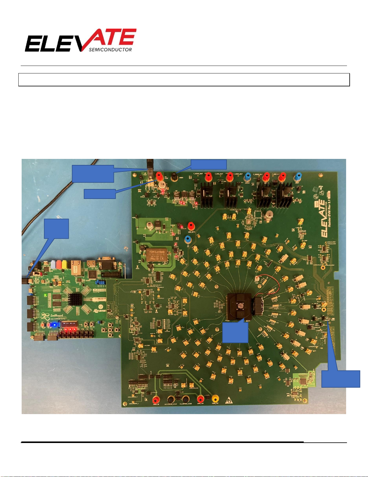
FIGURE 5: OVERVIEW OF RAINIER EVALUATION BOARD
Plug for Included
Power Adapter
Rainier
Device
With FAN
+12V (P2)
GND (GND1)
Micro
USB
(UART)
PROD0 Jumper
S.E. or Diff Mode

Document Title:
Document No:
Revision No:
Release Date:
EVM Guide: Rainier EVM3.1 with Testbench1.2
15-50294-14
C
02/15/23
Copyright ©Elevate Semiconductor Corporation 2023 Page 9 of 29
2.1 Micro-USB
Connect the included micro-USB cable from your PC to the micro-USB port on the Rainier EVM as show in
Figure 5. This micro-USB connector is labeled UART (J14) on the FPGA Zedboard. This connector is small
and can break off the Zedboard with lateral movement of the USB cable. Take caution when connecting
the cable to avoid damage to the board.
2.2 Power Supply Options
There are 2 power options for the Rainier EVM. Only 1 of the following options is required:
1. Wall power adapter (Included with Evaluation System).
a. Connect wall adapter to the 12V power barrel connecter, J8.
2. +12V External Supply.
a. Connect power supplies cables (not provided) from your power supply to the Elevate Semiconductor EVM
Rainier board’s +12V (P2) and GND (GND1) banana connectors.
2.3 Single-Ended or Differential Mode Hardware Setup
As shown above in Figure 5, the user may connect the jumper on PROD0 to VDDIO to operate the EVM in
single-ended mode or connect PROD0 to GND to operate in Differential mode.
The current board status will be displayed in the Global Block, in the DEV_REV register. This is a read only
register and cannot be written.
The user may check if the device is set up to the desired state in the Global Block, Dev_Rev register:
When the “Single_Ended_State” bit is HIGH the EVM operates in single-ended mode.
When the “Single_Ended_State” bit is LOW the EVM operates differential operation.

Document Title:
Document No:
Revision No:
Release Date:
EVM Guide: Rainier EVM3.1 with Testbench1.2
15-50294-14
C
02/15/23
Copyright ©Elevate Semiconductor Corporation 2023 Page 10 of 29
FIGURE 6: GUI DISPLAY OF EVM OPERATION MODE- SINGLE-ENDED MODE
2.4 Caution
The Rainier Socket may get hot even with the included fan running. The user should be cautious about
handling the device or socket.
Document Title:
Document No:
Revision No:
Release Date:
EVM Guide: Rainier EVM3.1 with Testbench1.2
15-50294-14
C
02/15/23
Copyright ©Elevate Semiconductor Corporation 2023 Page 11 of 29
3GUI Overview
This section is an overview of the what is contained in the Testbench GUI. Powering up the device and
details about specific pages are discussed later in this document.
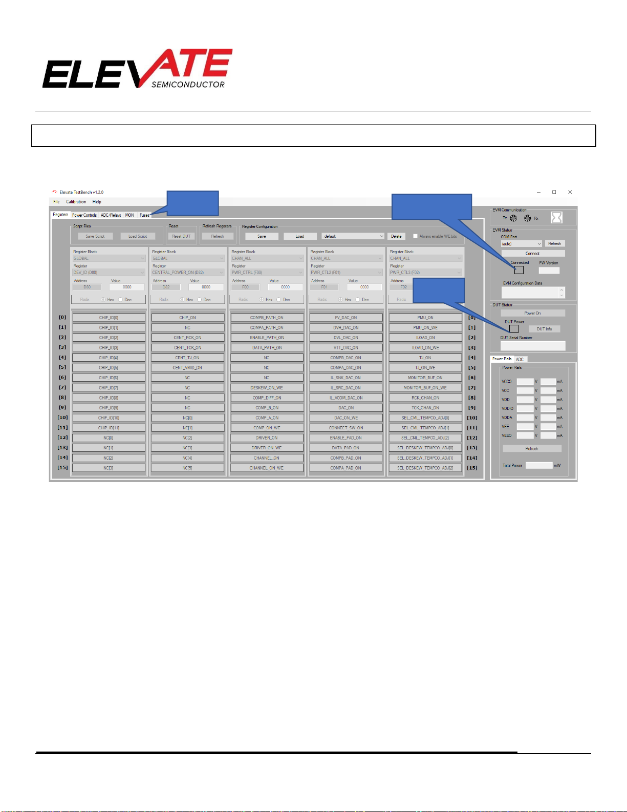
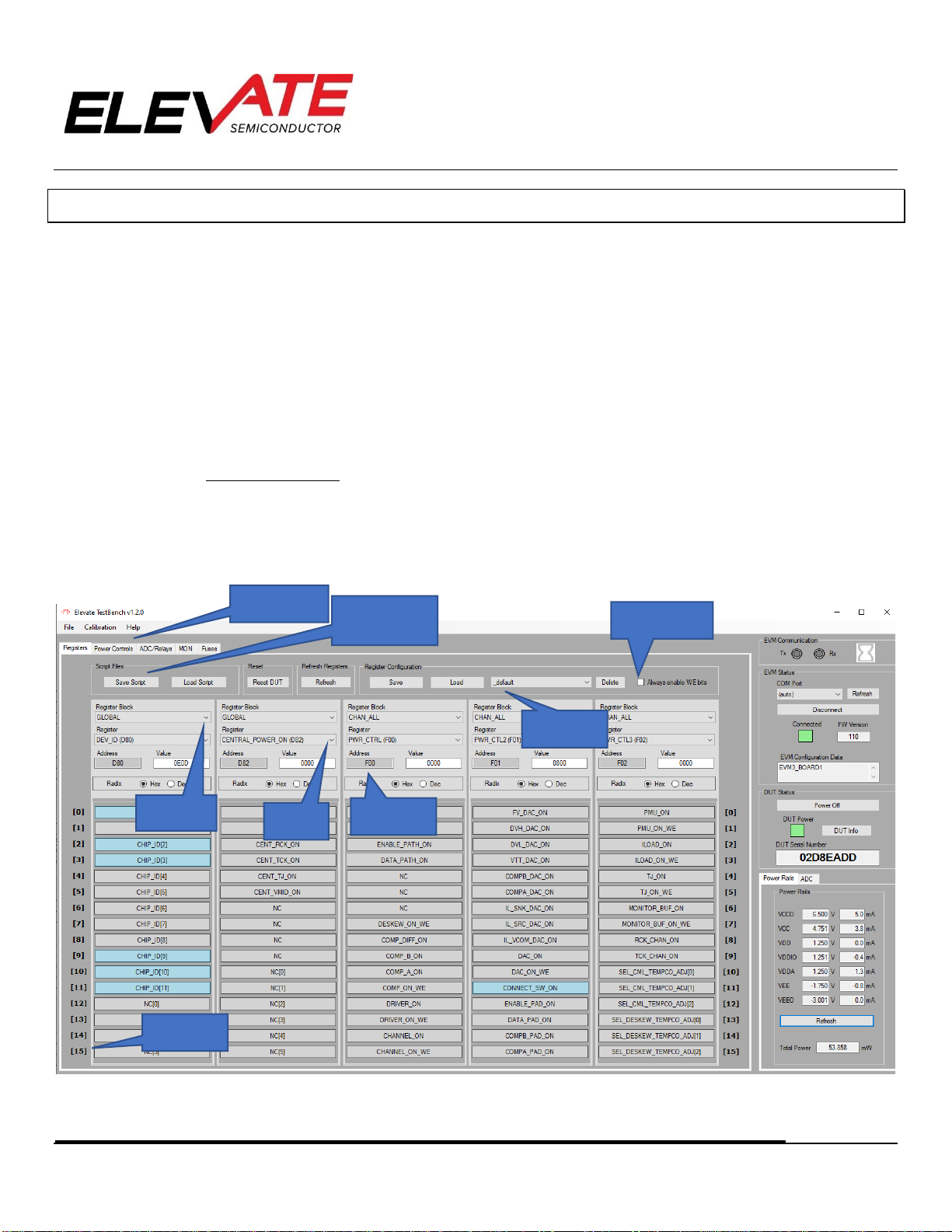
FIGURE 7: GUI OVERVIEW
1. Upon startup of the software, the EVM board is powered on, but it is not yet connected to the GUI. In the EVM
Status box, the user can connect the software to the device by either selecting which “COM” port to look at from
the drop-down menu or selecting “auto” then clicking the “Connect” button. The EVM Communication TX and RX
indicators will blink green to show the software is talking to the EVM, then the “Connected” box will turn green
once the program is successfully connected.
2. Once the GUI is connected to the EVM, the device will not be powered up as the DUT power box will be uncolored.
After powering up the Rainier device, this box will turn green. (The power up sequence is shown below in section
4).
3. The Elevate GUI software is broken up into 5 main tabs:
a. Registers: The Rainier device can be programmed using register settings versus graphical setup. There are
options to set register bits and DAC levels for individual channels or all channels. There are also options to
save and load setups from files.
b. Power Controls: Allows user to change power rails. Also contains temperature measurements for central diode
and for each channel.
c. ADC/Relays: This page has options to measure the calibration/monitor pins. There is also the feature to set
the EVM relays to route an ADC channel to the on-board passive loads (Load_Star_High SMA) circuit on the
EVM
DUT Power
Status
GUI Tabs
EVM Connection
Status

Document Title:
Document No:
Revision No:
Release Date:
EVM Guide: Rainier EVM3.1 with Testbench1.2
15-50294-14
C
02/15/23
Copyright ©Elevate Semiconductor Corporation 2023 Page 12 of 29
d. MON: Contains a GUI of the Monitor path. Users can use the drop-down menus to select the Monitor channel,
set SEL_MON to different modes, and set the Diagnostic buses for different measurements.
e. Fuses: Contains Serial Number Decoder and other fuse bits used in calibration. NOTE: ADVANDED USERS
ONLY. Use with caution, burned fuses are permanent. Cannot be undone.
4. Each of the GUI controls is a visual representation of a register in the Rainier device. Once the user moves tabs,
selects a register block etc., a register in the Rainier device will be programmed to match the corresponding GUI
input.
Document Title:
Document No:
Revision No:
Release Date:
EVM Guide: Rainier EVM3.1 with Testbench1.2
15-50294-14
C
02/15/23
Copyright ©Elevate Semiconductor Corporation 2023 Page 13 of 29
4Connecting the EVM and Powering the Rainier Device
This section is designed to show the user how to connect and power up the Rainier device.
4.1 Connecting to the EVM
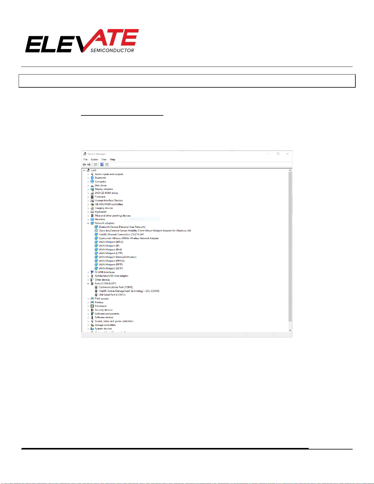
1. Users must connect the GUI to the EVM before operating the device. In the EVM Status section, use the drop-down
menu to select which COM port to connect to then click the “Connect “button.
a. Users can see what COM the EVM connects to by viewing Device Manger > Ports (COM & LPT).
FIGURE 8: DEVICE MANAGER WINDOW
b. If the EVM option is not available on the drop-down menu, try selecting the “Refresh” button or select “auto”
from the menu.
2. When the software tries to connect the EVM, the EVM Communication section will display TX and RX indicators
flashing in green to give user feedback that the software is working.
3. When the connection is successful, the “Connected” indicator box will appear green, and the “Connect” button will
now say “Disconnect” so it may now be used to sever the connection between the GUI and the EVM.
Document Title:
Document No:
Revision No:
Release Date:
EVM Guide: Rainier EVM3.1 with Testbench1.2
15-50294-14
C
02/15/23
Copyright ©Elevate Semiconductor Corporation 2023 Page 14 of 29
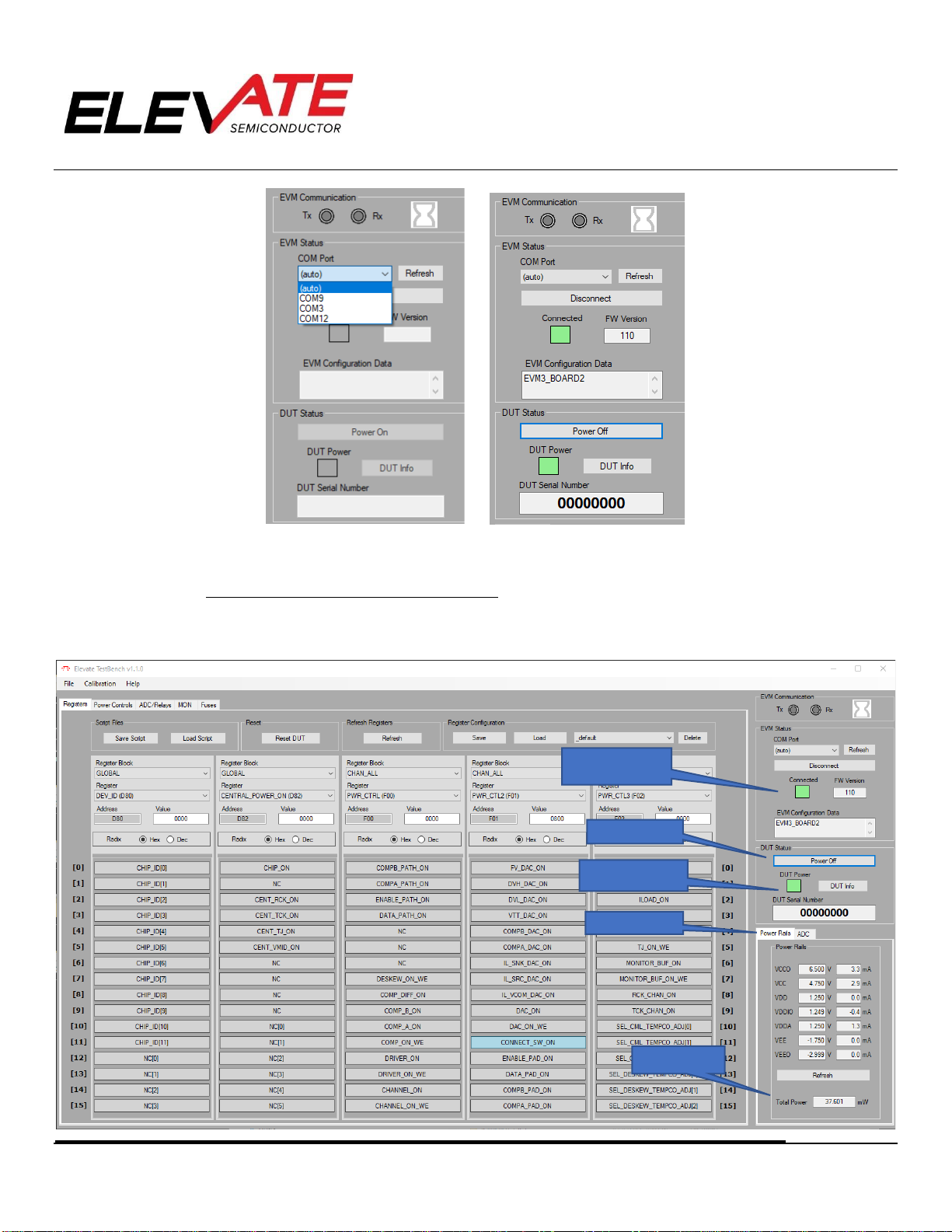
FIGURE 9: EVM STATUS OVERVIEW
4.2 Powering Up the Rainier Device
1. After connecting the EVM board and installing the Elevate GUI software as shown in the Software Installation
Section, you can power on the Rainier device.
Total Power
DUT Power Status
Power Button
Power Rails Tab
EVM Connection
Status

Document Title:
Document No:
Revision No:
Release Date:
EVM Guide: Rainier EVM3.1 with Testbench1.2
15-50294-14
C
02/15/23
Copyright ©Elevate Semiconductor Corporation 2023 Page 15 of 29
FIGURE 10: POWER AND CONNECTION BLOCK OVERVIEW
2. Powering up the Rainier device uses the “DUT status” section of the Registers tab of the Rainier GUI.
3. Powering up Rainier Device:
a. Select the Power ON button.
b. Wait for the TX and RX indicators to finish flashing.
c. When the device is successfully powered on, the DUT Power indicator will turn green, the Device SN will
appear under Device ID. The “Power On” button will change to read “Power Off” and now may be used to turn
the device off when finished.
d. The measured voltage, current, and power for each supply are displayed in the Power Rails section.
e. At this point, the device is now in a powered-up state and ready to start characterizing or testing. Note that the
GUI automatically obeys the power up sequence guidelines.
4.3 Powering Down the Rainier Device
To power down the Rainier device, left click the “Power Off” button. The “DUT Power” indicator will change from green to no
color. This will indicate Rainier is no longer powered up. Again, via the GUI, the order will be correct.
Document Title:
Document No:
Revision No:
Release Date:
EVM Guide: Rainier EVM3.1 with Testbench1.2
15-50294-14
C
02/15/23
Copyright ©Elevate Semiconductor Corporation 2023 Page 16 of 29
5Main GUI Tabs
Each of the major GUI tab sections will be discussed below. The are 4 major sections of the Graphical User
Interface as stated in the GUI overview section. Each will be discussed or shown below:
1. Registers
2. Power Controls
3. ADC/Relays
4. MON
5. Fuses
5.1 Register Maps
The Rainier device can be programmed using register settings. There are options to set register bits and
DAC levels for individual channels or all channels.
There is also the option to save register setups and load register setups from files. These are used to set
and save the Rainier device in a known configuration.
FIGURE 11: REGISTER MAPS TAB OVERVIEW
Block
Selection
Register
Selection
Register
Address
Save Register
Configuration
Save Register
Values to script
Registers Tabs
Bit Address
WE bits enabled in
VALUE
Document Title:
Document No:
Revision No:
Release Date:
EVM Guide: Rainier EVM3.1 with Testbench1.2
15-50294-14
C
02/15/23
Copyright ©Elevate Semiconductor Corporation 2023 Page 17 of 29
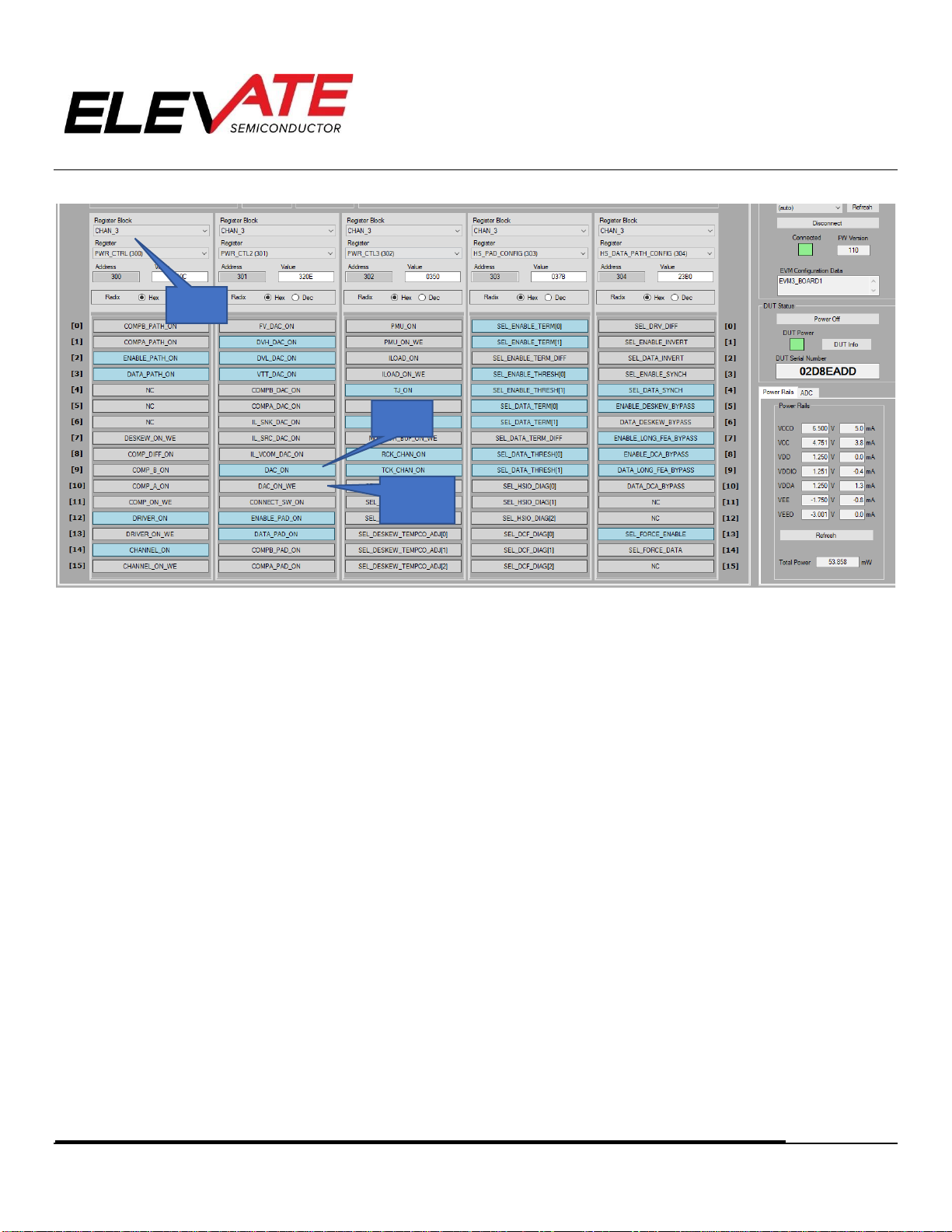
FIGURE 12: REGISTERS TAB, CHANNEL 3 EXAMPLE
5.1.1 Manually Selecting Registers
1. The Registers tab for the Rainier Device is broken into 3 sections. Blocks, Registers, and Bits. Blocks are only
terms used in the GUI and are not part of the device. Each of these concepts is explained below:
a. Blocks: Blocks are just a term for a grouping of registers that are related in the Rainier device. Each of the
blocks can have many registers or just a few. Each block of registers controls a separate section of the device.
All blocks related to the Rainier are shown in the “Block Selection” pulldown menu.
I. Per Chip Blocks: This selection affects the central section of the device. The GLOBAL section of the
register map is per-chip selection and is shown above. The GLOBAL block selection is a section of the
register map that is central to the device and is not specific to any channel.
II. Per Channel Blocks: These block selections will only affect 1 channel. For example, CHAN_0 will only
affect channel 0. The Per-channel selections will be indicated by: “Block Name” + “_” + “channel
number”.
III. All channel Blocks: Selecting this block will affect all channels when a register is written. For example,
CHAN_ALL: The All-channel selections will be indicated by: “Block Name” + “_” + “ALL”.
b. Registers: The registers in Rainier are all 16-bit registers. As an example, all the Registers Blocks are set to
CHAN_3 and the first five registers are shown in Figure 12.
I. Register Name: This matches the register map name in the datasheet. PWR_CTRL in the above example.
II. Register Address: The address of the register is below the Register name.
III. Address 300 in the above example. The first number in the address matches the channel number (channel
3). The second 2 numbers match the REG ADR in the datasheet (address 00).
c. Bits: Each Block Selection is further broken into 16 Bits. The 16 bits of each block can be selected by clicking
on the desired bit button.
Register
Name
Bit
Name
Write
Enable
(“WE”) bit

Document Title:
Document No:
Revision No:
Release Date:
EVM Guide: Rainier EVM3.1 with Testbench1.2
15-50294-14
C
02/15/23
Copyright ©Elevate Semiconductor Corporation 2023 Page 18 of 29
I. If a register bit is written as a ‘0’, the register bit is gray. If the register bit is a ‘1’, the register is blue.
II. The user should press the “Update” button after writing registers to make sure the correct registers
were written.
III. There are bits within certain registers that can be written independently without affecting the other bit
fields in that register. For these registers each independent bit field has a WE (write enable) bit defined
that must be set to "1" for those bits to be affected by a write.
i. This GUI considers the WE bit as ‘1’ by default. When saving a script, the WE bit is by default saved as a
“1” so when the script loads all desired bits field are set correctly.
5.1.2 Load and Save Register Setups
The “Save Script” and “Load Script” buttons can be used to save and load register settings. These 2
selections are discussed below:
FIGURE 13: SAVE REGISTERS WINDOW
1. “Save Script” button:
a. “All Registers” checkbox: Will save every register and bit value in sequential order by register address.
b. “Delta from POR” checkbox: Will only save registers that have values different than the power on reset
register values.
c. “Specific register banks”: Allows the user to select desired registers to be saved.
d. “All”: Selects all register checkbox selections
e. “None”: Clears all register checkbox selections
2. “Load Script” button: Runs the entire setup file selected and writes all the registers at one time. Note that saving
off an entire register map can take about 1 minute. If the Tx/Rx lights are green, the save is in progress.

Document Title:
Document No:
Revision No:
Release Date:
EVM Guide: Rainier EVM3.1 with Testbench1.2
15-50294-14
C
02/15/23
Copyright ©Elevate Semiconductor Corporation 2023 Page 19 of 29
FIGURE 14: NOTICE OF SCRIPT LOAD SUCCESS

Document Title:
Document No:
Revision No:
Release Date:
EVM Guide: Rainier EVM3.1 with Testbench1.2
15-50294-14
C
02/15/23
Copyright ©Elevate Semiconductor Corporation 2023 Page 20 of 29
5.2 Power Controls
Each of the supplies is pre-programmed with the nominal voltage value for each of the supplies. After the
device is powered-up, the supply values can be changed by entering a new value in the “Power Rail Control”
dialog box of each individual supply located in the “Power Controls” tab.
FIGURE 15: POWER CONTROLS TAB OVERVIEW
Enter a new value and press the Enter key. If an invalid number is written to one of the Set Voltage dialog
boxes, the dialog box will flash red and set the closest valid value.
The user can go back to this page as needed and enter new voltage settings into the set voltage dialog
boxes to change the power supplies. The Power Rails display in the sidebar will update with the new
measured voltages/currents after hitting the “Refresh” button.
The user can measure die temperature after calibrating the Monitor Buffer. See Section 5.4.2 Measure Die
Temperature and Rainier EVM Calibration Guide for more details.
NOTE: DO NOT MEASURE TEMPERATURE BEFORE CALIBRATING MONITOR BUS
Table of contents
Other ElevATE Semiconductor Motherboard manuals


