ElevATE Semiconductor Vesuvius User manual
Vesuvius EVM Getting Started Rev A2: 06/26/17
Copyright Elevate Semiconductor Corporation 2016 Page 1 of 30
Vesuvius EVM Getting Started
Rev A2: 06/26/17
This document contains information on a product under development and the material is
subject to change.

Vesuvius EVM Getting Started Rev A2: 06/26/17
Copyright Elevate Semiconductor Corporation 2016 Page 2 of 30
Table of Contents
1Introduction ..........................................................................................................................................................4
1.1Unpacking - Vesuvius EVM Contents ........................................................................................................ 4
1.2Recommended Test and Measurement Setup ........................................................................................... 5
1.2.1Power Supply ......................................................................................................................................... 5
1.2.2PC Controller ......................................................................................................................................... 5
1.2.3DMM or Source Measurement Unit ...................................................................................................... 5
1.3Software Installation ................................................................................................................................... 6
1.3.1Vesuvius EVM UIP Installation ............................................................................................................ 6
1.3.2USB Device Driver Installation ............................................................................................................. 6
1.3.3Reboot Machine ................................................................................................................................... 12
1.3.4Launching the Elevate Semiconductor Program .................................................................................. 1 2
1.3.5Software Un-Installation ...................................................................................................................... 12
2Getting Started ....................................................................................................................................................13
2.1Caution ....................................................................................................................................................... 13
2.2Quick Start Instructions ............................................................................................................................ 13
2.2.1Default Power Supply Option .............................................................................................................. 13
2.3Default Configuration Setup Options ...................................................................................................... 15
2.3.1Remote Kelvin Sense ........................................................................................................................... 15
2.3.2FV/MI Configuration ........................................................................................................................... 16
2.3.3FI/MV Configuration ........................................................................................................................... 17
2.3.4Channel#0 and Channel#1 Ganging (Merging) Configuration ............................................................ 18
2.3.5All channels in Ganged (Merging) Configuration ............................................................................... 1 9
2.4Motherboard Jumper and SMA Definition ............................................................................................. 20
2.5Vesuvius Loadboard Jumper Definitions ................................................................................................ 21
2.6Vesuvius EVM Menu and Dialog Boxes .................................................................................................. 22
3Vesuvius EVM Loadboard Detailed Description ...............................................................................................27
3.1Vesuvius EVM Loadboard Controller ..................................................................................................... 29
4Document Revision History................................................................................................................................30

Vesuvius EVM Getting Started Rev A2: 06/26/17
Copyright Elevate Semiconductor Corporation 2016 Page 3 of 30
List of Figures
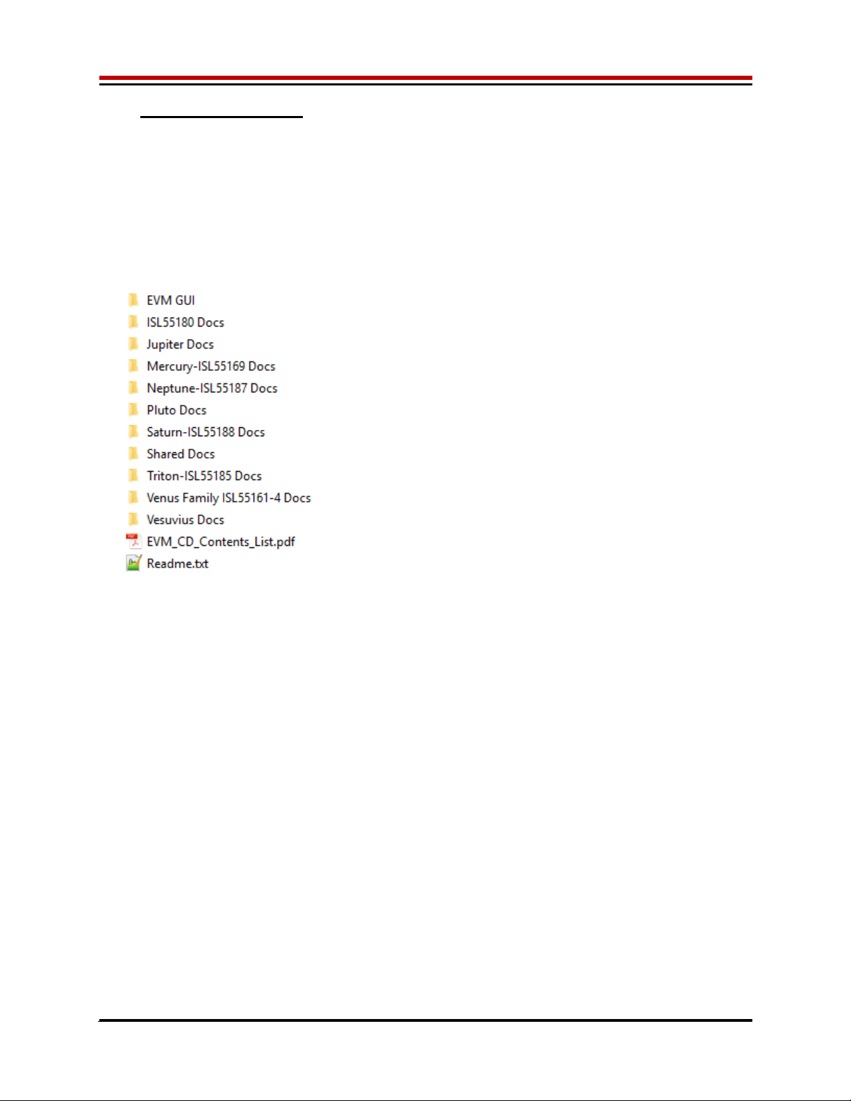
Figure 1: Installation Directory Structure ...................................................................................................... 6
Figure 2: Expected Current Readings ........................................................................................................ 14
Figure 3: Vesuvius EVM FV/MI Simplified Block Diagram ......................................................................... 16
Figure 4: Vesuvius EVM FI/MV Simplified Block Diagram ......................................................................... 17
Figure 5: Vesuvius EVM Ganging Configuration Simplified Block Diagram .............................................. 18
Figure 6: Vesuvius EVM All Channels Ganging Configuration Simplified Block Diagram ......................... 19
Figure 7: Device Configuration Menu Options ............................................................................................ 22
Figure 8: Vesuvius Configuration Dialog Box ............................................................................................ 23
Figure 9: Vesuvius DC Levels Dialog Box ................................................................................................. 24
Figure 10: Vesuvius DAC Configuration Dialog Box .................................................................................. 25
Figure 11: Vesuvius Central Register Dialog Box ...................................................................................... 26
Figure 12: Vesuvius EVM Detailed Block Diagram .................................................................................... 27
Figure 13: Vesuvius Slave Detailed Block Diagram .................................................................................. 28
Figure 14: Controller Section Detailed Block Diagram .............................................................................. 29
List of Tables
Table 1: Vesuvius EVM Contents ................................................................................................................. 4
Table 2: Power Supply Requirements ......................................................................................................... 5
Table 3: Vesuvius Default Configuration Options ...................................................................................... 15
Table 4: Motherboard SMA and Jumper Definitions (Vesuvius Input Signals) .......................................... 20
Table 5: Motherboard SMA Definitions (Vesuvius Output Signals) ........................................................... 20
Table 6: Vesuvius Loadboard Jumper Definitions ..................................................................................... 21

Vesuvius EVM Getting Started Rev A2: 06/26/17
Copyright Elevate Semiconductor Corporation 2016 Page 4 of 30
1 Introduction
Congratulations on your purchase of an Elevate Semiconductor Vesuvius evaluation system. You will find
that it serves as an invaluable development platform to help get your product to market in the shortest
possible time. The Vesuvius and Graphical User Interface (GUI) allow the customer to demonstrate and
evaluate the Vesuvius performance and functionality.
This document provides the instructions to install, setup, and operate the Vesuvius EVM. Refer to the
Elevate Semiconductor EVM User’s Guide for a detailed description of the EVM system.
1.1 Unpacking - Vesuvius EVM Contents
Please check the contents of the Vesuvius EVM shipping carton to make sure you have received all of
the items listed in Table 1. The system is already configured for the best setup, except for connections to
the power supply, PC controller, and test equipment.
Table 1: Vesuvius EVM Contents
Qt
y
Description
1 ea. Vesuvius EVM System (3 boards: Motherboard, FVMI Board, Vesuvius
Loadboard
)
1 ea. Vesuvius EVM Gettin
g
Started
(
this document
)
1 ea. EVM Contents Lis
t
1 ea. Elevate Semiconductor User Interface Pro
g
ram Installation Flash Drive
1 ea. USB A/B Cable
Vesuvius EVM Getting Started Rev A2: 06/26/17
Copyright Elevate Semiconductor Corporation 2016 Page 5 of 30
1.2 Recommended Test and Measurement Setup
1.2.1 Power Supply
Table 2 provides the required power supplies and current rating. The power supplies are connected
using standard banana plugs. The customer needs to provide the power supply cables and supplies.
It is recommended to use a triple supply to control the EVM supplies. This allows the 3 EVM supplies to
be turned on at the same time. However, if this is not feasible, then the supplies should be enabled in the
following sequence. Power down should be performed in the reverse order.
1. +20V
2. -15V
3. +5V
The Vesuvius VCCO and VEE are gated using an Opto-FET switch on the loadboard so it is safe to set
and enable the Vesuvius supplies before powering up the EVM and running the software.
Table 2: Power Supply Requirements
Module Suppl
y
Current Ratin
g
Motherboard +20V 0.5
A
Motherboard +5V (1) 0.5
A
Motherboard -15V 0.5
A
Vesuvius VCCO +5V (2, 3) 5.0
A
(4)
Vesuvius VEE -3V (2, 3) 5.0
A
(4)
Notes:
1) The EVM +5V could also be used as the Vesuvius VCCO
2) Once the EVM operation is verified, the customer can adjust the VCCO, VEE supplies
3) Make sure the external supplies do not violate the ABS max section on the datasheet.
4) The VCCO and VEE current 4A requirements are required if all 8 channels are operating at
maximum current load. If using a sub-set of channels then a smaller (i.e. 1 Amp) supply could be
adequate. The program does not have the ability to measure the VCCO and VEE currents
1.2.2 PC Controller
To use the Vesuvius EVM User Interface Program (UIP), a PC with the following configuration is required:
Windows 2007, Windows 2008, Windows 2010
USB Port (a USB cable is provided)
1.2.3 DMM or Source Measurement Unit
Voltage and/or Current Meter
Voltage and/or Current Source
Vesuvius EVM Getting Started Rev A2: 06/26/17
Copyright Elevate Semiconductor Corporation 2016 Page 6 of 30
1.3 Software Installation
There are 2 steps to install the Vesuvius EVM demonstration program.
1. Install the Vesuvius EVM UIP from the Flash Drive.
2. Install the USB driver.
Figure 1 illustrates the default directory structure. The user may change the <root dir> during the
installation.
Figure 1: Installation Directory Structure
<Root Dir>:\ElevATE Semi
1.3.1 Vesuvius EVM UIP Installation
To install the Vesuvius EVM software package, run the SETUP program on the distribution Flash Drive
and follow the prompts. The ElevATE.exe executable will be installed in the EVM GUI sub-directory. In
addition, a short cut will be installed onto the desktop and in the Start->Programs folder. The
Start->Programs folder also contains links to the different EVM User’s Guide, and documentation
folders.
1.3.2 USB Device Driver Installation
Follow section 1.3.2.1 for installation instructions on the Windows 10/8 operating systems, section 1.3.2.2
for instructions for Windows 7, or section 1.3.2.3 for Windows XP
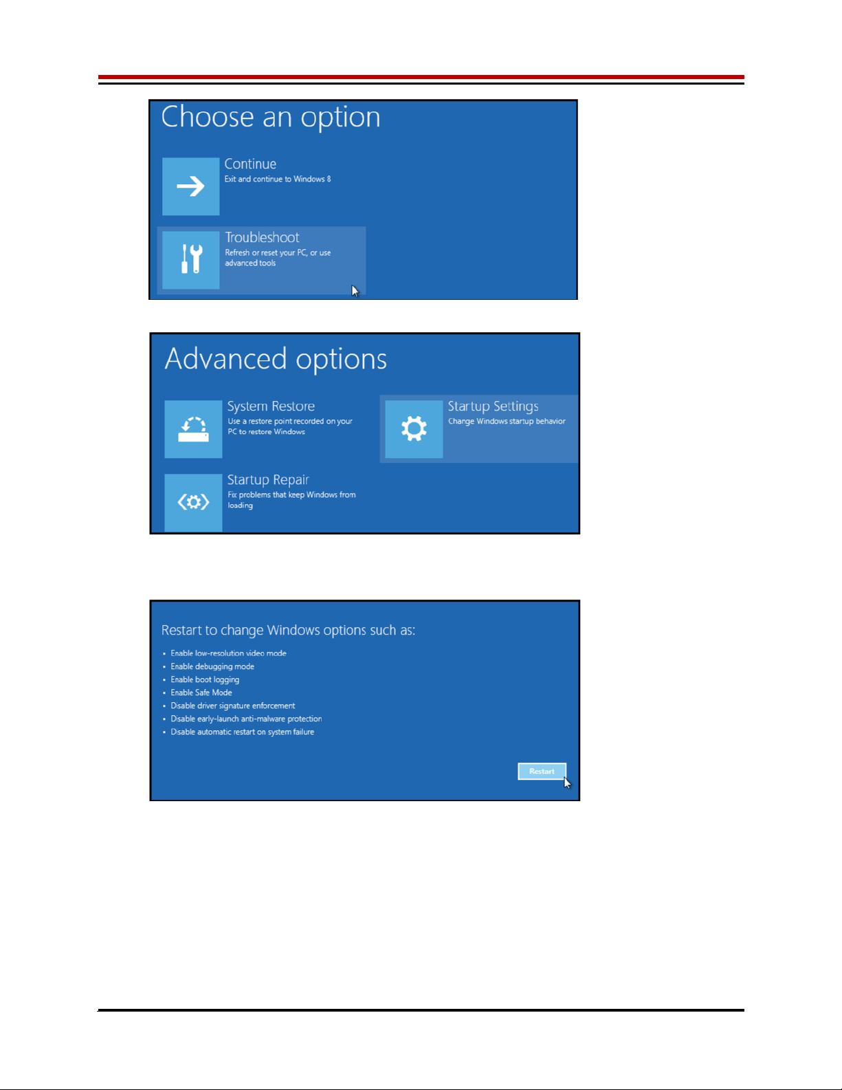
1.3.2.1 Window 10/8
To install the USB driver on Windows 10/8, the Driver Signature Verification needs to be disabled.
This is accomplished using the following method.
1.3.2.1.1 Enter the Troubleshoot menu. Click “Restart” from the power options menu and hold
down the “Shift” key at the same time. Once the computer has rebooted, you will be
able to choose the Troubleshoot option.
Vesuvius EVM Getting Started Rev A2: 06/26/17
Copyright Elevate Semiconductor Corporation 2016 Page 7 of 30
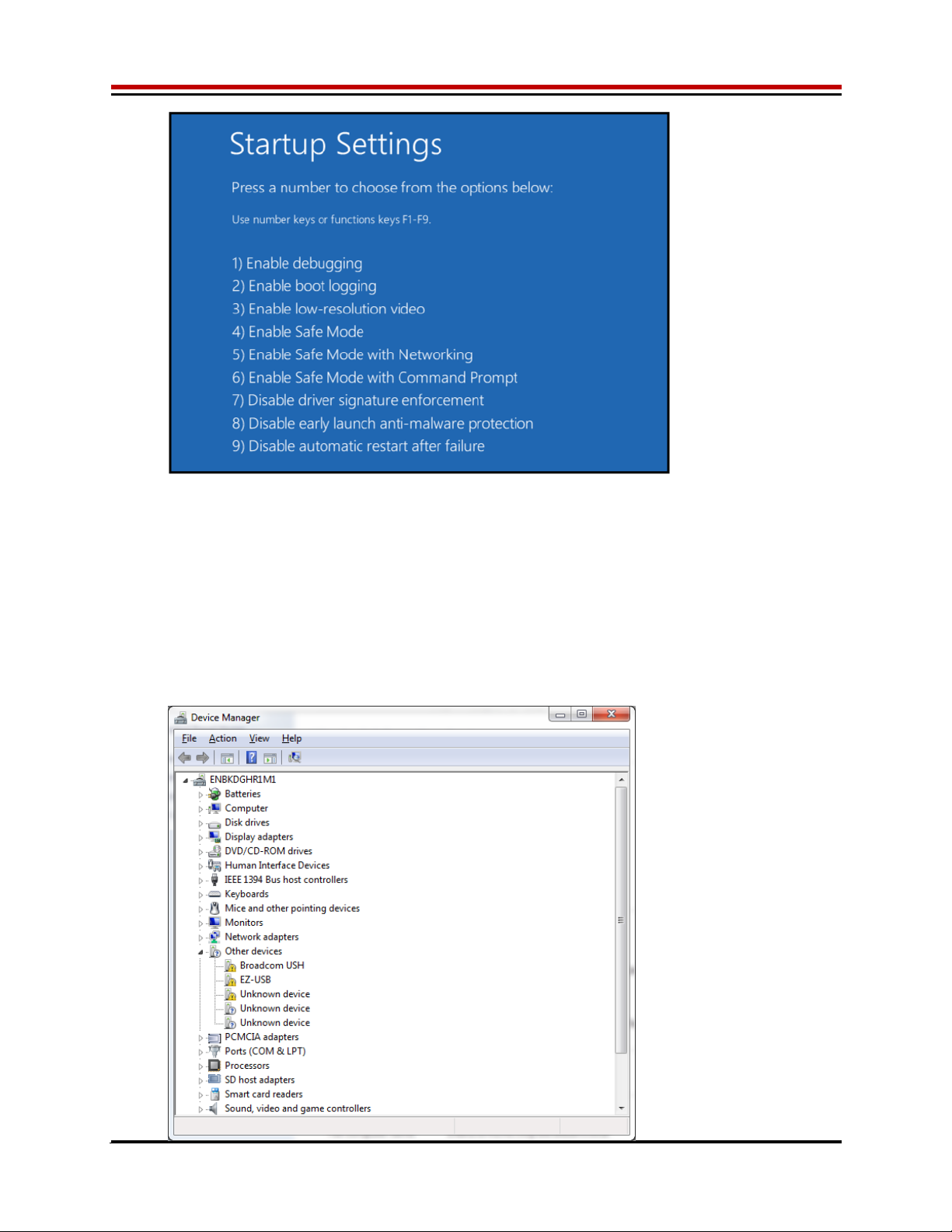
1.3.2.1.2 Select “Advanced options” and “Startup Settings”.
1.3.2.1.3 You need to restart your computer one last time to modify boot time configuration
settings.
1.3.2.1.4 You will be given a list of startup settings, including “Disable driver signature
enforcement”. To choose the setting, you need to press the “F7” key. This will disable
the driver signature enforcement until the computer is rebooted.
Vesuvius EVM Getting Started Rev A2: 06/26/17
Copyright Elevate Semiconductor Corporation 2016 Page 8 of 30
1.3.2.1.5 Continue with section 1.3.2.2 to finish installation of USB driver except choose the
windows 10 or windows 8 option.
1.3.2.2 Windows 7
To install the USB device driver on a Windows 7 system, connect the USB port using the included
USB A/B cable. The USB port does not need any external power or need to be connected to any
other board for the device driver installation.
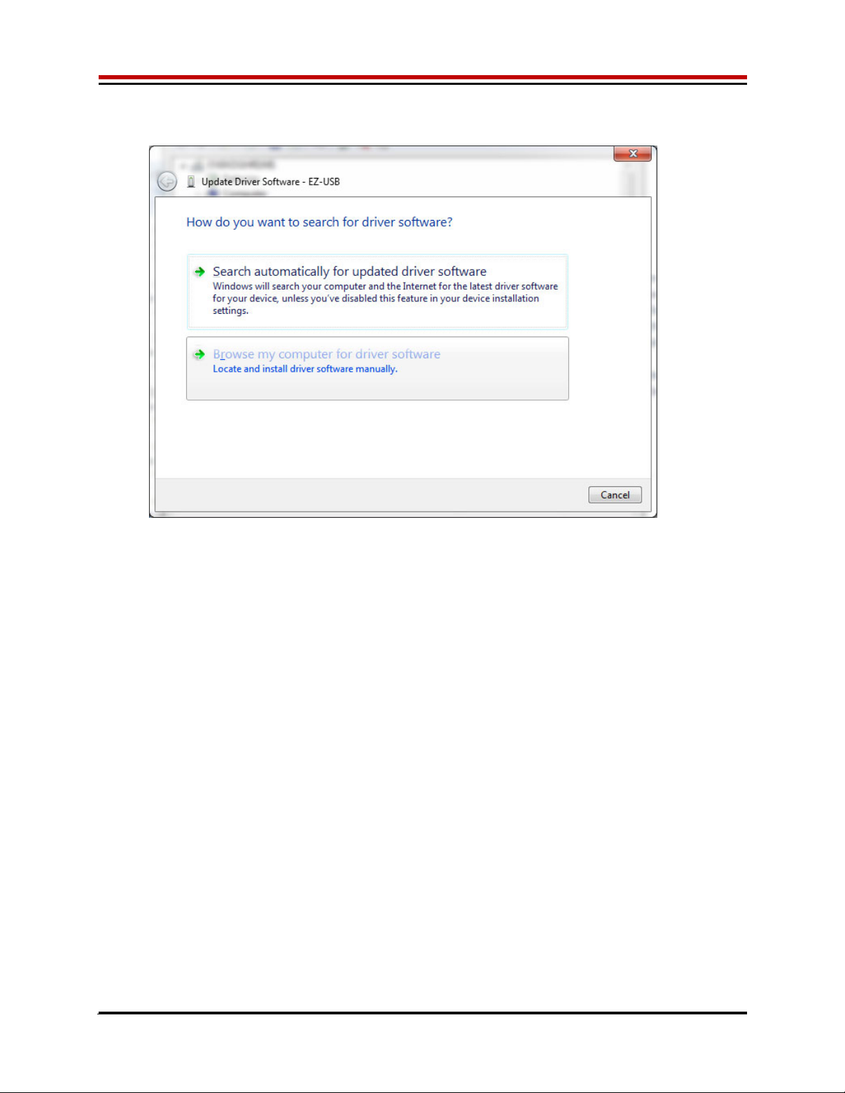
1.3.2.2.1 After connecting the USB cable from the PC to the “USB FX2 to Parallel” board,
navigate to the Device Manager screen on your computer and look for the EZ-USB
Icon. Right-Click on the EZ-USB Icon and select “Update Drive Software…”
Vesuvius EVM Getting Started Rev A2: 06/26/17
Copyright Elevate Semiconductor Corporation 2016 Page 9 of 30
1.3.2.2.2 Select “Browse my computer for driver software”.
1.3.2.2.3 Install driver from the newly installed folder on your computer:
Windows 7: \ElevATE Semi\EVM GUI\Elevate USB Driver\wlh-win7\(x64 or x86)
Select x64 for a 64-bit system.
Select x86 32-bit system.
Select “Next”. The USB driver will be installed.

Vesuvius EVM Getting Started Rev A2: 06/26/17
Copyright Elevate Semiconductor Corporation 2016 Page 10 of 30
1.3.2.3 Windows XP
To install the USB device driver on a Windows XP system, connect the USB port using the
included USB A/B cable. The USB port does not need any external power or need to be
connected to any other board for the device driver installation.
1.3.2.3.1 After connecting the USB cable from the PC to the USB port, the following window
appears. Select “No, not this time” and click Next.

Vesuvius EVM Getting Started Rev A2: 06/26/17
Copyright Elevate Semiconductor Corporation 2016 Page 11 of 30
1.3.2.3.2 Choose “Install from a list or specific location (Advanced)” and click Next.
1.3.2.3.3 Select the top radio button, and check “Include this location in the search.” Type the
following path into the text box.
Windows XP: \ElevATE Semi\EVM GUI\Elevate USB Driver\wxp\(x64 or x86)
Select x64 for a 64-bit system.
Select x86 32-bit system.
Select “Next”. The USB driver will be installed.

Vesuvius EVM Getting Started Rev A2: 06/26/17
Copyright Elevate Semiconductor Corporation 2016 Page 12 of 30
1.3.3 Reboot Machine
After the Vesuvius EVM and USB software is installed, it may be required to re-boot the machine.
1.3.4 Launching the Elevate Semiconductor Program
The user can launch the Elevate Semiconductor GUI from the Desktop, Start->Programs folder, or
Elevate SemiEVM GUI sub-directory.
1.3.5 Software Un-Installation
The Elevate Semiconductor demonstration program may be un-installed using the Add/Remove
Program from the Windows Control Panel.

Vesuvius EVM Getting Started Rev A2: 06/26/17
Copyright Elevate Semiconductor Corporation 2016 Page 13 of 30
2 Getting Started
The Vesuvius is shipped in a pre-configured state that allows a customer to evaluate the DPS Force
Voltage/Measure Current (FV/MI), Ganging and other features.
Note: Any external equipment providing digital signals into the Vesuvius device should only be enabled
after the Vesuvius is enabled. Also, the external equipment should be disabled prior to disabling the
Vesuvius.
2.1 Caution
The Vesuvius DUT Power Supply (DPS) is capable of delivering several amps of current. Configuring the
Vesuvius device and EVM into an extremely high power condition could cause permanent damage to the
Vesuvius device, EVM components, and/or external equipment.
2.2 Quick Start Instructions
2.2.1 Default Power Supply Option
1. Disable external power supply
2. Connect the power supplies cables (not provided) from the power supply to the Elevate
Semiconductor EVM Motherboard and Vesuvius loadboard; refer to Figure 3.
3. Connect the USB cable (provided) from the PC to the USB port.
4. Connect the EVM to any external equipment; refer to Section 2.3. Verify any external equipment is
disabled prior to connecting to the EVM board.
5. Setup Motherboard Jumpers; refer to Section 2.4
6. Ensure Vesuvius Loadboard Jumpers E2 – E10 and E14 are shorting pins 1 and 2 (towards back of
board).
7. Set external power supply voltages and current limits.
8. Enable external power supply.
9. Run the Elevate Semiconductor GUI software.
10. At the Force Voltage – Measure Current dialog box (refer to Figure 2 below):
a. Select the EVM Setup option based on the desired configuration, see Section 2.3
b. Select the Enable Supplies check box
c. Hit the Apply button to power up the Vesuvius device.
d. The software will also measure the current consumption. Figure 2 illustrates the expected
current readings.
11. At this point, the Vesuvius should be outputting the desired signal.

Vesuvius EVM Getting Started Rev A2: 06/26/17
Copyright Elevate Semiconductor Corporation 2016 Page 14 of 30
Figure 2: Expected Current Readings
The Reset System will put the EVM and Vesuvius device into the default state. The Reset System
should be issued whenever the power supply is powered OFF then ON. The Reset System is
automatically performed when the program is initially launched.

Vesuvius EVM Getting Started Rev A2: 06/26/17
Copyright Elevate Semiconductor Corporation 2016 Page 15 of 30
2.3 Default Configuration Setup Options
The EVM has several default options for configuring for device and loadboard.
Table 3: Vesuvius Default Configuration Options
Mode See Section # Brief Description
Hardware Rese
t
N/
A
A
ll re
g
isters default to the hardware default state.
Three-State
(
Hi
g
h-Z
)
N/
A
Puts DPS in three-state
(
hi
g
h-Z
)
. Opens all switches.
FV/MI 2.3.2
(default)
All Channels configured in FV/MI mode with I-Clamps disabled.
VFA = 3.0V, IR5, Sel-FB = SENSE, Con-FS = 1
Ch#0 FORCE and SENSE connected to TEST_NODE
FI/MV Channel 0 configured in FI/MV mode with the Voltage Clamps
enable. VFI = 51mA, IR5, Ch#0 FORCE connected to
TEST_NODE. 2 Ohm resistor connected to test node. VCH =
3.0V. VCL = -1.0V.
Ch#0/1 Ganging 2.3.4 All Channels (except Ch#1) configured in FV/MI mode with
I-Clamps disabled. Ch#1 configured into FV-Slave mode
Ch#0 VFA = 3.0V, IR5, Sel-FB = SENSE, Con-FS = 1
Ch#0 FORCE and SENSE connected to TEST_NODE
Ch#1 FORCE connected to TEST_NODE
Ch#0-7 Ganging 2.3.4 Ch#0 configured in FV/MI mode with I-Clamps disabled.
Channels#1-7 configured into FV-Slave mode
Ch#0 VFA = 3.0V, IR5, Sel-FB = SENSE, Con-FS = 1
Ch#0 FORCE and SENSE connected to TEST_NODE
Channel#1-7 FORCE connected to TEST_NODE
Gang Mode With
Slave Device
Dut 1 Ch#0 configured in FV/MI mode with I-Clamps disabled.
Channels#1-7 configured into FV-Slave mode. Dut 2 Ch#0-7
configured in FV-Slave mode.
Ch#0 VFA = 3.0V, IR5, Sel-FB = SENSE, Con-FS = 1
Ch#0 FORCE and SENSE connected to TEST_NODE
Channel#1-7 FORCE connected to TEST_NODE
2.3.1 Remote Kelvin Sense
Caution should be used when configuring the feedback (SENSE) path to ensure the DPS does not
become open loop. The software defaults the CPU-Sel-FB = 2 (SENSE) and Con-FS# = 1 (closed) to
ensure the loop is closed. After connecting any external equipment to the FORCE/SENSE SMAs (or
TEST_NODE), the user can then set Con-FS#=0 (open) to provide remote Kelvin sensing.
Vesuvius EVM Getting Started Rev A2: 06/26/17
Copyright Elevate Semiconductor Corporation 2016 Page 16 of 30
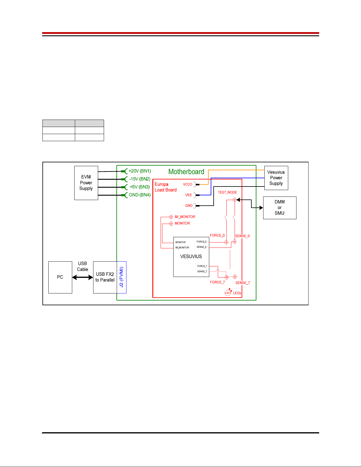
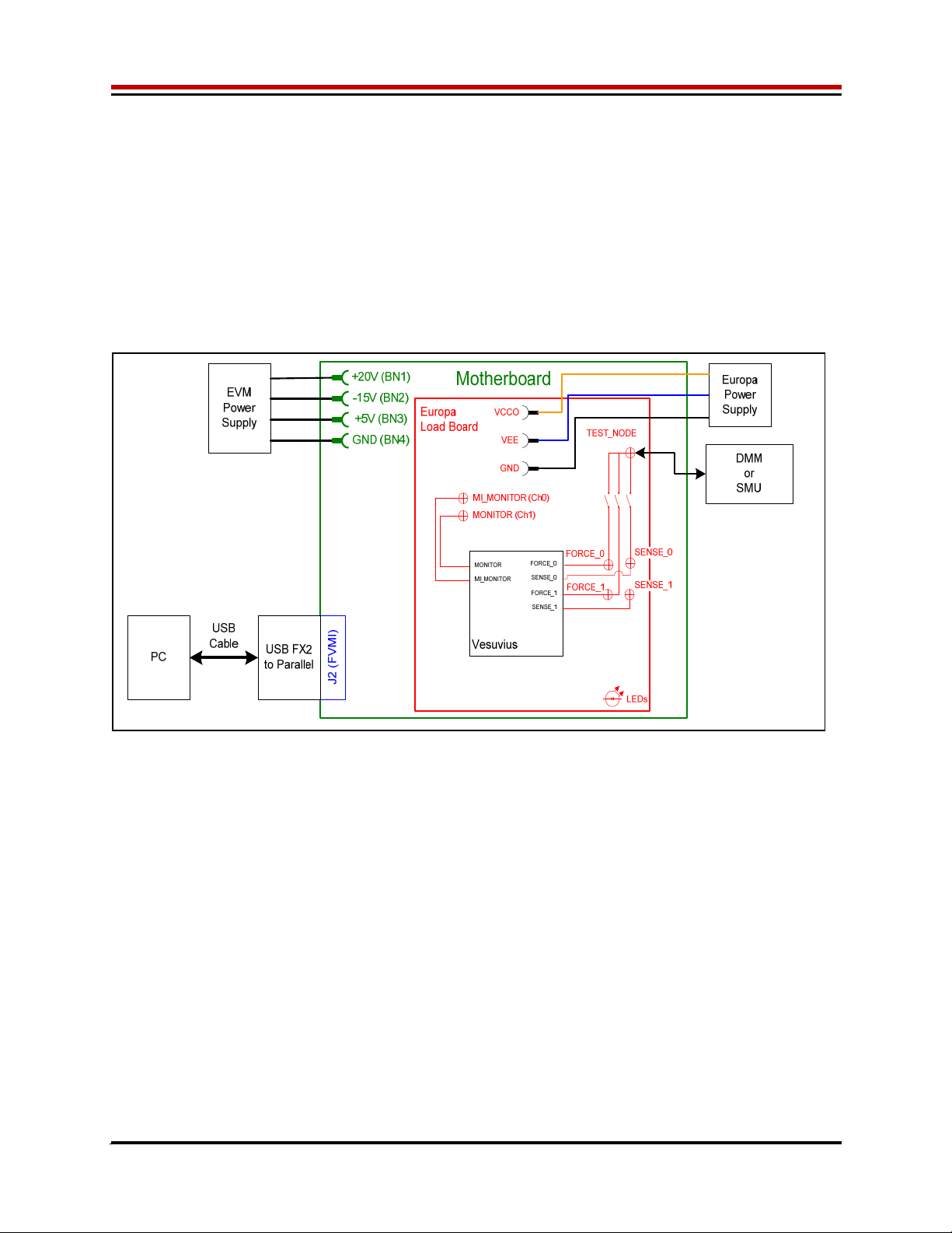
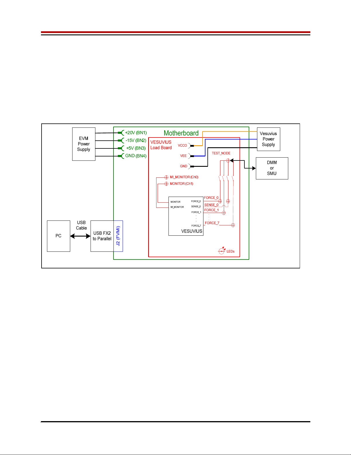
2.3.2 FV/MI Configuration
Figure 3 illustrates the recommended configuration for FV/MI (Force Voltage/Measure Current). After the
configuration is completed, use the Vesuvius->Master->Channel#0->Levels dialog box to change the
Vesuvius output levels. Use the Vesuvius Loadboard dialog box to connect other channels to the
TEST_NODE.
Both MI_MONITOR and MONITOR are configured to output Ch0/Ch1 MI-S
If using an external source measurement unit (SMU), the SMU should be configured in the opposite mode
as Vesuvius.
V
esuvius SMU
FV/MI FI/MV
FI/MV FV/MI
Figure 3: Vesuvius EVM FV/MI Simplified Block Diagram
Vesuvius EVM Getting Started Rev A2: 06/26/17
Copyright Elevate Semiconductor Corporation 2016 Page 17 of 30
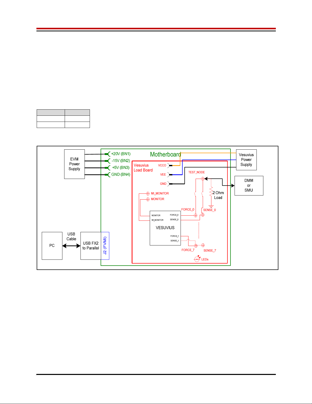
2.3.3 FI/MV Configuration
Figure 4 Illustrates the recommended configuration for FI/MV (Force Current/Measure Voltage). After the
configuration is completed, use the Vesuvius->Master->Channel#0->Levels dialog box to change the
Vesuvius output levels. Use the Vesuvius Loadboard dialog box to connect or disconnect resistors
and capacitors to the FORCE output.
The MONITOR is configured to measure the voltage between the FORCE output and GROUND. This
voltage is used for the Voltage Clamps (VCH/VCL)
If using an external source measurement unit (SMU), the SMU should be configured in the opposite mode
as Vesuvius.
V
esuvius SMU
FV/MI FI/MV
FI/MV FV/MI
Figure 4: Vesuvius EVM FI/MV Simplified Block Diagram
Vesuvius EVM Getting Started Rev A2: 06/26/17
Copyright Elevate Semiconductor Corporation 2016 Page 18 of 30
2.3.4 Channel#0 and Channel#1 Ganging (Merging) Configuration
5 illustrates the recommended configuration for the ganging application. Channel#0 is configured in FV
mode (Master) in Remote Sense while Channel#1 is configured in FV (Slave) mode. Both Channel#0
and Channel#1 FORCE pins are connected to the TEST_NODE SMA. Channel#0 SENSE is also
connected to TEST_NODE which provides the remote Kelvin Sense return path.
The MI_MONITOR is configured to output the Channel#0 MI-S. The MONITOR is configured to output
the Channel#1 MI-S.
Channels 2-7 are configured in FV/MI mode.
Figure 5: Vesuvius EVM Ganging Configuration Simplified Block Diagram
Vesuvius EVM Getting Started Rev A2: 06/26/17
Copyright Elevate Semiconductor Corporation 2016 Page 19 of 30
2.3.5 All channels in Ganged (Merging) Configuration
5 illustrates the recommended configuration for the ganging application of all channels. Channel#0 is
configured in FV mode (Master) in Remote Sense while Channels#1-7 are configured in FV (Slave)
mode. Channel#0-7 FORCE pins are connected to the TEST_NODE SMA. Channel#0 SENSE is also
connected to TEST_NODE which provides the remote Kelvin Sense return path.
The MI_MONITOR is configured to output the Channel#0 MI-S. The MONITOR is configured to output
the Channel#1 MI-S.
Channels 2-7 are configured in FV/MI mode.
Figure 6: Vesuvius EVM All Channels Ganging Configuration Simplified Block Diagram

Vesuvius EVM Getting Started Rev A2: 06/26/17
Copyright Elevate Semiconductor Corporation 2016 Page 20 of 30
2.4 Motherboard Jumper and SMA Definition
Table 4 lists the Motherboard Jumper/SMA definitions for the Vesuvius EVM.
Table 4: Motherboard SMA and Jumper Definitions (Vesuvius Input Signals)
TC# Jumpe
r
Usa
g
e Confi
g
uration
TC30 E12 PLL_CK
(
Fs
y
nc
)
Short Pin 1 & 2. towards back of board
TC29 E11 PLL_CK*
(
Fs
y
nc
)
Short Pin 1 & 2. towards back of board
TC28 E14 TJ
(
V
)
Short Pin 2 & 3. towards front of board
TC27 E15 EXT_MON_OE Short Pin 1 & 2. towards back of board
TC26 E2 EN Short Pin 1 & 2: source from latch
Short Pin 2 & 3: source from SM
A
TC25 E10 SLAVE_RESET Short Pin 1 & 2: source from latch
Short Pin 2 & 3: source from SM
A
TC24 E9 SLAVE_STB Short Pin 1 & 2: source from latch
Short Pin 2 & 3: source from SM
A
TC23 E8 Short Pin 1 & 2: source from latch
Short Pin 2 & 3: source from SM
A
TC22 E7 DIG_BANK_SEL Short Pin 1 & 2: source from latch
Short Pin 2 & 3: source from SM
A
TC21 E1 SDI
_
RCK Short Pin 1 & 2. towards back of board
TC20 E6 DATA_3/DATA_7 Short Pin 1 & 2: source from latch
Short Pin 2 & 3: source from SM
A
TC19 E5 DATA_2/DATA_6 Short Pin 1 & 2: source from latch
Short Pin 2 & 3: source from SM
A
TC18 E4 DATA_1/DATA_5 Short Pin 1 & 2: source from latch
Short Pin 2 & 3: source from SM
A
TC17 E3 DATA_0/DATA_4 Short Pin 1 & 2: source from latch
Short Pin 2 & 3: source from SM
A
TC16 E13 N/
A
Don’t care
TC15 E20 N/
A
Don’t care
The following table defines the Vesuvius output signals. These are always present at the motherboard
SMAs.
Table 5: Motherboard SMA Definitions (Vesuvius Output Signals)
TC# MB EVM
TC14 OT*
TC13
A
LARM*
TC12 Unused
TC11 GANG_IN_SLAVE
TC10 CPU_CK
TC9 GANG7_OUT
TC8 GANG5_OUT
TC6 GANG3_OUT
TC5 GANG1_OUT
TC4 RESET
TC3 CPU_STB
TC2 CPU_SDIO
This manual suits for next models
1
Table of contents
Other ElevATE Semiconductor Motherboard manuals


