ElevATE Semiconductor Venus Series User manual
ISL55161/2/3/4 and Venus Family EVM Getting Started REV G03: 2018-06-21
Copyright Elevate Semiconductor 2012 Page 1 of 28
ISL55161/2/3/4 and Venus Family EVM Getting
Started
REV G03: 2018-06-21
This document contains information on a product under development and the material is
subject to change.

ISL55161/2/3/4 and Venus Family EVM Getting Started REV G03: 2018-06-21
Copyright Elevate Semiconductor 2012 Page 2 of 28
Table of Contents
1Introduction ..........................................................................................................................................................4
1.1Unpacking - EVM Contents ........................................................................................................................ 4
1.2Recommended Test and Measurement Setup ........................................................................................... 4
1.2.1Power Supply ......................................................................................................................................... 4
1.2.2PC Controller ......................................................................................................................................... 4
1.3Software Installation ................................................................................................................................... 5
1.3.1ISL55161/2/3/4 and Venus Family UIP Installation .............................................................................. 5
1.3.2USB Device Driver Installation ............................................................................................................. 5
1.3.3Reboot Machine ................................................................................................................................... 11
1.3.4Launching the EVM Program .............................................................................................................. 11
1.3.5Software Un-Installation ...................................................................................................................... 11
2Getting Started ....................................................................................................................................................12
2.1Loadboard and Motherboard Revisions .................................................................................................. 12
2.2Venus and ISL Product Families .............................................................................................................. 12
2.3Default Configuration Setup Options ...................................................................................................... 12
2.3.1Real Time Data .................................................................................................................................... 13
2.3.2Ring Oscillator Mode (No Pulse Generator) ........................................................................................ 14
2.3.3LVDS Outputs Real Time Data ........................................................................................................... 15
2.3.4Channel #0 in Real Time DATA and Channel #1 in Compare Only ................................................... 17
2.3.5PMU Force Voltage or Force Current Modes ...................................................................................... 18
2.3.6PMU Chan#0 in FV and Chan#1 in FI ................................................................................................ 19
2.3.7Real Time PMU SV & Driver DVL using EN or SV Inputs ............................................................... 20
2.4Quick Start Instructions ............................................................................................................................ 22
2.5Motherboard Jumper Definition .............................................................................................................. 23
2.6EVM Menu Dialog Boxes .......................................................................................................................... 24
3EVM Loadboard Detailed Description...............................................................................................................25
3.1ADC and Analog Mux ............................................................................................................................... 26
3.2Venus Loadboard Controller .................................................................................................................... 26
4Layout Considerations........................................................................................................................................27
4.1Conjugate Termination ............................................................................................................................. 27
4.2CAP DVH/DVL/VTT ................................................................................................................................ 27
5Document Revision History................................................................................................................................28

ISL55161/2/3/4 and Venus Family EVM Getting Started REV G03: 2018-06-21
Copyright Elevate Semiconductor 2012 Page 3 of 28
List of Figures
Figure 1: Installation Directory Structure ...................................................................................................... 5
Figure 2: Real Time DATA Block Diagram ................................................................................................ 13
Figure 3: Ring Oscillator Block Diagram .................................................................................................... 14
Figure 4: LVDS Output Real Time DATA Block Diagram .......................................................................... 1 6
Figure 5: Chan#0 Driver Mode and Chan#1 Compare Only Block Diagram ............................................. 17
Figure 6: PMU FV/FI Block Diagram .......................................................................................................... 18
Figure 7: PMU Chan# 0 FV and Chan #1 FI Block Diagram ..................................................................... 19
Figure 8: Toggle PMU FV (SV) and Driver DVL Block Diagram ................................................................. 20
Figure 9: Expected Current Readings ........................................................................................................ 22
Figure 10: Device Config Menu Options .................................................................................................... 24
Figure 11: Venus Loadboard Detailed Block Diagram ............................................................................... 25
List of Tables
Table 1: EVM Contents ................................................................................................................................ 4
Table 2: Power Supply Requirements ......................................................................................................... 4
Table 3: Motherboard Jumper Definitions .................................................................................................. 23
Table 4: FVMI Analog Mux – VINPOS(A) & VINNEG(A) Mapping ............................................................ 26
Table 5: Loadboard C-Bit (J6) Signal Definitions ....................................................................................... 26
Table 6: Venus Loadboard Latches (U3) Signal Definitions ...................................................................... 26

ISL55161/2/3/4 and Venus Family EVM Getting Started REV G03: 2018-06-21
Copyright Elevate Semiconductor 2012 Page 4 of 28
1 Introduction
Congratulations on your purchase of the Elevate Semiconductor ISL55161/2/3/4 and Venus Family
evaluation system. You will find that it serves as an invaluable development platform to help get your
product to market in the shortest possible time. The ISL55161, ISL55162, ISL55163, ISL55164, Venus,
Venus3, and Venus4 products will be referred to as “Venus” in this document unless otherwise stated
below. The Evaluation Module (EVM) and Graphical User Interface (GUI) allow the customer to
demonstrate and evaluate performance and functionality.
This document provides the instructions to install, setup, and operate the Venus EVM. Refer to the
Elevate Semiconductor EVM User’s Guide for a detailed description of the EVM system.
1.1 Unpacking - EVM Contents
Please check the contents of the EVM shipping carton to make sure you have received all of the items
listed in Table 1. The system is already configured for the best setup, except for connections to the
power supply, PC controller, and test equipment.
Table 1: EVM Contents
Qt
y
Description
1 ea. EVM S
y
stem
(
3 boards: Motherboard, FVMI Board, Venus Loadboard
)
1 ea. ISL55161/2/3/4 and Venus Famil
y
EVM Gettin
g
Started
(
this document
)
1 ea. EVM Contents Lis
t
1 ea. User Interface Pro
g
ram Installation Flash Drive
1 ea. USB
A
/B Cable
1.2 Recommended Test and Measurement Setup
Oscilloscope, Differential Pulse Generators, DMMs, and Source Measure Unit
1.2.1 Power Supply
Table 2 provides the required power supplies and current rating. The power supplies are connected
using standard banana plugs. The customer needs to provide the power supply cables.
Table 2: Power Supply Requirements
Suppl
y
Current Ratin
g
+20V 1
A
+5V 1
A
-15V 1
A
1.2.2 PC Controller
To use the EVM User Interface Program (UIP), a PC with the following configuration is required:
Windows XP, Windows 2007, Windows 2008, Windows 2010
USB Port

ISL55161/2/3/4 and Venus Family EVM Getting Started REV G03: 2018-06-21
Copyright Elevate Semiconductor 2012 Page 5 of 28
1.3 Software Installation
There are 2 steps to install the ISL55161/2/3/4 and Venus Family demonstration program.
1. Install the ISL55161/2/3/4 and Venus Family UIP from the Flash Drive.
2. Install the USB driver.
Figure 1 illustrates the default directory structure. The user may change the <root dir> during the
installation.
Figure 1: Installation Directory Structure
1.3.1 ISL55161/2/3/4 and Venus Family UIP Installation
To install the ISL55161/2/3/4 and Venus Family software package, run the SETUP program on the
distribution Flash Drive and follow the prompts. The ElevATE.exe executable will be installed in the EVM
GUI sub-directory. In addition, a short cut will be installed onto the desktop and in the Start->Programs
folder. The Start->Programs folder also contains links to the different EVM User’s Guide, and
documentation folders.
1.3.2 USB Device Driver Installation
Follow section 1.3.2.1 for installation instructions on the Windows 10/8 operating systems, section 1.3.2.2
for instructions for Windows 7, or section 1.3.2.3 for Windows XP
1.3.2.1 Window 10/8
To install the USB driver on Windows 10/8, the Driver Signature Verification needs to be disabled.
This is accomplished using the following method.
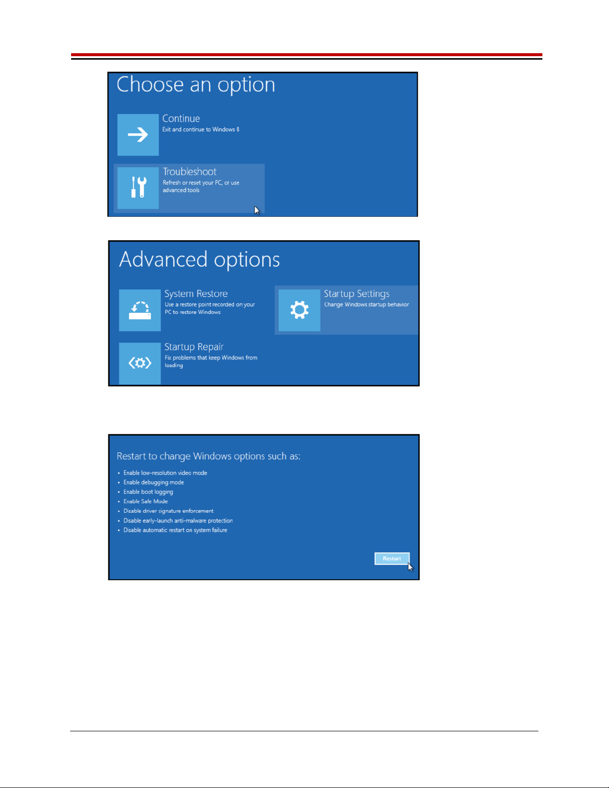
1.3.2.1.1 Enter the Troubleshoot menu. Click “Restart” from the power options menu and hold
down the “Shift” key at the same time. Once the computer has rebooted, you will be able
to choose the Troubleshoot option.
ISL55161/2/3/4 and Venus Family EVM Getting Started REV G03: 2018-06-21
Copyright Elevate Semiconductor 2012 Page 6 of 28
1.3.2.1.2 Select “Advanced options” and “Startup Settings”.
1.3.2.1.3 You need to restart your computer one last time to modify boot time configuration
settings.
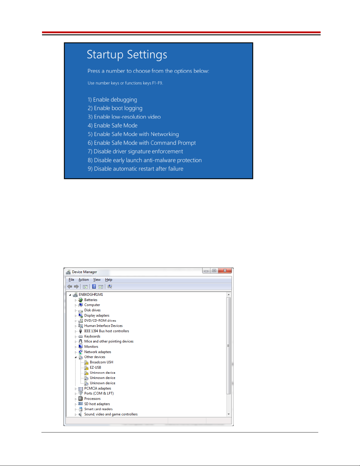
1.3.2.1.4 You will be given a list of startup settings, including “Disable driver signature
enforcement”. To choose the setting, you need to press the “F7” key. This will disable the
driver signature enforcement until the computer is rebooted.
ISL55161/2/3/4 and Venus Family EVM Getting Started REV G03: 2018-06-21
Copyright Elevate Semiconductor 2012 Page 7 of 28
1.3.2.1.5 Continue with section 1.3.2.2 to finish installation of USB driver except choose the
windows 10 or windows 8 option.
1.3.2.2 Windows 7
To install the USB device driver on a Windows 7 system, connect the USB port using the included
USB A/B cable. The USB port does not need any external power or need to be connected to any
other board for the device driver installation.
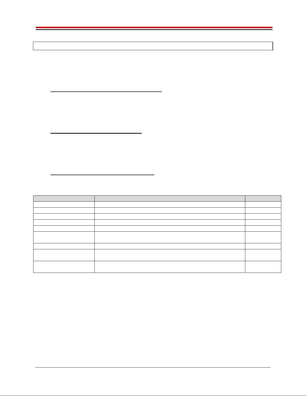
1.3.2.2.1 After connecting the USB cable from the PC to the “USB FX2 to Parallel” board, navigate to
the Device Manager screen on your computer and look for the EZ-USB Icon. Right-Click
on the EZ-USB Icon and select “Update Drive Software…”

ISL55161/2/3/4 and Venus Family EVM Getting Started REV G03: 2018-06-21
Copyright Elevate Semiconductor 2012 Page 8 of 28
1.3.2.2.2 Select “Browse my computer for driver software”.
1.3.2.2.3 Install driver from the newly installed folder on your computer:
Windows 7: \ElevATE Semi\EVM GUI\Elevate USB Driver\wlh-win7\(x64 or x86)
Select x64 for a 64-bit system.
Select x86 32-bit system.
Select “Next”. The USB driver will be installed.

ISL55161/2/3/4 and Venus Family EVM Getting Started REV G03: 2018-06-21
Copyright Elevate Semiconductor 2012 Page 9 of 28
1.3.2.3 Windows XP
To install the USB device driver on a Windows XP system, connect the USB port using the
included USB A/B cable. The USB port does not need any external power or need to be
connected to any other board for the device driver installation.
1.3.2.3.1 After connecting the USB cable from the PC to the port, the following window appears.
Select “No, not this time” and click Next.

ISL55161/2/3/4 and Venus Family EVM Getting Started REV G03: 2018-06-21
Copyright Elevate Semiconductor 2012 Page 10 of 28
1.3.2.3.2 Choose “Install from a list or specific location (Advanced)” and click Next.
1.3.2.2.3 Select the top radio button, and check “Include this location in the search.” Type the
following path into the text box.
Windows XP: \ElevATE Semi\EVM GUI\Elevate USB Driver\wxp\(x64 or x86)
Select x64 for a 64-bit system.
Select x86 32-bit system.
Select “Next”. The USB driver will be installed.

ISL55161/2/3/4 and Venus Family EVM Getting Started REV G03: 2018-06-21
Copyright Elevate Semiconductor 2012 Page 11 of 28
1.3.3 Reboot Machine
After the EVM and USB software is installed, it is recommended to re-boot the machine.
1.3.4 Launching the EVM Program
The user can launch the EVM GUI from the desktop, Start->Programs folder, or EVM GUI sub-directory.
1.3.5 Software Un-Installation
The ElevATE EVM demonstration program may be un-installed using the uninstall window from the
Windows Control Panel. The program can be found under the name “ElevATE EVM”.
ISL55161/2/3/4 and Venus Family EVM Getting Started REV G03: 2018-06-21
Copyright Elevate Semiconductor 2012 Page 12 of 28
2 Getting Started
The EVM is shipped in a pre-configured state that allows a customer to evaluate the basic driver and
comparator output performance as well as the PMU Force Voltage (FV) / Force Current (FI) modes.
Figure 2 provides an illustration of the recommended interconnections to the Venus EVM. However due
to equipment availability, the EVM can easily and quickly be configured for different options.
2.1 Loadboard and Motherboard Revisions
This document only supports the Loadboard Rev F+ and the Motherboard Rev D+.
For earlier Loadboard & Motherboard revisions, please contact Elevate Semiconductor for the appropriate
documentation.
2.2 Venus and ISL Product Families
The Loadboard supports all of the various Venus and ISL Products: Venus, Venus3, Venus4, ISL55161,
ISL55162, ISL55163, and ISL55164. The Venus4, ISL55161and ISL55163 devices redefined a handful
of pins. To support the different products, the loadboard installs/removes several components to support
the different features. Refer to Section 3 for details. Also refer to the schematic and datasheets.
2.3 Default Configuration Setup Options
The EVM has several default options for providing a DATA stream and/or configuring for PMU mode.
Each of the default configurations below may not be available for every product.
Mode Brief Description Reference
Hardware Rese
t
A
ll re
g
isters default to the hardware default state. None
Three-State
(
Hi
g
h-Z
)
Puts Driver and PMU in three-state
(
hi
g
h-Z
)
. None
Real Time Data
(
default
)
Use motherboard DATA# SMA connectors Section 2.3.1
Rin
g
Oscillator Mode Use Internal Rin
g
Oscillator Section 2.3.2
LVDS Output Levels Use Channel #0 and #1 create a low-volta
g
e differential si
g
nal Section 2.3.3
Chan#0 RT DATA
Chan#1 Compare Onl
y
Configures Venus so can evaluate Drive/Compare on Channel #0
and Compare Onl
y
on Channel #1
Section 2.3.4
PMU FV or FI Confi
g
ures both channels to the desired mode Section 2.3.5
PMU Chan #0 FV and
Chan #1 FI
Use the other channel to provide current/voltage load Section 2.3.6
Real Time SV / DVL Use Real Time EN input to toggle between SV (FV) and DVL.
Optionall
y
can use SV input to to
gg
le between SV and HiZ.
Section 2.3.7
ISL55161/2/3/4 and Venus Family EVM Getting Started REV G03: 2018-06-21
Copyright Elevate Semiconductor 2012 Page 13 of 28
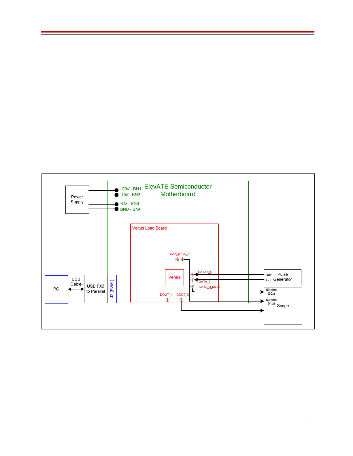
2.3.1 Real Time Data
Figure 2 illustrates the recommended EVM configuration. This option sources the DATA# from a Pulse
Generator. The ENABLE# is set to CPU Control and high (always enabled). The SV# is set to CPU
Control and low (always disabled/open). The DATA# input term is set to 100 Ohm. This option works
best if the customer has a differential pulse generator with at least a 200mV swing.
The DATA#_MON and Comparator Outputs (CA#) have a 953 ohm pick-off. The scope should be set to
50 ohm termination with an attenuation factor of 20.
Note: Channel #1 could be connected in a similar fashion, not shown in diagram. Both channels are
configured the same.
If the customer only has a single ended pulse generator, then the DATAN# can be tied to 1.0V (Vterm);
the Vterm must be able to handle any current flow required for proper termination. Set the pulse
generator to a 0.0V to 3.0V swing. Select the Single Ended RT Data from the EVM Setup configuration
menu. The DATA# input term is set to NONE.
Figure 2: Real Time DATA Block Diagram

ISL55161/2/3/4 and Venus Family EVM Getting Started REV G03: 2018-06-21
Copyright Elevate Semiconductor 2012 Page 14 of 28
2.3.2 Ring Oscillator Mode (No Pulse Generator)
Figure 3 illustrates a possible configuration for customers without any pulse generator. This option uses
the Ring Oscillator feature to generate a ~20 MHz pulse with a ~15 nS pulse width. All deskews are
enabled and set to zero delay. Both channels are configured the same. This option is not available on
the ISL55163.
The Comparator Outputs (CA#) have a 953 ohm pick-off. The scope should be set to 50 ohm termination
with an attenuation factor of 20.
Figure 3: Ring Oscillator Block Diagram

ISL55161/2/3/4 and Venus Family EVM Getting Started REV G03: 2018-06-21
Copyright Elevate Semiconductor 2012 Page 15 of 28
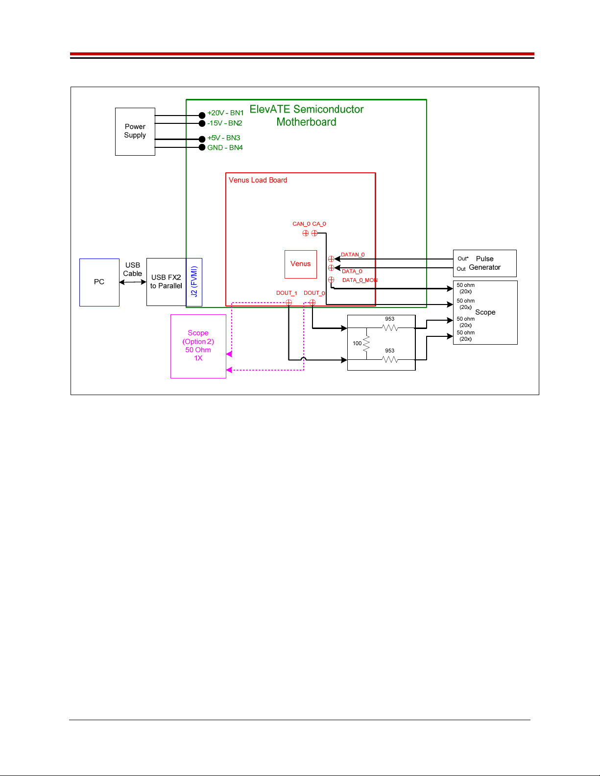
2.3.3 LVDS Outputs Real Time Data
Figure 2 illustrates the EVM configuration for generating LVDS Outputs. A Low Voltage Differential
Signal (LVDS) is defined as Vcm=1.25V and Vswing=350mV into a 100 Ohm termination.
The input data stream is feed into DATA#0. Channel #1 also sources its data from DATA #0 using
Venus’s internal cross point switch. The Channel #1 signal is then inverted using the DATA-XOR feature.
The driver DVH/DVL levels are programmed to 1.6V and 0.9V respectively. The ENABLE# is set to CPU
Control and high (always enabled). The SV# is set to CPU Control and low (always disabled/open). The
DATA# input term is set to 100 Ohm.
The user is responsible for programming the deskew values such that the 2 waveforms align. Failure to
program the deskew values could result in poor output waveforms. The Driver Deskew Delay and Falling
Edge Adjust (FEA) are enabled and set to 0.
There are 2 options to connecting the outputs to a scope.
Scope setup option 1: (true LVDS levels)
Connect a 100 Ohm resistor between DOUT0 and DOUT1. Use a 953 Ohm pick off connected to the
Scope’s 50 Ohm input. This will result in a 20X attenuation, the scope should be configured accordingly.
The 953 Ohm pick off is used to minimize reflections, this will also cause a 5% drop in the output
voltages.
Scope setup option 2: (pseudo LVDS levels)
Connect the DOUT0 and DOUT1 to the Scope’s 50 Ohm input, the probe attenuation should be set to 1.
The scope’s two 50 Ohm resistors are used to create a 100 Ohm termination between Channel #0 and
Channel #1. The main difference is that the Vcm will be 0V (GND) instead of 1.25V. The user needs to
program the driver DVH/DVL to +0.350V and -0.350V respectively.
ISL55161/2/3/4 and Venus Family EVM Getting Started REV G03: 2018-06-21
Copyright Elevate Semiconductor 2012 Page 16 of 28
Figure 4: LVDS Output Real Time DATA Block Diagram
ISL55161/2/3/4 and Venus Family EVM Getting Started REV G03: 2018-06-21
Copyright Elevate Semiconductor 2012 Page 17 of 28
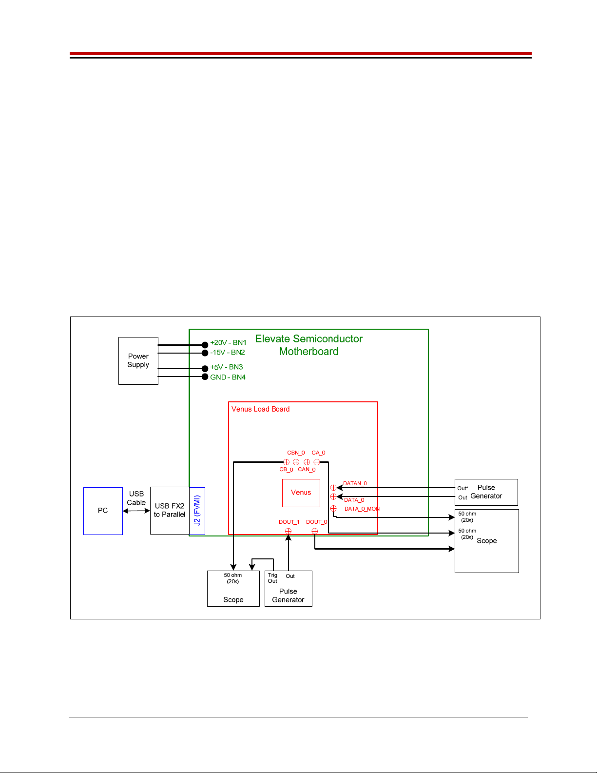
2.3.4 Channel #0 in Real Time DATA and Channel #1 in Compare Only
Figure 5 illustrates a possible configuration for customers to evaluate the Driver and Compare only
modes. To evaluate the Driver, connect a differential pulse generator to the DATA_0 SMAs. To
evaluate the Comparator Only mode, connect a single-ended pulse generator into the Venus DOUT_1
SMA.
Channel#1 will be set to VTT Mode (50 Ohm termination) with the VTT Level set to 1.5V. The Channel#1
comparator thresholds are also set to 1.5V. The pulse generator should be set to swing around 1.5V. If
other pulse generator levels are required, change the Venus VTT level and comparator thresholds as
required.
Note: to put Channel#1 into HiZ mode instead of VTT mode, change the DR-Mode setting found in
Product(ISL55161, ISL55162, etc…)->Channel 1->Driver Path Config
The 2 channels will run asynchronously since the 2 pulse generators are asynchronous.
The DATA#_MON and Comparator Outputs (CA#) have a 953 ohm pick-off. The scope should be set to
50 ohm termination with an attenuation factor of 20.
Figure 5: Chan#0 Driver Mode and Chan#1 Compare Only Block Diagram
ISL55161/2/3/4 and Venus Family EVM Getting Started REV G03: 2018-06-21
Copyright Elevate Semiconductor 2012 Page 18 of 28
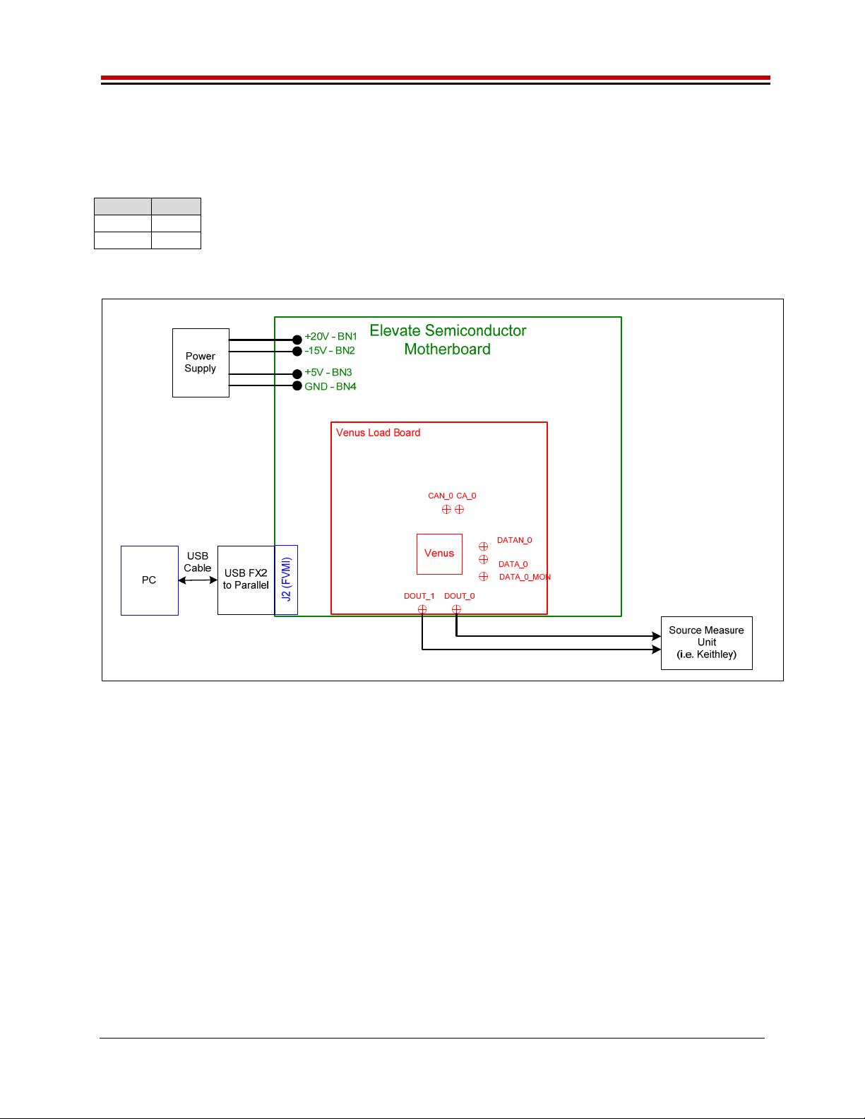
2.3.5 PMU Force Voltage or Force Current Modes
Figure 6 illustrates the recommended configuration for PMU FV/FI evaluation. The external measurement
unit (MU) should be configured in the opposite mode as Venus. After the configuration is completed, use
the PMU FV/FI Levels dialog box the change the Venus output levels.
V
enus MU
FVMI FIMV
FIMV FVMI
Figure 6: PMU FV/FI Block Diagram

ISL55161/2/3/4 and Venus Family EVM Getting Started REV G03: 2018-06-21
Copyright Elevate Semiconductor 2012 Page 19 of 28
2.3.6 PMU Chan#0 in FV and Chan#1 in FI
Figure 6 illustrates the configuration for PMU Chan #0 FV and Chan #1 FI evaluation. The other channel
is used to provide a proper load (current load or voltage load depending on which channel is being
evaluated). This option is useful when the customer doesn’t have an external measurement unit.
Instead, the customer can use two DMMs to evaluate the Venus PMU.
DMM Mode Connection
Measure Volta
g
e Use a ‘T’ connector to monitor DOUT_0 relative to GND
Measure Current Connect in series between DOUT_0 and DOUT_1
Figure 7: PMU Chan# 0 FV and Chan #1 FI Block Diagram
ISL55161/2/3/4 and Venus Family EVM Getting Started REV G03: 2018-06-21
Copyright Elevate Semiconductor 2012 Page 20 of 28
2.3.7 Real Time PMU SV & Driver DVL using EN or SV Inputs
Figure 8 illustrates the configuration that uses the EN input to toggle the DOUT output between PMU FV
(SV) and Driver DVL. In this application, the PMU FV is used to create the Super Voltage (SV) output.
The PMU FV can output up to the VCC_SV (13V) supply minus headroom while the Driver uses the VCC
(8V) supply.
The Driver is set to Real-Time Enable with CPU-DATA=0 (DVL); DVL is set to 0V. The PMU is set to
Real-Time using the inverted Enable signal. The PMU is set to 12V in VR2, IR7 (32mA), and Tight
feedback. The 32mA is chosen since that has the fastest response time. The PMU needs to be in Tight
loopback to prevent the PMU from going into open loop when the SV switch is open.
EN Input Driver State SV Switch DOUT Output
1 Enabled Open DVL
(
0V
)
0 Disabled Closed FV
(
12V
)
Channel #0: Short E5 & E6 (on Motherboard) between Pin 2-3 (towards front of board)
Channel #0: Connect differential pair to EN_0 & ENN_0 SMA connectors (on Motherboard)
Transitioning from DVL to FV (SV) requires about 100nS. Therefore the pulse generator should be set
accordingly.
Real Time SV Option
To optionally use the Real Time SV input to toggle between PMU FV (SV) and HiZ:
Start with the Real Time SV / DVL using Enable setup
Set Sel-SV-EN = SV in the Product(ISL55161, ISL55162, etc…)->Channel 0->Driver Path
Config dialog box
Channel #0: Short E7 (on Motherboard) between Pin 2-3 (towards front of board)
Channel #0: Connect pulse generator to SV_0 SMA connector (on Motherboard)
The Driver must be disabled. Either set the EN inputs to a static low or set Sel-RT-EN = CPU EN
and set CPU-EN Value = Low.
SV Input SV Switch DOUT Output
0 Open HiZ
1 Closed FV
(
12V
)
Note: DOUT should be connected to a Rload so DOUT gets pulled to GND when DOUT is in HiZ.
Figure 8: Toggle PMU FV (SV) and Driver DVL Block Diagram
This manual suits for next models
7
Table of contents
Other ElevATE Semiconductor Motherboard manuals


