ELEVATE ISL55180 EVM User manual

ISL55180 EVM Getting Started Rev A04: 11/28/2012
Copyright Elevate Semiconductor Corporation 2012 Page 1 of 20
ISL55180 EVM Getting Started
Rev A04: 11/28/2012
This document contains information on a product under development. The parametric
information contains target parameters that are subject to change.

ISL55180 EVM Getting Started Rev A04: 11/28/2012
Copyright Elevate Semiconductor Corporation 2012 Page 2 of 20
Table of Contents
1Introduction..........................................................................................................................................................4
1.1 Unpacking - ISL55180 EVM Contents ......................................................................................................4
1.2 Recommended Test and Measurement Setup...........................................................................................5
1.2.1 Power Supply.........................................................................................................................................5
1.2.2 PC Controller.........................................................................................................................................5
1.2.3 DMM or Source Measurement Unit ......................................................................................................5
1.3 Software Installation ...................................................................................................................................6
1.3.1 ISL55180 EVM UIP Installation...........................................................................................................6
1.3.2 Parallel Port (ParPort2K) Installation....................................................................................................6
1.3.3 Reboot Machine.....................................................................................................................................6
1.3.4 Launching the Elevate Semiconductor Program....................................................................................6
1.3.5 Software Un-Installation........................................................................................................................6
2Getting Started......................................................................................................................................................7
2.1 Caution .........................................................................................................................................................7
2.2 Quick Start Instructions..............................................................................................................................7
2.2.1 Default Power Supply Option................................................................................................................7
2.2.2 Switching Regulator Supply Option......................................................................................................9
2.3 Default Configuration Setup Options ......................................................................................................10
2.3.1 Remote Kelvin Sense...........................................................................................................................10
2.3.2 FV/MI Configuration...........................................................................................................................11
2.3.3 Channel#0 and Channel#1 Ganging (Merging) Configuration............................................................12
2.4 Motherboard Jumper and SMA Definition.............................................................................................13
2.5 ISL55180 Loadboard Jumper Definitions...............................................................................................14
2.6 ISL55180 EVM Menu and Dialog Boxes.................................................................................................15
3ISL55180 EVM Loadboard Detailed Description..............................................................................................18
3.1 ISL55180 EVM Loadboard Controller....................................................................................................19
4Document Revision History................................................................................................................................20

ISL55180 EVM Getting Started Rev A04: 11/28/2012
Copyright Elevate Semiconductor Corporation 2012 Page 3 of 20
List of Figures
Figure 1: Installation Directory Structure......................................................................................................6
Figure 2: Expected Current Readings..........................................................................................................8
Figure 3: ISL55180 EVM FV/MI Simplified Block Diagram........................................................................11
Figure 4: ISL55180 EVM Ganging Configuration Simplified Block Diagram.............................................12
Figure 5: Device Config Menu Options......................................................................................................15
Figure 6: ISL55180 Configuration Dialog Box............................................................................................16
Figure 7: ISL55180 DC Levels Dialog Box ................................................................................................16
Figure 8: ISL55180 DAC Configuration Dialog Box...................................................................................17
Figure 9: ISL55180 Central Register Dialog Box.......................................................................................17
Figure 10: ISL55180 EVM Detailed Block Diagram...................................................................................18
Figure 11: Controller Section Detailed Block Diagram ..............................................................................19
List of Tables
Table 1: ISL55180 EVM Contents ................................................................................................................4
Table 2: Power Supply Requirements .........................................................................................................5
Table 3: ISL55180 Default Configuration Options .....................................................................................10
Table 4: Motherboard SMA and Jumper Definitions (ISL55180 Input Signals).........................................13
Table 5: Motherboard SMA Definitions (ISL55180 Output Signals) ..........................................................13
Table 6: ISL55180 Loadboard Jumper Definitions ....................................................................................14

ISL55180 EVM Getting Started Rev A04: 11/28/2012
Copyright Elevate Semiconductor Corporation 2012 Page 4 of 20
1 Introduction
Congratulations on your purchase of an Elevate Semiconductor ATE ISL55180 EVM evaluation system.
You will find that it serves as an invaluable development platform to help get your product to market in the
shortest possible time. The ISL55180 EVM and Graphical User Interface (GUI) allow the customer to
demonstrate and evaluate the ISL55180 performance and functionality.
This document provides the instructions to install, setup, and operate the ISL55180 EVM. Refer to the
Elevate Semiconductor EVM User’s Guide for a detailed description of the EVM system.
1.1 Unpacking - ISL55180 EVM Contents
Please check the contents of the ISL55180 EVM shipping carton to make sure you have received all of
the items listed in Table 1. The system is already configured for the best setup, except for connections to
the power supply, PC controller, and test equipment.
Table 1: ISL55180 EVM Contents
Qty Description
1 ea. ISL55180 EVM System (3 boards)
1 ea. ISL55180 EVM Getting Started (this document)
1 ea. CD Contents List
1 ea. Elevate Semiconductor User Interface Program Installation CD
1 ea. DB25M-DB25M, 6 Foot Parallel Port Cable
ISL55180 EVM Getting Started Rev A04: 11/28/2012
Copyright Elevate Semiconductor Corporation 2012 Page 5 of 20
1.2 Recommended Test and Measurement Setup
1.2.1 Power Supply
Table 2 provides the required power supplies and current rating. The power supplies are connected
using standard banana plugs. The customer needs to provide the power supply cables.
It is recommended to use a triple supply to control the EVM supplies. This allows the 3 EVM supplies to
be turned on at the same time. However, if this is not feasible, then the supplies should be enabled in the
following sequence. Power down should be performed in the reverse order.
1. +20V
2. -15V
3. +5V
The ISL55180 VCCO and VEE are gated using an Opto-FET switch on the loadboard so it is safe to set
and enable the ISL55180 supplies before powering up the EVM and running the software.
Table 2: Power Supply Requirements
Module Supply Current Rating
Motherboard +20V 0.5 A
Motherboard +5V
(1)
0.5 A
Motherboard -15V 0.5 A
ISL55180 VCCO +5V
(
2
,
3
)
2.0 A
(
4
)
ISL55180 VEE -3V
(
2
,
3
)
2.0 A
(
4
)
Notes:
1) The EVM +5V could also be used as the ISL55180 VCCO
2) Once the EVM operation is verified, the customer can adjust the VCCO, VEE supplies
3) Make sure the external supplies do not violate the ABS max section on the datasheet.
4) The VCCO and VEE current 2A requirements are required if all 8 channels are operating at
maximum current load. If using a sub-set of channels then a smaller (i.e. 1 Amp) supply could be
adequate. The program does not have the ability to measure the VCCO and VEE currents
1.2.2 PC Controller
To use the ISL55180 EVM User Interface Program (UIP), a PC with the following configuration is
required:
Win98, Win2000, WinNT 4.0+, or Win XP
Parallel/Printer Port – 25-pin female connector (a parallel port cable is provided)
1.2.3 DMM or Source Measurement Unit
Voltage and/or Current Meter
Voltage and/or Current Source

ISL55180 EVM Getting Started Rev A04: 11/28/2012
Copyright Elevate Semiconductor Corporation 2012 Page 6 of 20
1.3 Software Installation
There are 2 steps to install the ISL55180 EVM demonstration program.
1. Install the ISL55180 EVM UIP from the CD-ROM.
2. Install the parallel port driver (ParPort2k).
Figure 1 illustrates the default directory structure. The user may change the <root dir> during the
installation.
Figure 1: Installation Directory Structure
<Root Dir>\Planet ATE\EVM\Documents (several folders)
EVM GUI
ParPort2k
1.3.1 ISL55180 EVM UIP Installation
To install the ISL55180 EVM software package, run the SETUP program on the distribution CD and follow
the prompts. The Elevate SemiconductorATE.exe executable will be installed in the EVM GUI sub-
directory. In addition, a short cut will be installed onto the desktop and in the Start->Programs folder.
The Start->Programs folder also contains links to the different product datasheets, EVM User’s Guide,
and documentation folder.
1.3.2 Parallel Port (ParPort2K) Installation
To install the ParPort2K parallel port driver, run the setup.exe from the ParPort2k sub-directory after the
main installation is complete and click the Install button. For WinNT users, the user must have
administration rights.
Note: ParPort2k is a copyright of Zeecube Software.
1.3.3 Reboot Machine
After the ISL55180 EVM and Parallel Port software is installed, it may be required to re-boot the machine.
1.3.4 Launching the Elevate Semiconductor Program
The user can launch the Elevate Semiconductor GUI from the Desktop, Start->Programs folder, or
EVM GUI sub-directory.
1.3.5 Software Un-Installation
The Elevate Semiconductor demonstration program may be un-installed using the Add/Remove
Program from the Windows Control Panel.

ISL55180 EVM Getting Started Rev A04: 11/28/2012
Copyright Elevate Semiconductor Corporation 2012 Page 7 of 20
2 Getting Started
The ISL55180 EVM is shipped in a pre-configured state that allows a customer to evaluate the DPS
Force Voltage/Measure Current (FV/MI), Ganging and other features.
Note: Any external equipment providing digital signals into the ISL55180 device should only be enabled
after the ISL55180 EVM is enabled. Also, the external equipment should be disabled prior to disabling
the ISL55180 EVM.
2.1 Caution
The ISL55180 DUT Power Supply (DPS) is capable of delivering a couple amps of current. Configuring
the ISL55180 device and EVM into an extremely high power condition could cause permanent damage to
the ISL55180 device, EVM components and/or external equipment.
2.2 Quick Start Instructions
2.2.1 Default Power Supply Option
1. Disable external power supply
2. Connect the power supplies cables (not provided) from the power supply to the Elevate
Semiconductor EVM Motherboard and ISL55180 loadboard; refer to Figure 3.
3. Connect the parallel cable (provided) from the PC to J2 on the Octal FVMI board.
4. Connect the EVM to any external equipment; refer to Section 2.3.
5. Setup Motherboard Jumpers; refer to Section 2.4
6. Ensure Jumpers E4 and E5 are installed on the loadboard.
7. Ensure Jumpers E2 and E3 are shorting pins 1 and 2 (towards back of board).
8. Set external power supply voltages and current limits.
9. Enable external power supply.
10. Run the Elevate Semiconductor GUI software; refer to Section 1.3.4 for details.
11. At the Force Voltage – Measure Current dialog box (refer to Figure 2 below):
a. Select the
EVM Setup option based on the desired configuration, see Section 2.3
b. Select the
Enable Supplies check box
c. Hit the
Apply button to power up the ISL55180 device.
d. The software will also measure the current consumption. Figure 2 illustrates the expected
current readings.
12. At this point, the ISL55180 should be outputting the desired signal.

ISL55180 EVM Getting Started Rev A04: 11/28/2012
Copyright Elevate Semiconductor Corporation 2012 Page 8 of 20
Figure 2: Expected Current Readings
The Reset System will put the EVM and ISL55180 device into the default state. The Reset System
should be issued whenever the power supply is powered OFF then ON. The Reset System is
automatically performed when the program is initially launched.

ISL55180 EVM Getting Started Rev A04: 11/28/2012
Copyright Elevate Semiconductor Corporation 2012 Page 9 of 20
2.2.2 Switching Regulator Supply Option
This option uses the ISL8540 Switching regulator to power the VCCO supply on the ISL55180
1. Disable external power supply
2. Connect the power supplies cables (not provided) from the power supply to the Elevate
Semiconductor EVM Motherboard and ISL55180 loadboard; refer to Figure 3.
3. Connect the parallel cable (provided) from the PC to J2 on the Octal FVMI board.
4. Connect the EVM to any external equipment; refer to Section 2.3.
5. Setup Motherboard Jumpers; refer to Section 2.4
6. Remove Jumpers E4 and E5 from loadboard.
7. Ensure Jumpers E2 and E3 are shorting pins 1 and 2 (towards back of board).
8. Set external power supply voltages and current limits (VCCO must be at least 9V to enable the
Switching Regulator).
9. Enable external power supply.
10. Run the Elevate Semiconductor GUI software; refer to Section 1.3.4 for details.
11. At the Force Voltage – Measure Current dialog box (refer to Figure 2 above):
a. Select the
EVM Setup option based on the desired configuration, see Section 2.3
b. Select the
Enable Supplies check box
c. Select the
Enable Switcher check box
d. Hit the
Apply button to power up the ISL55180 device.
e. The software will also measure the current consumption. Figure 2 illustrates the expected
current readings.
12. At this point, the ISL55180 should be outputting the desired signal.
13. To change the switcher voltage, type in a voltage in the VCCOA or VCCOB text box and hit the
Apply button. The regulator will output the closest approximate voltage.

ISL55180 EVM Getting Started Rev A04: 11/28/2012
Copyright Elevate Semiconductor Corporation 2012 Page 10 of 20
2.3 Default Configuration Setup Options
The EVM has several default options for configuring for device and loadboard.
Table 3: ISL55180 Default Configuration Options
Mode See Section # Brief Description
Hardware Reset N/A All registers default to the hardware default state.
Three-State (High-Z) N/A Puts DPS in three-state (high-Z). Opens all switches.
FV/MI 2.3.2
(default) All Channels configured in FV/MI mode with I-Clamps disabled.
VFA = 3.0V, IR5, Sel-FB = SENSE, Con-FS = 1
Ch#0 FORCE and SENSE connected to TEST_NODE
Ch#0/1 Ganging 2.3.3 All Channels (except Ch#1) configured in FV/MI mode with
I-Clamps disabled. Ch#1 configured into FI-Slave mode
Ch#0 VFA = 3.0V, IR5, Sel-FB = SENSE, Con-FS = 1
Ch#0 FORCE and SENSE connected to TEST_NODE
Ch#1 FORCE connected to TEST_NODE
2.3.1 Remote Kelvin Sense
Caution should be used when configuring the feedback (SENSE) path to ensure the DPS does not
become open loop. The software defaults the CPU-Sel-FB = 2 (SENSE) and Con-FS# = 1 (closed) to
ensure the loop is closed. After connecting any external equipment to the FORCE/SENSE SMAs (or
TEST_NODE), the user can then set Con-FS#=0 (open) to provide remote Kelvin sensing.

ISL55180 EVM Getting Started Rev A04: 11/28/2012
Copyright Elevate Semiconductor Corporation 2012 Page 11 of 20
2.3.2 FV/MI Configuration
Figure 3 illustrates the recommended configuration for FV/MI (Force Voltage/Measure Current). After the
configuration is completed, use the Europa->Channel#0->Levels dialog box to change the ISL55180
output levels. Use the Europa Loadboard dialog box to connect other channels to the TEST_NODE.
Both MI_MONITOR and MONITOR are configured to output Channel#0 MI-S
If using an external source measurement unit (SMU), the SMU should be configured in the opposite mode
as ISL55180.
ISL55180 SMU
FV/MI FI/MV
FI/MV FV/MI
Figure 3: ISL55180 EVM FV/MI Simplified Block Diagram
Motherboard
Europa
Load Board
PC
J2 (FVMI)
Parallel
Cable
EVM
Power
Supply
ISL55180
DMM
or
SMU
MONITOR
MONI TOR FORCE_0
SENSE_0
FORCE_0
VCCO
VEE
+20V (BN1)
-15V (BN2)
+5V (BN3)
GND (BN4)
LEDs
SENSE_0
TEST_NODE
Europa
Power
Supply
FORCE_7
SENSE_7
FORCE_7 SENSE_7
MI_MONITOR
MI_MONITOR
GND

ISL55180 EVM Getting Started Rev A04: 11/28/2012
Copyright Elevate Semiconductor Corporation 2012 Page 12 of 20
2.3.3 Channel#0 and Channel#1 Ganging (Merging) Configuration
Figure 4 illustrates the recommended configuration for the ganging application. Channel#0 is configured
in FV mode in Remote Sense while Channel#1 is configured in FI (Slave) mode. Both Channel#0 and
Channel#1 FORCE pins are connected to the TEST_NODE SMA. Channel#0 SENSE is also connected
to TEST_NODE which provides the remote Kelvin Sense return path.
The MI_MONITOR is configured to output the Channel#0 MI-S. The MONITOR is configured to output
the Channel#1 MI-S.
Channels 2-7 are configured in FV/MI mode.
Figure 4: ISL55180 EVM Ganging Configuration Simplified Block Diagram
Motherboard
Europa
Load Board
PC
J2 (FVMI)
Parallel
Cable
EVM
Power
Supply
ISL55180
DMM
or
SMU
MONITOR (Ch1)
MONI TOR FORCE_0
SENSE_0
FORCE_0
VCCO
VEE
+20V (BN1)
-15V (BN2)
+5V (BN3)
GND (BN4)
LEDs
SENSE_0
TEST_NODE
Europa
Power
Supply
MI_MONITOR (Ch0)
MI_MONITOR
FORCE_1 SENSE_1
FORCE_1
SENSE_1
GND
ISL55180 EVM Getting Started Rev A04: 11/28/2012
Copyright Elevate Semiconductor Corporation 2012 Page 13 of 20
2.4 Motherboard Jumper and SMA Definition
Table 4 lists the Motherboard Jumper/SMA definitions for the ISL55180 EVM.
Table 4: Motherboard SMA and Jumper Definitions (ISL55180 Input Signals)
TC# Jumper Usage Configuration
TC30 E12 PLL_CK (Fsync) Short Pin 1 & 2. towards back of board
TC29 E11 PLL_CK* (Fsync) Short Pin 1 & 2. towards back of board
TC28 E14 TJ (V) Short Pin 2 & 3. towards front of board
TC27 E15 EXT_MON_OE Short Pin 1 & 2. towards back of board
TC26 E2 EN Short Pin 1 & 2: source from latch
Short Pin 2 & 3: source from SMA
TC25 E10 DATA_7 Short Pin 1 & 2: source from latch
Short Pin 2 & 3: source from SMA
TC24 E9 DATA_6 Short Pin 1 & 2: source from latch
Short Pin 2 & 3: source from SMA
TC23 E8 DATA_5 Short Pin 1 & 2: source from latch
Short Pin 2 & 3: source from SMA
TC22 E7 DATA_4 Short Pin 1 & 2: source from latch
Short Pin 2 & 3: source from SMA
TC21 E1 LB_RCK Short Pin 1 & 2. towards back of board
TC20 E6 DATA_3 Short Pin 1 & 2: source from latch
Short Pin 2 & 3: source from SMA
TC19 E5 DATA_2 Short Pin 1 & 2: source from latch
Short Pin 2 & 3: source from SMA
TC18 E4 DATA_1 Short Pin 1 & 2: source from latch
Short Pin 2 & 3: source from SMA
TC17 E3 DATA_0 Short Pin 1 & 2: source from latch
Short Pin 2 & 3: source from SMA
TC16 E13 N/A Don’t care
TC15 E20 N/A Don’t care
The following table defines the ISL55180 output signals. These are always present at the motherboard
SMAs.
Table 5: Motherboard SMA Definitions (ISL55180 Output Signals)
TC# MB EVM
TC14 OT*
TC13 ALARM*
TC12 Unused
TC11 Unused
TC9 GANG7_OUT
TC8 GANG5_OUT
TC6 GANG3_OUT
TC5 GANG1_OUT
ISL55180 EVM Getting Started Rev A04: 11/28/2012
Copyright Elevate Semiconductor Corporation 2012 Page 14 of 20
2.5 ISL55180 Loadboard Jumper Definitions
Table 4 lists the ISL55180 Loadboard Jumper definitions.
Table 6: ISL55180 Loadboard Jumper Definitions
Jumper Description Default Configuration
E1 Connect VFORCE Installed
E2 VCCO Select Pin 1 & 2. Select BN1
E3 VEE Select Pin 1 & 2. Select BN2
E4 Switcher A Bypass Installed (switcher bypassed)
E5 Switcher B Bypass Installed (switcher bypassed)

ISL55180 EVM Getting Started Rev A04: 11/28/2012
Copyright Elevate Semiconductor Corporation 2012 Page 15 of 20
2.6 ISL55180 EVM Menu and Dialog Boxes
Figure 5 illustrates the ISL55180 EVM menu options that provide access to the ISL55180 dialog boxes.
For each ISL55180 register, there is a control field allowing the customer to have full control over the
ISL55180 device. These screen shots show the default ‘FV/MI’ configuration.
Figure 5: Device Configuration Menu Options

ISL55180 EVM Getting Started Rev A04: 11/28/2012
Copyright Elevate Semiconductor Corporation 2012 Page 16 of 20
Figure 6: ISL55180 Configuration Dialog Box
Figure 7: ISL55180 DC Levels Dialog Box
ISL55180 EVM Getting Started Rev A04: 11/28/2012
Copyright Elevate Semiconductor Corporation 2012 Page 17 of 20
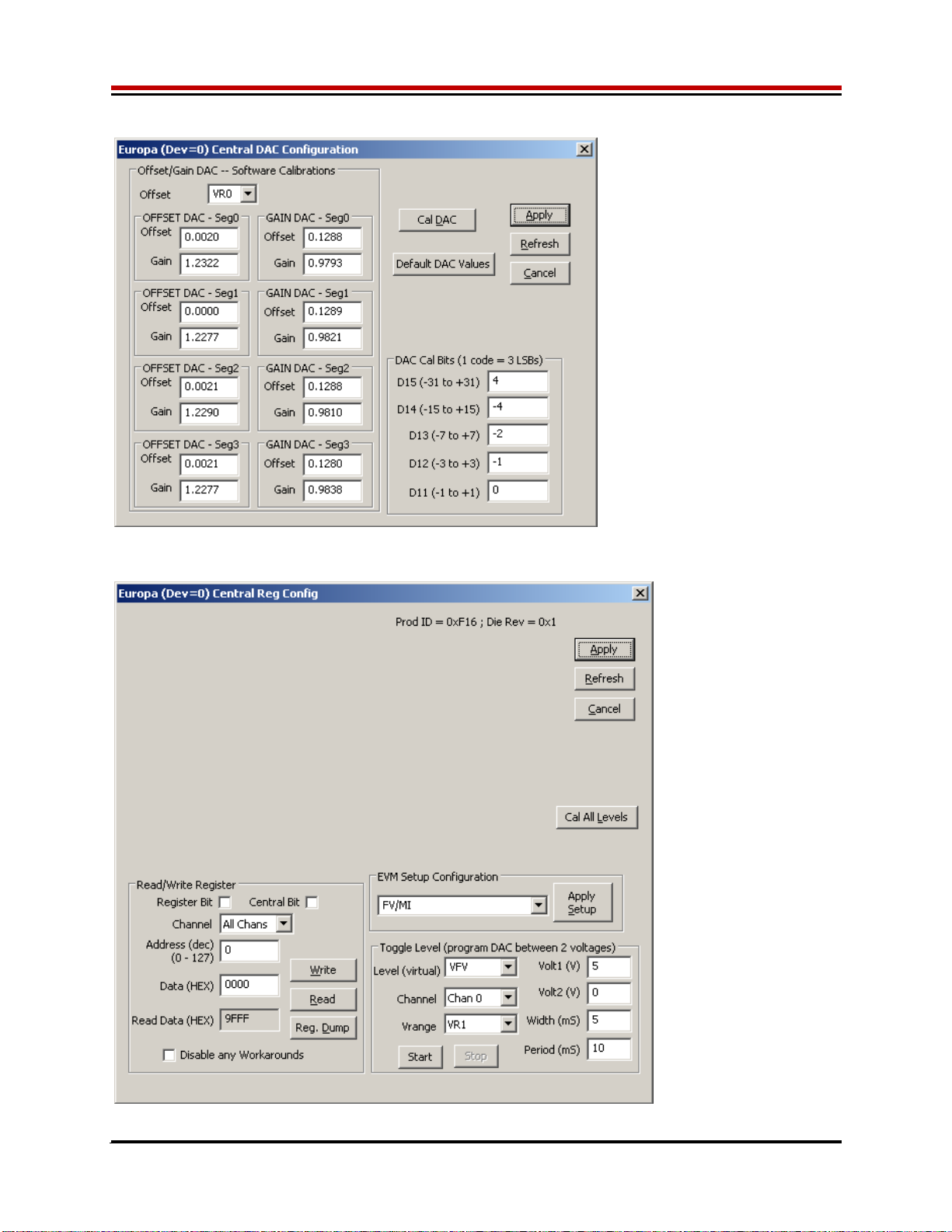
Figure 8: ISL55180 DAC Configuration Dialog Box
Figure 9: ISL55180 Central Register Dialog Box

ISL55180 EVM Getting Started Rev A04: 11/28/2012
Copyright Elevate Semiconductor Corporation 2012 Page 18 of 20
3 ISL55180 EVM Loadboard Detailed Description
Figure 10 illustrates the ISL55180 EVM EVM loadboard. Almost all of the circuitry is used to test,
validate and demonstrate in the bench. Besides decoupling caps, the only external components required
are the 10K resistor connected to REXT and the CAP_A, CAP_B, & CAP_VDD compensation caps.
Figure 10: ISL55180 EVM Detailed Block Diagram
Europa
Per-Channel (x8)
VFORCE
TEST_NODE
EVM MB
CK/SDIO/STB
RESET
3
TC26
Latch
EN EN
MONITOR
EXT_SENSE
EXT_FORCE
VREF
CH7_FORCE
TC_10/2/3
TC_4
TC15
VDD
CH3_FORCE
CH6_FORCE
A/D
VCCO_[3:0]
VEE
10K
Latch
DATA[7:0] FORCE_#
MON_REF
SMA
2-Pin Jmpr
GND
3-Pin Jmpr
Banana
LED
Symbol Legend
REXT
A/D
A/D
A/D
DATA_#
TC17/TC18
TC19/TC20
TC22/TC23
TC24/TC25 8CON_FORCE#_TN
CENTRAL_D[3:0]
EXT_MON_OE TC27
TC_32
(A/D)
GANG_IN0
GANG_IN2
GANG_IN4
GANG_IN6
TC16
E13
TJ
A/D
CH1_FORCE
CH4_FORCE
CBIT7
E2
E3
DUT_GND#
Various
Analog
Nodes 32
LB_AMUX
TC_31
(A/D)
Voltage
Divider
SENSE_# CON_SENSE#_TN
1K
VFORCE
DG#_SEL
(x8)
LB
Amux
LB
Amux
CH2_FORCE VCC
3
CAP_VDD
DAC
Latch
GANG_OUT1
TC_9 (LB Amux)
On MB
TC_8 (LB Amux)
On MB
TC_6 (LB Amux)
On MB
TC_5 (LB Amux)
On MB
GANG_OUT7
GANG_OUT5
GANG_OUT3
CON_ES_TN
CAP_A#
CAP_B#
CON_EF_TN
E20
MI_MON
A/D
A/D
A/D
OT*
TC14
ALARM*
TC13
TEST+
TEST-
CH5_FORCE VOH_SDIO
Amux
Amux
1K
CON_MI_MON_TN
CON_MONITOR_TN
VFORCE
GANG#_SEL
(x4)
Single-Ended
to Differential
Div
Div
VFORCE
CH7_FORCE
TEST_NODE
1.65V TEST_SEL
TC28
CENT_SEL
(x4)
TC15
VREF_SEL
REXT_SEL
TEST_NODE
TEST_NODE
A/D
A/D
CON_MON_REF_TN
Switcher
ISL8540
VCCO_[7:4]
Switcher
ISL8540
External
Power
Supply
V+
V-
Clock
Divider
TC29
TC30
PLL_CK
on MB SYNC
ISL55180 EVM Getting Started Rev A04: 11/28/2012
Copyright Elevate Semiconductor Corporation 2012 Page 19 of 20
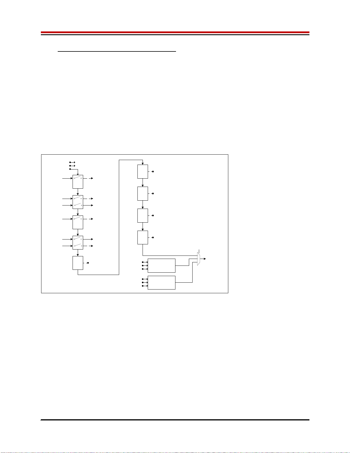
3.1 ISL55180 EVM Loadboard Controller
Figure 11 illustrates the ISL55180 EVM controller section. The ISL55180 EVM loadboard contains nine
8-bit latches (registers), a 16K EEPROM, and a Digitally Controlled Potentiometer (DCP). The Cbit1 to
CBit7 are also used to control various relays, the C-Bit# are open-drain outputs used to control relays.
The C-Bits originate from the Octal FVMI board.
The latches are daisy chained together using the SDI_SCK/RCK/CS signals originating from the
Motherboard. The EEPROM is controlled by the LPORT1_OUT[4:2] signals originating from the
motherboard. The DCP is controlled by LPORT1_OUT4/2 and LB_DATA3 signals originating from the
motherboard.
The loadboard latches are labeled STB_I to STB_Q. This was named as an extension to the REG_A to
REG_H Octal FVMI / Motherboard registers.
Figure 11: Controller Section Detailed Block Diagram
EEPROM
1K x 16-Bit
Latch
N8DUTGND#_SEL (8)
Latch
O8
LB_AMUX (4)
GANG_IN_SEL
DUTGND_SEL
REXT_SEL
VREF_SEL
Latch
P8
LB_AMUX_EN0
RDB_SEL[2:0] (3)
FSEL (3)
Unused
Switch I
GND 8CON_FORCE#_TN
Switch J
GND 7
LPORT1_OUT3 CLK
CS
DIN
LPORT1_OUT2
LPORT1_OUT4
EEPROM_DO
LPORT1_OUT3 SCK
RCK / CS
TC_21
Latch
Q
RB_SER_DO
LPORT3_IN2
(to PC)
RDB_SEL[2:0]
DOUT
Unused (6)
CON_EF_TN
8
GANG#_SEL (4)
TESTP_SEL
TESTN_SEL
Unused (2)
LPORT1_OUT4
TEST_NODE CON_ES_TN
Latch
M8CENT_[D:A]_SEL (4)
CENT_D[3:0] (4)
Switch
K
8CON_SENSE#_TNTEST_NODE
Switch L
GND
CON_MON_REF_TN
CON_MONITOR_TN
CON_MI_MON_TN
TEST_NODE
5Unused (5)
DCP
LPORT1_OUT3 CLK
CS*
DIN
CBIT3
LPORT1_OUT4
DOUT
DCP_DO
Only showing Europa /Switcher loadboard mapping

ISL55180 EVM Getting Started Rev A04: 11/28/2012
Copyright Elevate Semiconductor Corporation 2012 Page 20 of 20
4 Document Revision History
Revision Date Description
A04 6/18/12 Updated several figures.
A03 2/27/12 Updated document.
A02 1/27/10 Add loadboard changes and switcher section
A01 9/24/09 Initial Draft. ISL55180 R1 and Europa/Switcher Rev A support
Table of contents
Other ELEVATE Motherboard manuals


Popular Motherboard manuals by other brands


Microchip Technology
Microchip Technology HV2916 user guide

Texas Instruments
Texas Instruments ADC-PHI-PRU-EVM user guide

Select Engineered Systems
Select Engineered Systems SAT3 user guide

ASROCK
ASROCK H87E-ITX/ac Quick installation guide

Texas Instruments
Texas Instruments ISO1644DWEVM user guide

ST
ST STEVAL-SPIN3202 user manual