Name Pin Label Description
TP15 - TP15 Output op amp sense 3
TP16 - CLK SWD_CLK
TP17 - I/O SWD_IO
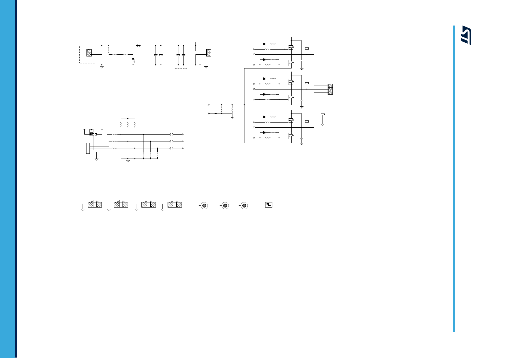
2.2 Circuit description
The STEVAL-SPIN3202 evaluation board provides a complete single-shunt six-step solution consisting of an
STSPIN32F0A advanced BLDC controller with an embedded STM32 MCU and a triple half-bridge power stage
with the STD140N6F7 NMOS.
The STSPIN32F0A autonomously generates all the required supply voltages starting from the motor supply: the
internal DC/DC buck converter provides 3.3 V and the internal linear regulator provides 12 V for the gate drivers.
The current feedback signal conditioning is performed through the operational amplifiers embedded in the device
and an internal comparator performs overcurrent protection via the shunt resistor.
Two user buttons, two LEDs and a trimmer are available to implement simple user interfaces (e.g., starting/
stopping the motor and set target speed).
The STEVAL-SPIN3202 evaluation board supports the quadrature encoder and digital Hall sensors for motor
position feedback. It also provides the circuitry to sense the motor BEMF (sensorless operation).
The board includes an ST-LINK/V2 which allows the user to debug and download firmware without additional
hardware.
The board also supports sensored or sensorless field oriented control algorithm with single-shunt sensing.
2.2.1 Six-step/FOC selection
The user can select between six-step and field oriented control modes by selecting different jumpers on the
STEVAL-SPIN3202 evaluation board.
By default, the six-step mode is selected as per the following configuration:
• jumper connected on J12 open and jumper J11 closed;
• jumper connected on JP8 between pin 1 and 2 (six-step position).
The field oriented control mode is selected as follows:
• jumper connected on J12 closed and remove jumper from J11;
• jumper connected on JP8 between pin 2 and 3 (FOC position).
2.2.2 Hall/encoder motor speed sensor
The STEVAL-SPIN3202 evaluation board supports the digital Hall and quadrature encoder sensors as motor
position feedback.
The sensors can be connected to the STSPIN32F0A by closing jumpers JP5, JP6 and JP7 (open by default).
Note: When JP5, JP6 and JP7 are closed (Hall/encoder mode), JP9, JP10 and JP11should be respectively open
(BEMF sensing mode).
The Hall sensor/encoder should be connected to J4 as per the following table.
Table 3. Hall/encoder connector (J4)
Name Pin Description
Hall1/A+ 1 Hall sensor 1/encoder out A+
Hall2/B+ 2 Hall sensor 2/encoder out B+
Hall3/Z+ 3 Hall sensor 3/encoder zero feedback
VDD sensor 4 Sensor supply voltage
GND 5 Ground
A protection resistor of 1 kΩ is mounted in series with the sensor outputs.
UM2278
Circuit description
UM2278 - Rev 2 page 5/17