ELEVATE Jupiter User manual

Jupiter EVM Getting Started Rev C01 : 05/17/2007
Copyright Elevate Semiconductor 2012 Page 1 of 22
Jupiter EVM Getting Started
Rev C01 : 05/17/2007
.

Jupiter EVM Getting Started Rev C01 : 05/17/2007
Copyright Elevate Semiconductor 2012 Page 2 of 22
Table of Contents
1Introduction..........................................................................................................................................................4
1.1 Unpacking - Jupiter EVM Contents ..........................................................................................................4
1.2 Recommended Test and Measurement Setup...........................................................................................5
1.2.1 Power Supply.........................................................................................................................................5
1.2.2 PC Controller.........................................................................................................................................5
1.2.3 DMM or Source Measurement Unit ......................................................................................................5
1.3 Software Installation ...................................................................................................................................6
1.3.1 Jupiter EVM UIP Installation ................................................................................................................6
1.3.2 Parallel Port (ParPort2K) Installation....................................................................................................6
1.3.3 Reboot Machine.....................................................................................................................................6
1.3.4 Launching the Elevate Semiconductor Program....................................................................................6
1.3.5 Software Un-Installation........................................................................................................................6
2Getting Started......................................................................................................................................................7
2.1 Caution .........................................................................................................................................................7
2.2 Jupiter Loadboard Rev B versus Rev C+..................................................................................................7
2.3 Quick Start Instructions..............................................................................................................................7
2.4 Default Configuration Setup Options ........................................................................................................9
2.4.1 Remote Sense Option...........................................................................................................................10
2.4.2 General DPS Configurations................................................................................................................10
2.4.3 Ganging (Merging) Configuration.......................................................................................................11
2.5 Jupiter Loadboard Jumper Definitions...................................................................................................12
2.6 Motherboard Jumper and SMA Definition.............................................................................................13
2.7 Jupiter EVM Menu and Dialog Boxes.....................................................................................................14
3Jupiter EVM Loadboard Detailed Description..................................................................................................18
3.1 Capacitor and Resistor Network Definitions...........................................................................................19
3.2 ADC and Analog Mux...............................................................................................................................20
3.3 Jupiter Loadboard Controller..................................................................................................................21
4Document Revision History................................................................................................................................22

Jupiter EVM Getting Started Rev C01 : 05/17/2007
Copyright Elevate Semiconductor 2012 Page 3 of 22
List of Figures
Figure 1: Installation Directory Structure......................................................................................................6
Figure 2: Expected Current Readings..........................................................................................................8
Figure 3: Jupiter EVM Simplified Block Diagram.......................................................................................10
Figure 4: Jupiter EVM Ganging Configuration Simplified Block Diagram..................................................11
Figure 5: Device Config Menu Options......................................................................................................14
Figure 6: Jupiter Configuration Dialog Box................................................................................................15
Figure 7: Jupiter DC Levels Dialog Box.....................................................................................................16
Figure 8: Jupiter DAC Configuration Dialog Box .......................................................................................16
Figure 9: Jupiter Central Register Dialog Box............................................................................................17
Figure 10: Jupiter EVM Detailed Block Diagram........................................................................................18
Figure 11: Jupiter EVM Capacitor/Resistor Network Block Diagram.........................................................19
Figure 12: Controller Section Detailed Block Diagram ..............................................................................21
List of Tables
Table 1: Jupiter EVM Contents.....................................................................................................................4
Table 2: Power Supply Requirements .........................................................................................................5
Table 3: Jupiter Default Configuration Options............................................................................................9
Table 4: Jupiter Loadboard Jumper Definitions.........................................................................................12
Table 5: Motherboard SMA and Jumper Definitions (Jupiter Input Signals)..............................................13
Table 6: Motherboard SMA Definitions (Jupiter Output Signals)...............................................................13
Table 7: Capacitor Network Definitions......................................................................................................19
Table 8: Resistor Network Definitions........................................................................................................19
Table 9: FVMI Analog Mux – VINPOS(A) & VINNEG(A) Mapping.............................................................20
Table 10: Jupiter Loadboard Analog Mux Definitions - LB_AMUX Mapping.............................................20

Jupiter EVM Getting Started Rev C01 : 05/17/2007
Copyright Elevate Semiconductor 2012 Page 4 of 22
1 Introduction
Congratulations on your purchase of a Elevate Semiconductor Jupiter EVM evaluation system. You will
find that it serves as an invaluable development platform to help get your product to market in the shortest
possible time. The Jupiter EVM and Graphical User Interface (GUI) allow the customer to demonstrate
and evaluate the Jupiter performance and functionality.
This document provides the instructions to install, setup, and operate the Jupiter EVM. Refer to the
Elevate Semiconductor EVM User’s Guide for a detailed description of the EVM system.
1.1 Unpacking - Jupiter EVM Contents
Please check the contents of the Jupiter EVM shipping carton to make sure you have received all of the
items listed in Table 1. The system is already configured for the best setup, except for connections to the
power supply, PC controller, and test equipment.
Table 1: Jupiter EVM Contents
Qty Description
1 ea. Jupiter EVM System (3 boards)
1 ea. Jupiter EVM Getting Started (this document)
1 ea. CD Contents List
1 ea. Elevate Semiconductor User Interface Program Installation CD
1 ea. DB25M-DB25M, 6 Foot Parallel Port Cable

Jupiter EVM Getting Started Rev C01 : 05/17/2007
Copyright Elevate Semiconductor 2012 Page 5 of 22
1.2 Recommended Test and Measurement Setup
1.2.1 Power Supply
Table 2 provides the required power supplies and current rating. The power supplies are connected
using standard banana plugs. The customer needs to provide the power supply cables.
It is recommended to use a triple supply to control the EVM supplies. This allows the 3 EVM supplies to
be turned on at the same time. However, if this is not feasible, then the supplies should be enabled in the
following sequence. Power down should be performed in the reverse order.
1. +20V
2. -15V
3. +5V
The Jupiter VCC, VCC_OUT and VEE are gated using an Opto-FET switch on the loadboard so it is safe
to set and enable the Jupiter supplies before powering up the EVM and running the software.
Table 2: Power Supply Requirements
Module Supply Current Rating
Motherboard +20V
(1)
0.5 A
Motherboard +5V 0.5 A
Motherboard -15V 0.5 A
Jupiter VCC/VCC_OUT +16V
(
2
,
3
)
2.0 A
(
4
)
Jupiter VEE -5V
(
2
,
3
)
2.0 A
(
4
)
Notes:
1) The EVM +20V could also be used as the Jupiter VCC
2) Once the EVM operation is verified, the customer can adjust the VCC, VCCO, VEE supplies
3) The Jupiter VCC – VEE voltage should not exceed 34V. Refer to the ABS max section in the
datasheet.
4) The VCC, VCC_OUT, and VEE current requirements are assuming a Master and Slave device is
present. If only the Master is present, then a 1 Amp supply is adequate. The program does not
have the ability to measure the Jupiter VCC and VEE currents
1.2.2 PC Controller
To use the Jupiter EVM User Interface Program (UIP), a PC with the following configuration is required:
Win98, Win2000, WinNT 4.0+, or Win XP
Parallel/Printer Port – 25-pin female connector (a parallel port cable is provided)
1.2.3 DMM or Source Measurement Unit
Voltage and/or Current Meter
Voltage and/or Current Source

Jupiter EVM Getting Started Rev C01 : 05/17/2007
Copyright Elevate Semiconductor 2012 Page 6 of 22
1.3 Software Installation
There are 2 steps to install the Jupiter EVM demonstration program.
1. Install the Jupiter EVM UIP from the CD-ROM.
2. Install the parallel port driver (ParPort2k).
Figure 1 illustrates the default directory structure. The user may change the <root dir> during the
installation.
Figure 1: Installation Directory Structure
<Root Dir>\Planet ATE\EVM\Documents (several folders)
EVM GUI
ParPort2k
1.3.1 Jupiter EVM UIP Installation
To install the Jupiter EVM software package, run the SETUP program on the distribution CD and follow
the prompts. The PlanetATE.exe executable will be installed in the EVM GUI sub-directory. In addition,
a short cut will be installed onto the desktop and in the Start->Programs folder. The Start->Programs
folder also contains links to the different product datasheets, EVM User’s Guide, and documentation
folder.
1.3.2 Parallel Port (ParPort2K) Installation
To install the ParPort2K parallel port driver, run the setup.exe from the ParPort2k sub-directory after the
main installation is complete and click the Install button. For WinNT users, the user must have
administration rights.
Note: ParPort2k is a copyright of Zeecube Software.
1.3.3 Reboot Machine
After the Jupiter EVM and Parallel Port software is installed, it is recommended to re-boot the machine.
1.3.4 Launching the Elevate Semiconductor Program
The user can launch the Elevate Semiconductor GUI from the Desktop, Start->Programs folder, or
EVM GUI sub-directory.
1.3.5 Software Un-Installation
The Elevate Semiconductor demonstration program may be un-installed using the Add/Remove
Program from the Windows Control Panel.

Jupiter EVM Getting Started Rev C01 : 05/17/2007
Copyright Elevate Semiconductor 2012 Page 7 of 22
2 Getting Started
The Jupiter EVM is shipped in a pre-configured state that allows a customer to evaluate the DPS Force
Voltage (FV), Force Current (FI), and Ganging.
Note: Any external equipment providing digital signals into the Jupiter device should only be enabled
after the Jupiter EVM is enabled. Also, the external equipment should be disabled prior to disabling the
Jupiter EVM.
2.1 Caution
Jupiter is a high voltage DUT Power Supply (DPS) capable of delivering several amps of current.
Configuring the Jupiter device and EVM into an extremely high power condition could cause permanent
damage to the Jupiter device, EVM components and/or external equipment.
2.2 Jupiter Loadboard Rev B versus Rev C+
There are 2 different loadboard revisions; Rev B and Rev C+. This document focuses on the Rev C+
loadboard; refer to Section 3 for details. Refer to previous document revisions when using the Rev B
loadboard. The software supports both loadboard revisions.
2.3 Quick Start Instructions
1. Disable external power supply
2. Connect the power supplies cables (not provided) from the power supply to the Elevate
Semiconductor EVM Motherboard and Jupiter loadboard; refer to Figure 3.
3. Connect the parallel cable (provided) from the PC to J2 on the Octal FVMI board.
4. Connect the EVM to any external equipment; refer to Section 2.4.
5. Setup Motherboard Jumpers; refer to Section 2.5
6. Set external power supply voltages and current limits.
7. Enable external power supply.
8. Run the Elevate Semiconductor GUI software; refer to Section 1.3.4 for details.
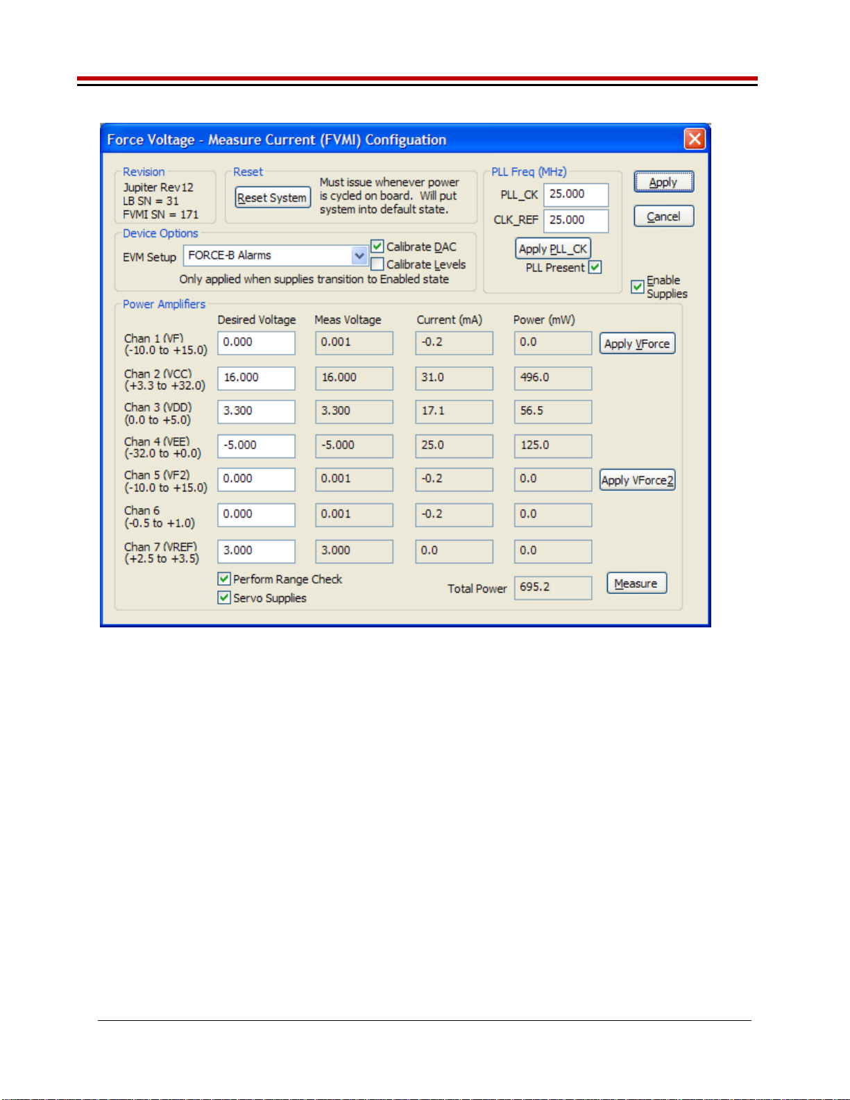
9. At the Force Voltage – Measure Current dialog box (refer to Figure 2 below):
a. Select the EVM Setup option based on the desired configuration, see Section 2.4
b. Select the Enable Supplies check box
c. Hit the Apply button to power up the Jupiter device.
d. The software will also measure the current consumption. Figure 2 illustrates the expected
current readings.
10. At this point, the Jupiter should be outputting the desired signal.
Jupiter EVM Getting Started Rev C01 : 05/17/2007
Copyright Elevate Semiconductor 2012 Page 8 of 22
Figure 2: Expected Current Readings
The Reset System will put the EVM and Jupiter device into the default state. The Reset System should
be issued whenever the power supply is powered OFF then ON. The Reset System is automatically
performed when the program is initially launched.

Jupiter EVM Getting Started Rev C01 : 05/17/2007
Copyright Elevate Semiconductor 2012 Page 9 of 22
2.4 Default Configuration Setup Options
The EVM has several default options for configuring for device and loadboard.
Table 3: Jupiter Default Configuration Options
Mode See Section # Brief Description
Hardware Reset N/A All registers default to the hardware default state.
Note: Output is always present on FORCE_A. Sel-Force=GND
Three-State (High-Z) N/A Puts DPS in three-state (high-Z). Opens all switches.
Note: Output is always present on FORCE_A. Sel-Force=GND
FV out FORCE-A
with Alarms 2.4.2 FV mode with Alarms enabled. Connect DPS output to
TEST_NODE via FORCE_A. VF0= 3.0V.
FV out FORCE-B
with Alarms 2.4.2
(default) FV mode with Alarms enabled. Connect DPS output to
TEST_NODE via FORCE_B. VF0= 3.0V.
Note: Output is always present on FORCE_A.
Ganging 2.4.3 Master (U1) placed into FV mode with Remote Sense.
Slave (U2) placed into FI mode using Master’s MI as reference.
Master/Slave use FORCE-B output connected to TEST_NODE.
Alarms are enabled. IR=512mA.
External DAC
(FV Mode) 2.4.2 Bypass the internal DAC and use the FVMI resources as inputs
into Gang2/Gang3. FV mode with Alarms enabled. Connect
DPS output to TEST_NODE via FORCE_B.
VFORCE2=1.5V, VFORCE=0V
Default: applies to all software configurations
Loadboard: Jumpers E2, E4, and E7 are installed
Jupiter: CPU-En = 1 and Local-Sense* = 1
Jupiter: Monitor Enabled, Sel-MV = MV
Jupiter: Iclamps = +/-700mA. Vclamps = 14V/-2V (but disabled)
Jupiter: COMP_A, COMP_B, and External CAP_SR connected and SR-Adj = 15
FORCE-A default configuration
Loadboard: FORCE_A is connected to TEST_NODE (Con-FA-TN)
Loadboard: SENSE pin is connected to TEST_NODE (Con-Sense-TN)
Jupiter: Sel-FB (feedback) = FORCE_A
Jupiter: Con-FA-FB switch = open
FORCE-B default configuration
Loadboard: FORCE_B is connected to TEST_NODE (Con-FB-TN)
Loadboard: SENSE pin is connected to TEST_NODE (Con-Sense-TN)
Jupiter: Sel-FB (feedback) = FORCE_B
Jupiter: Con-FA-FB switch = closed
FORCE-A/B with Alarms configuration
The device is configured to automatically shut down if an Over Temperature alarm fault is detected
Over Tempature enabled and set to code=4 (approximately 116’C)
IClamp Alarm enabled but not routed to Global Alarm (won’t shut down DPS)
Sel-Con-FA-FB = 1 (use On-Chip-En)
Sel-DPS-En = 1 (use Global-Alarm)
For FORCE-A, the DPS_EN is used to control the FORCE_A to TEST_NODE relay
Note: the alarms are setup to latch the fault condition. To remove the fault, issue the appropriate ‘reset’
in the Jupiter Configuration dialog box. Use the LEDs or ReadBack to determine which alarm tripped.

Jupiter EVM Getting Started Rev C01 : 05/17/2007
Copyright Elevate Semiconductor 2012 Page 10 of 22
2.4.1 Remote Sense Option
Extreme caution should be used when configuring the feedback (SENSE) path to ensure the DPS does
not become open loop. The Jupiter device has 2 output pin options (FORCE-A or FORCE-B) and internal
mux options. The Loadboard has several jumper and switch options to directly connect to the
FORCE-A/B pin or to connect to the TEST_NODE.
Note: To put the Jupiter device in remote sense, after selecting the FORCE-A or FORCE-B configuration
option then change the ‘CPU-Sel-FB’ option to SENSE
2.4.2 General DPS Configurations
Figure 3 illustrates the recommended configuration for Jupiter EVM evaluation. After the configuration is
completed, use the Jupiter->DPS Levels dialog box the change the Jupiter output levels. Use the
Jupiter Loadboard dialog box to connect to the on-board resistor network and/or capacitive load.
For the External DAC mode, jumper E1 must be installed. The VFORCE2 voltage is connected to the
Gang2 (V+) input and the VFORCE voltage is connected to the Gang3 (V-) input. Use the
EVM->FVMI (DPS) Config dialog box to change the VFORCE and VFORCE2 voltage values.
If using an external measurement unit (MU), the MU should be configured in the opposite mode as
Jupiter.
Jupiter MU
FVMI FIMV
FIMV FVMI
Important note: the FORCE_A is always connected to the high power op-amp stage and can not be put
into HiZ (disabled). Therefore when using the FORCE_A option, it is recommended to connect any load
to the TEST_NODE SMA so the Con-FA-TN relay can be opened in the event of an alarm condition.
Figure 3: Jupiter EVM Simplified Block Diagram
Motherboard
Jupiter Load Board
PC
J2 (FVMI)
Parallel
Cable
EVM
Power
Supply
Jupiter
DMM
or
Measurement
Unit
MONITOR
MONITOR
FORCE_A
SENSE
FORCE_A
VCC
VCCOUT
VEE
+20V (BN1)
-15V (BN2)
+5V (BN3)
GND (BN4) LEDs
FORCE_B
SENSE
FORCE_B
TEST_NODE
Rnet
Cloads
DPS_EN
Jupiter
Power
Supply
E1 (VFORCE)

Jupiter EVM Getting Started Rev C01 : 05/17/2007
Copyright Elevate Semiconductor 2012 Page 11 of 22
2.4.3 Ganging (Merging) Configuration
Figure 4 illustrates the recommended configuration for the ganging application. The Master (U1) is
configured in FV mode in Remote Sense while the Slave (U2) is configured in FI mode. The Master and
Slave both use the FORCE_B output pin which allows for internal alarm shut down. The Master and
Slave are connected to the TEST_NODE SMA via the loadboard relays and 2-pin jumpers (E7 for Master
and E5 for Slave). The E4 jumper must also be installed which provides the SENSE return path. The
GANG_0 node is used to provide the Master MI signal to the Slave device.
The loadboard SLAVE_EN (CBit4) control bit is used to completely isolate and/or connect the Slave
device supplies. The Slave device has the VCC and VCCO power pins tied together therefore the user
should tie the Master (main) VCC and VCCOUT together. The Slave shares the Master’s CPU_CK and
SDIO signals while the Master and Slave have dedicated STB and RESET signals. The Slave’s input
signals are tied low so there is no real-time control. The Slave’s Alarm is connected to an LED. The
Slave’s CBit outputs are not connected. The Slave’s MONITOR and TJ pins are accessible by the A/D
on the FVMI board; these results can be found in the EVM Config->FVMI Measure dialog box.
Note: The hardware supports Ganging via the FORCE_A pins; however, the software does not have a
default configuration for using FORCE_A.
Figure 4: Jupiter EVM Ganging Configuration Simplified Block Diagram
Motherboard
Jupiter Load Board
PC
J2 (FVMI)
Parallel
Cable
EVM
Power
Supply
Master
(U1)
DMM
or
Measurement
Unit
MONITOR
MONITOR
E4
SENSE
VCC
VCCOUT
VEE
+20V (BN1)
-15V (BN2)
+5V (BN3)
GND (BN4) LEDs
FORCE_B
E7
SENSE
FORCE_B
TEST_NODE
Rnet
Cloads
GANG0
Slave
(U2)
MONITOR
SENSE
FORCE_B
GANG0
E5
GANG_0
FORCE_A
Jupiter
Power
Supply

Jupiter EVM Getting Started Rev C01 : 05/17/2007
Copyright Elevate Semiconductor 2012 Page 12 of 22
2.5 Jupiter Loadboard Jumper Definitions
Table 5 lists the Jupiter Loadboard Jumper definitions. These jumpers provide different remote sense
options, the ability to isolate analog pins for low current leakage measurements, and other test options.
Important Note: Extreme caution should be used when configuring for different feedback options. Always
ensure there is a proper feedback so the DPS op-amp isn’t open loop.
Table 4: Jupiter Loadboard Jumper Definitions
Jumper Description Default Configuration
E1 Connect VFORCE Installed (for ExtDAC)
E2 FORCE_A to TEST_NODE Installed
E3 FORCE_A to SENSE Open
E4 SENSE to TEST_NODE Installed
E5 Slave FORCE_B to TEST_NODE Installed (for Ganging)
E7 FORCE_B to TEST_NODE Installed
E8 FORCE_B to SENSE Open
E9 Use DPS_EN to control FORCE_A select switch Installed
E10 Use EVM Latch to control FORCE_A select switch Open
E11 Slave FORCE_A to TEST_NODE Open
E12 Fan PWR TBD
E13 Fan PWR TBD

Jupiter EVM Getting Started Rev C01 : 05/17/2007
Copyright Elevate Semiconductor 2012 Page 13 of 22
2.6 Motherboard Jumper and SMA Definition
Table 5 lists the Motherboard Jumper/SMA definitions for the Jupiter EVM. Only the EN (E3) jumper/SMA
would be optionally used by a customer. The other jumpers must be shorted between pin 1&2 (towards
back of board) to ensure proper operation.
Table 5: Motherboard SMA and Jumper Definitions (Jupiter Input Signals)
TC# Jumper Usage Configuration
TC30 E12 Reserved Short Pin 1 & 2. towards back of board
TC29 E11 Reserved Short Pin 1 & 2. towards back of board
TC28 E14 SDI_DATA Short Pin 1 & 2. towards back of board
TC27 E15 SDI_SCK Short Pin 1 & 2. towards back of board
TC26 E2 SDI_RCK Short Pin 1 & 2. towards back of board
TC25 E10 Slave RESET Short Pin 1 & 2. towards back of board
TC24 E9 Slave STB Short Pin 1 & 2. towards back of board
TC23 E8 EXT_MON_OE Short Pin 1 & 2. towards back of board
TC22 E7 Unused Short Pin 1 & 2. towards back of board
TC21 E1 EXT_TJ_EN Short Pin 1 & 2. towards back of board
TC20 E6 EXT_LD Short Pin 1 & 2. towards back of board
TC19 E5 EXT_UD Short Pin 1 & 2. towards back of board
TC18 E4 EXT_ADDR_CK Short Pin 1 & 2. towards back of board
TC17 E3 EN Short Pin 1 & 2: source from latch
Short Pin 2 & 3: source from SMA
TC16 E13 N/A Don’t care
TC15 E20 N/A Don’t care
The following table defines the Jupiter output signals. These are always present at the motherboard
SMAs.
Table 6: Motherboard SMA Definitions (Jupiter Output Signals)
TC# MB EVM
TC14 KEL_ALARM_N
TC13 V_ALARM_N
TC12 I_ALARM_N
TC11 OT_ALARM_N
TC9 ALARM_N
TC8 C_BIT_N
TC6 CAP_DIS_N
TC5 DPS_EN_N
Jupiter EVM Getting Started Rev C01 : 05/17/2007
Copyright Elevate Semiconductor 2012 Page 14 of 22
2.7 Jupiter EVM Menu and Dialog Boxes
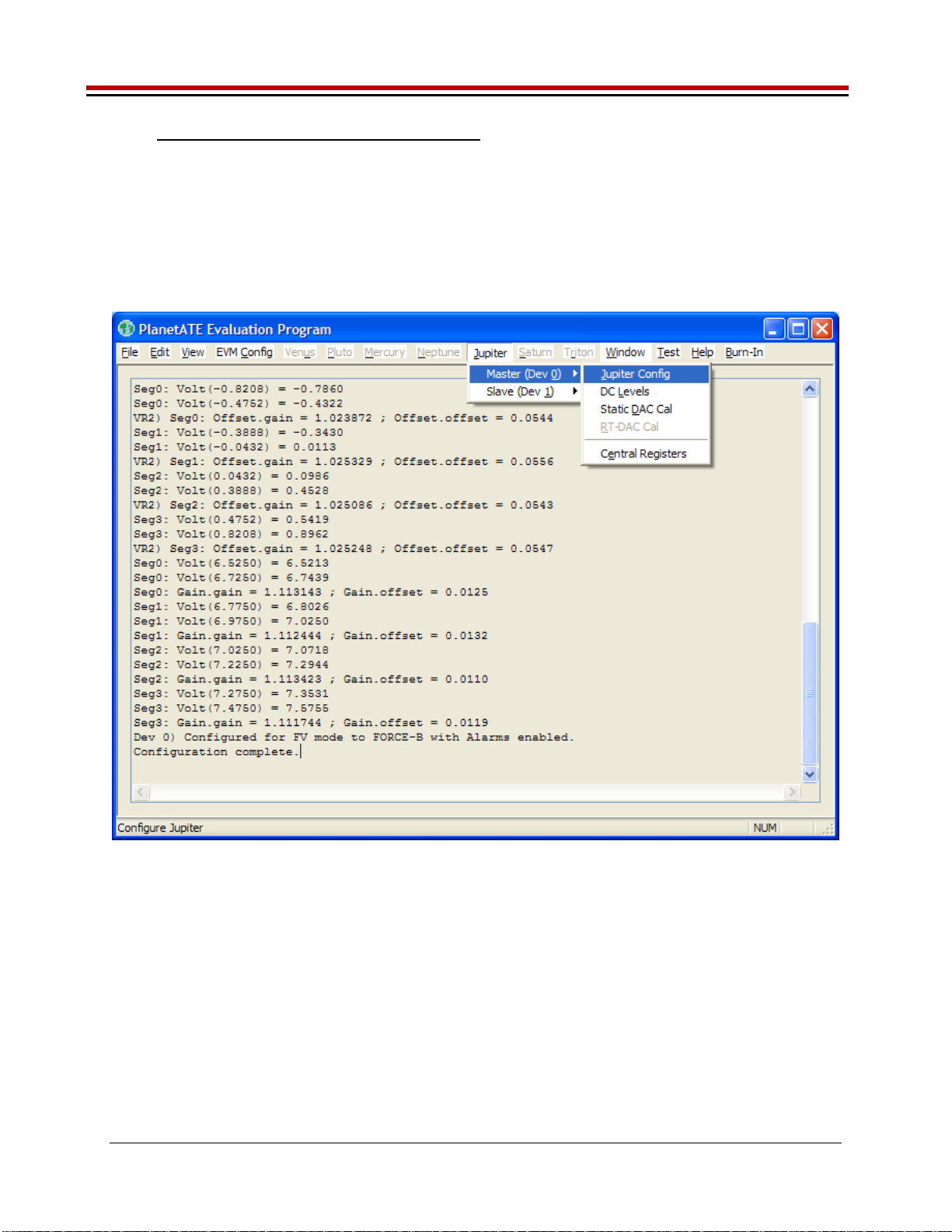
Figure 5 illustrates the Jupiter EVM menu options that provide access to the Jupiter dialog boxes. For
each Jupiter register, there is a control field allowing the customer to have full control over the Jupiter
device. These screen shots show the default ‘FV out FORCE-B with Alarms’ configuration.
There are separate menu and dialog boxes for the Master and Slave device. The Slave dialog boxes are
only available if the Slave is detected.
Figure 5: Device Config Menu Options
Jupiter EVM Getting Started Rev C01 : 05/17/2007
Copyright Elevate Semiconductor 2012 Page 15 of 22
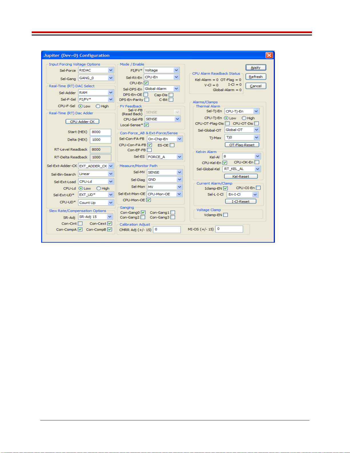
Figure 6: Jupiter Configuration Dialog Box
Jupiter EVM Getting Started Rev C01 : 05/17/2007
Copyright Elevate Semiconductor 2012 Page 16 of 22
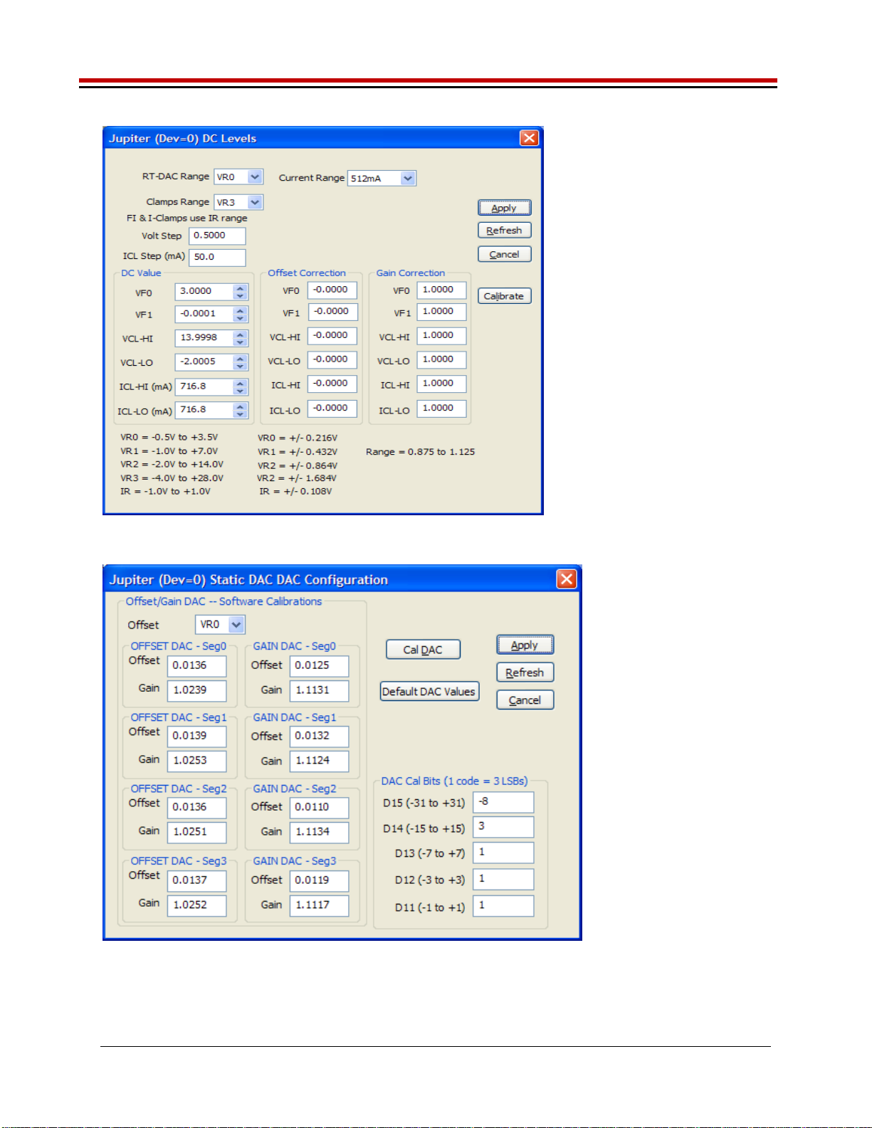
Figure 7: Jupiter DC Levels Dialog Box
Figure 8: Jupiter DAC Configuration Dialog Box

Jupiter EVM Getting Started Rev C01 : 05/17/2007
Copyright Elevate Semiconductor 2012 Page 17 of 22
Figure 9: Jupiter Central Register Dialog Box
Jupiter EVM Getting Started Rev C01 : 05/17/2007
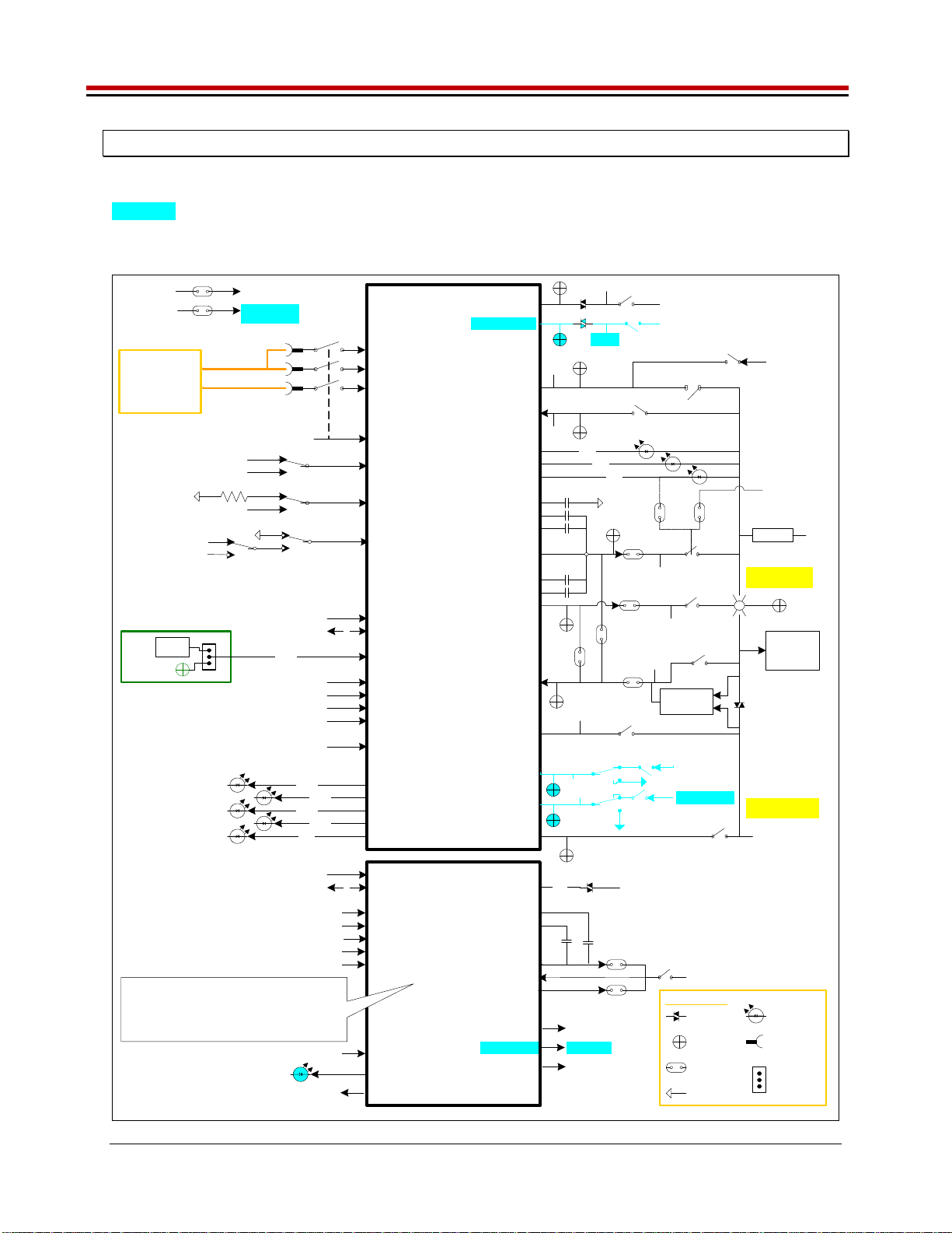
Copyright Elevate Semiconductor 2012 Page 18 of 22
3 Jupiter EVM Loadboard Detailed Description
Figure 10 illustrates the Jupiter EVM loadboard. The loadboard contains the Jupiter device as well as the
necessary circuitry to validate & characterize on the bench environment. Circuitry highlighted in
turquoise is new or modified on the Rev C loadboard.
Figure 10: Jupiter EVM Detailed Block Diagram
TC5
VFORCE
TESTNODE
MB
Jupiter
(Master)
CLK/SDIO/STB
RESET
3
E2
TC17
Latch
TC_17
EN
FORCE_A
SENSE
Resistor
Network
CON_ES_TN
CON_VFORCE_EF
VFORCE
CON_EF_TN
MONITOR
EXT_SENSE
EXT_FORCE
TestNode(p)
VREF
VREF_SEL
VREF (DPS)
TestNode(p)
TC_10/2/3
TC_4
DUT_GND
TestNode(p)
GANG[1:0]
CON_GANG[1:0]_TN
VDD
CH3_FORCE
CH1_FORCE A/D CON _MON _TN
EXT_MON_OE
TC23
VFORCE
DUT_GND_SEL
VCC
External
Power
Supply
VCCOUT
VEE
V+
V-
EXT_ADDR_CKTC18
EXT_U/D*
TC19
A/D
E4
FORCE_B
CON_SENSE_TN
CON_FB_TN
CAP_BP
CAP_AP
E3
E8
TESTNODE(p)
A/D
DPS_EN*
TC6
CAP_DIS*
TC8C_BIT
Tj
CON_TJ_TN
A/D
Jupiter
(Slave)
CLK/SDIO/STB
RESET
3
TC_10/2/24
TC_25
VCC / VCCOUT
VEE
VDD
VCC
VEE
VDD
DUT_GND
GND
VREF
VREF
GANG[3:0] (4)
E11
FORCE_A
SENSE
CON_SLAVE_TN
E5
FORCE_B
CAP_A/BP
CAP_A/BN
x2 x2
TEST_NODE
All Slave (Gang) supplies and input/output signals are
isolated from the Master via a switch , channel
protector, and/or use a dedicated control signal .
Use SLAVE_EN (CBit4) to enable the switches.
Digital Inputs
GND
Digital Outputs
N/C
MONITOR A/D
Tj A/D
A/D
A/D
A/D
REXT
REXT_SEL
TestNode(p)
10K
EXT_LDTC20
EXT_TJ_EN
TC21
ALARM*TC9
I_ALARM*TC12
KEL_ALARM*TC14
OT_ALARM*TC11
V_ALARM*TC13
CAP_SR
CAP_AN
CAN_BN
E7
Capacitor
Network
E10E9
CON_FA_TN
Div2 A/D
GANG2 VFORCE2
GANG0
A/D
Channel
Protector
SMA
2-Pin Jmpr
GND
3-Pin Jmpr
Banana
Jack
LED
Symbol Legend
ALARM*
MON_REF A/D
MON_REF TestNode(p)
A/D CON _MON_REF_TN
GANG3_SEL
GANG3 VFORCE
VFORCE2
CH5_FORCE
A/D
A/D
CON_GANG3_VF
CON_GANG2_VF2
GANG[3:0]
(Master)
GANG2_SEL
Jupiter EVM Getting Started Rev C01 : 05/17/2007
Copyright Elevate Semiconductor 2012 Page 19 of 22
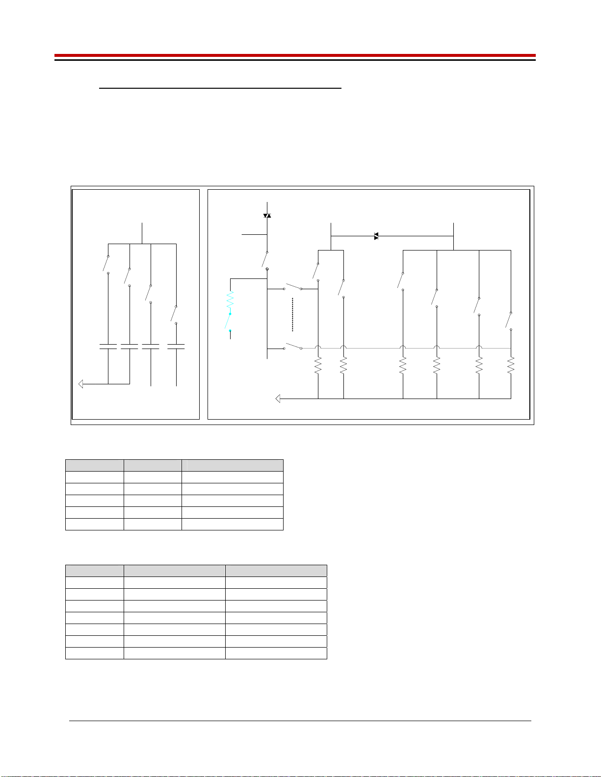
3.1 Capacitor and Resistor Network Definitions
Figure 11 illustrates while Table 7 and Table 8 list the Jupiter EVM capacitor/resistor load network
definitions. Any capacitor combination can be switched in. The software only allows a single resistor
value to be switched in. The CON_RNET_TN provides the ability to switch in a 1K resistor between
FORCE_B (TestNode) and SENSE; this is used to create an IR drop in order to test/characterize the
Kelvin Alarm threshold circuit.
Figure 11: Jupiter EVM Capacitor/Resistor Network Block Diagram
Capacitor Network Resistor Network
1.95 64K12515.8
LOAD_SEL5
LOAD_SEL4
LOAD_SEL3
LOAD_SEL0
LOAD_SENSE0
LOAD_SENSE5
SENSE
TEST_NODE TestNode(p)
0.1u
CON_CAP1_TN
1u
CON_CAP2_TN
10u
CON_CAP3_TN
(CBit6)
VEE
A/D
TEST_NODE
1K
LOAD_SEL2
8K
LOAD_SEL1
47u
CON_CAP4_TN
(CBit3)
VEE
Rnet_Sense(p)
CON_RNET_SENSE
A/D
Sense(p)
1K
CON_RNET_TN
TestNode(p)
Table 7: Capacitor Network Definitions
CAP_# Code Capacitor Value
-1 or 0 Open All
CAP1 1 0.1uF
CAP2 2 1.0uF
CAP3 4 10uF
CAP4 8 47uF
Table 8: Resistor Network Definitions
Code Current Range Resistor Value(s)
-1 0 Open All
0 15.625uA 64K
1 125uA 8K
2 1mA 1K
3 8mA 125
4 64mA 15.8
5 512mA 1.95
Jupiter EVM Getting Started Rev C01 : 05/17/2007
Copyright Elevate Semiconductor 2012 Page 20 of 22
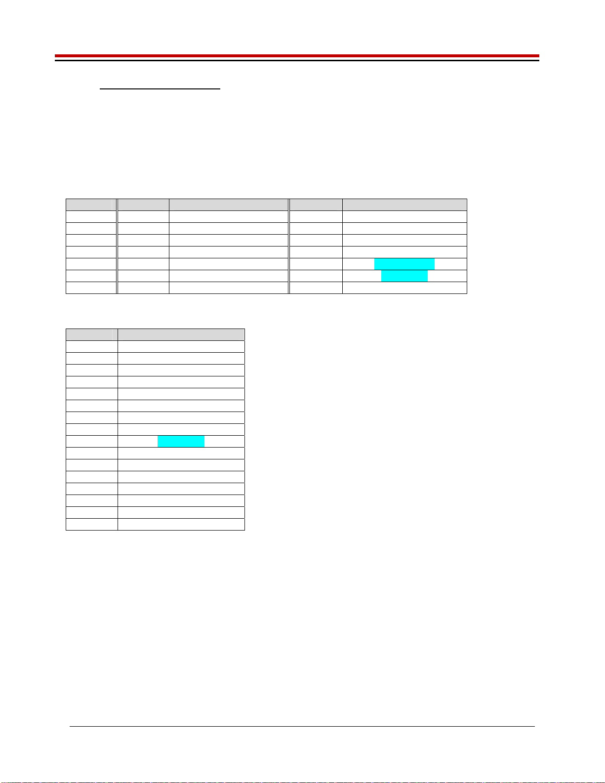
3.2 ADC and Analog Mux
The Octal FVMI contains a 24-bit ADC and analog muxes. Table 9 lists the Jupiter EVM loadboard
specific mux input sources. Table 10 lists the Jupiter EVM loadboard LB_AMUX analog mux which is
routed to the VINP13 and VINN8 nodes.
Note: Most signals go through channel protectors or voltage dividers (i.e. VCC) since they could exceed
FVMI Supplies (+20V/-15V).
Table 9: FVMI Analog Mux – VINPOS(A) & VINNEG(A) Mapping
Addr VINP# VINPOS(A) VINN# VINNEG(A)
7 VINP8 Reserved VINN8 VREF Div Sense
8 VINP9 GANG_MON(p) VINN9 TJ (Master)
9 VINP10 EXT_SENSE(p) VINN10 LB_AMUX (see below)
10 VINP11 MONITOR(p) VINN11 TJ (Slave)
11 VINP12 SENSE(p) VINN12 MON_REF(p)
12 VINP13 LB_AMUX (see below) VINN13 GANG3(p)
13 VINP14 TEST_NODE(p) VINN14 REXT
Table 10: Jupiter Loadboard Analog Mux Definitions - LB_AMUX Mapping
Addr Loadboard Amux
0 DUT_GND
1 VCCOUT_DIV
2 EXT_SENSE(p)
3 VCC_DIV
4 CAP_AP(p)
5 CAP_AN(p)
6 TN_DIV
7 CAP_SR(p)
8 GANG2(p)
9 CAP_BP(p)
10 EXT_FORCE(p)
11 VEE_DIV
12 CAP_BN(p)
13 RNET_SENSE
14 FORCE_A(p)
15 FORCE_B(p)
Note: Addr#8 was connected to SENSE(p) on the RevB loadboard. However, the software never used it.
Table of contents
Other ELEVATE Motherboard manuals


