3.6 High-Level Page...............................................................................................................................................................14
3.7 Diagnostic Page............................................................................................................................................................... 18
3.8 Eye Monitor Page.............................................................................................................................................................19
4 PCB Material Information.....................................................................................................................................................20
4.1 DS160PT801 PCB Design............................................................................................................................................... 20
4.2 DS160PT801 PCB Stackup............................................................................................................................................. 20
4.3 DS160PT801 PCB Power Distribution............................................................................................................................. 20
4.4 DS160PT801 Local Decoupling....................................................................................................................................... 22
5 DS160PT801X16EVM Schematic......................................................................................................................................... 24
6 Hardware BOM...................................................................................................................................................................... 33
7 Revision History................................................................................................................................................................... 39
List of Figures
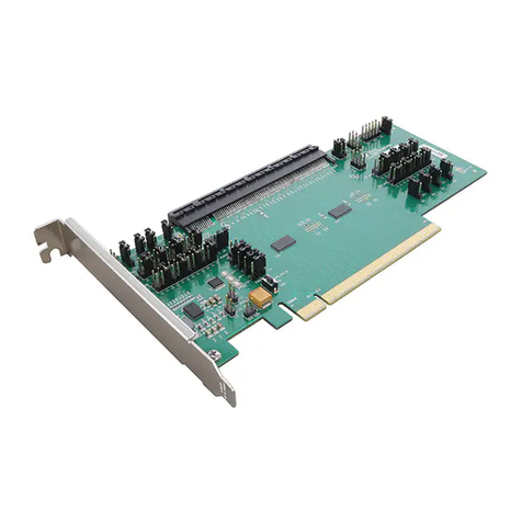
Figure 1-1. DS160PT801 EVM.................................................................................................................................................... 1
Figure 1-1. DS160PT801X16EVM EEPROM Control and Connection....................................................................................... 3
Figure 1-2. DS160PT801X16EVM SMBus Interface Connections.............................................................................................. 5
Figure 1-3. DS160PT801X16EVM PCIe PRSNT# Controls........................................................................................................ 5
Figure 1-4. Common Clock Topology Example........................................................................................................................... 6
Figure 1-5. Independent Clock Topology Example...................................................................................................................... 6
Figure 2-1. 1.17-V Power Supply Pin Controls............................................................................................................................ 7
Figure 2-2. DS160PT801X16EVM Power Network..................................................................................................................... 7
Figure 2-3. DS160PT801X16EVM Current Sense Measurement Locations............................................................................... 8
Figure 3-1. Configuration Page Screenshot.............................................................................................................................. 10
Figure 3-2. Low-Level Page Screenshot....................................................................................................................................11
Figure 3-3. EEPROM Page Screenshot.................................................................................................................................... 12
Figure 3-4. Control Panel Screenshot....................................................................................................................................... 13
Figure 3-5. High-Level Page Screenshot...................................................................................................................................14
Figure 3-6. High-Level Page – Device Status Screenshot........................................................................................................ 15
Figure 3-7. High Level Page – Device Status (Active Link) Screenshot....................................................................................16
Figure 3-8. High-Level – Rx EQ/DFE Page............................................................................................................................... 16
Figure 3-9. High-Level Page Tx FIR.......................................................................................................................................... 17
Figure 3-10. Diagnostic Page Screenshot................................................................................................................................. 18
Figure 3-11. Eye Monitor Page Screenshot...............................................................................................................................19
Figure 4-1. DS160PT801X16EVM PCB Stackup...................................................................................................................... 20
Figure 4-2. Layer 3 High-Speed Analog Analog Power Rails....................................................................................................21
Figure 4-3. Layer 4 Digital Power Rails..................................................................................................................................... 21
Figure 4-4. Layer 9 and 10 Power Distribution.......................................................................................................................... 22
Figure 4-5. Decoupling Solution Frequency Response............................................................................................................. 22
Figure 4-6. PCB Top Layer........................................................................................................................................................ 23
Figure 5-1. Schematic – Cover Sheet........................................................................................................................................24
Figure 5-2. Schematic – High Speed.........................................................................................................................................25
Figure 5-3. Schematic – Control................................................................................................................................................ 26
Figure 5-4. Schematic – Supply Voltage Regulators................................................................................................................. 27
Figure 5-5. Schematic – Retimer 1 Current Sense and Decoupling..........................................................................................28
Figure 5-6. Schematic – Retimer 0 Current Sense and Decoupling..........................................................................................29
Figure 5-7. Schematic – PCIe Gen4 Clock Generation............................................................................................................. 30
Figure 5-8. Schematic – PCIe Gen4 Clock Buffer..................................................................................................................... 31
Figure 5-9. Schematic – MSP430 Microcontroller..................................................................................................................... 32
List of Tables
Table 1-1. Default EVM Jumper Positions................................................................................................................................... 4
Table 6-1. DS160PT801X16EVM Bill of Materials.....................................................................................................................33
Trademarks
Windows® is a registered trademark of Microsoft Corporation.
All trademarks are the property of their respective owners.
Trademarks www.ti.com
2DS160PT801X16EVM Riser Card Evaluation Module SNLU254A – NOVEMBER 2020 – REVISED JULY 2022
Submit Document Feedback
Copyright © 2022 Texas Instruments Incorporated
