Elexa GUARDIAN GBR1 User manual

GBR1
User Manual
Guardian Bridge
BY ELEXA

Page 2
Guardian Bridge Advanced User Manual
Preface
BY ELEXA
As this is the full User Manual, a working knowledge of Z-Wave automa-
tion terminology and concepts will be assumed. If you are a beginner user,
please visit www.getguardian.com for instructions. This manual will pro-
vide in-depth technical information about the Guardian Bridge, especially
in regards to its compliance to the Z-Wave standard (such as compatible
Command Classes, Association Group capabilities, special features, and
other information) that will help you maximize the utility of this product in
your system.
Preface

Page 3
Guardian Bridge Advanced User Manual
Table of Contents
BY ELEXA
Table of Contents
Preface ........................................................................................................2
Description ..................................................................................................4
Specifications..............................................................................................4
Inclusion & Exclusion...................................................................................5
Reset to Factory Default ..............................................................................6
Physical Installation ....................................................................................7
LEDs Behavior .............................................................................................8
Button Behavior ...........................................................................................9
Compatible Command Classes..................................................................10
“Configuration” Command Class Parameters ............................................12
Troubleshooting ........................................................................................13
Warranty & Support....................................................................................14

Page 4
Guardian Bridge Advanced User Manual
Specications
BY ELEXA
Specications
Technical Specications
Radio protocol Z-Wave(500 series)
LoRa
Power supply 5 VDC OR 12VDC
Working current NA
Operating temperature 0 - 40 °C
Radio frequency 908.4 MHz US (Z-Wave)
915 MHz (LoRa)
Range Up to 40m (Z-Wave) depending on environment
Up to 500m (LoRa)
Dimensions (L x W) Board: 119 x 60 mm
Update OTA
Guardian Bridge device was developed to provide the Guardian
product line compatibility with Z-Wave Network protocol.
Description

Page 5
Guardian Bridge Advanced User Manual
Inclusion & Exclusion
BY ELEXA
Inclusion (Add to System) for Z-Wave and LoRa
1. For proper inclusion, bring the Guardian Bridge to the final location where it will
be used*.
2. Follow the instructions for your Z-Wave controller to enter on inclusion mode.
3. Supply power to the Guardian Bridge to begin inclusion mode. If the Guard-
ian Bridge is already powered on, press the button 3 times quickly within 1,5 se-
conds.
4. The device will enter inclusion mode for 15 seconds.
Upon successful inclusion, the 1st LED will stop blinking and stay turned off.
Exclusion (Remove from System) for Z-Wave and LoRa
Follow the instructions for your Z-Wave Certified Controller to enter exclusion
mode. When prompted by the controller:
1. Make sure the Guardian Bridge is powered on.
2. Press the Button 3 times quickly within 1,5 seconds.
Upon successful exclusion, the 1st LED will start blinking in 500ms.
NWI - Network Wide Inclusion
This Device supports NWI - Network Wide Inclusion.
1. Follow the instructions for your Z-Wave controller to enter on Inclusion/Exclu-
sion mode.
2. Supply power to the Guardian Bridge to begin inclusion/exclusion mode. If
the Guardian Bridge is already powered on, NWI will be activated automatically if
Guardian Bridge is already out of a Z-Wave Network.
3. When Guardian Bridge is out a Z-Wave Network, and Controller enters in Exclu-
sion mode, Guardian Bridge will be removed automatically through the NWI.
Upon successful in both cases, results is the same as Inclusion/Exclusion Default
procedures.
*For non Z-Wave Plus networks, please consult the owner’s manual for your primary controller to determine the best method/location
for adding the Guardian Bridge to your Z-Wave network. A Security Enabled Z-Wave Controller must be used in order to fully utilize the
product.
Inclusion & Exclusion

Page 6
Guardian Bridge Advanced User Manual
Reset to Factory Default
BY ELEXA
Resetting the Guardian Bridge
If needed, the Guardian Bridge can be reset locally by following these steps.
Only do this if your Z-Wave controller is missing or otherwise unreachable.
Beware that resetting your device will disconnect it from the system:
1. Make sure that your Guardian Bridge is powered on.
2. Press & Hold the button for 10 seconds.
3. The 1st LED will turn on and right after that, release the Button.
The Guardian Bridge memory will be erased to factory settings excluding
all Associations. This procedure also sends a Device Reset Locally to AG01
- Lifeline notification.
4. The 1st LED will start blinking in 500ms.
Reset to Factory Default

Page 7
Guardian Bridge Advanced User Manual
Physical Installation
BY ELEXA
The Guardian Bridge can be plugged directly into a Micro USB power supply.
Include the Guardian Bridge into your Z-Wave network and make sure it can
communicate from the installation location before continuing further.
Physical Installation

Page 8
Guardian Bridge Advanced User Manual
LEDs Behavior
BY ELEXA
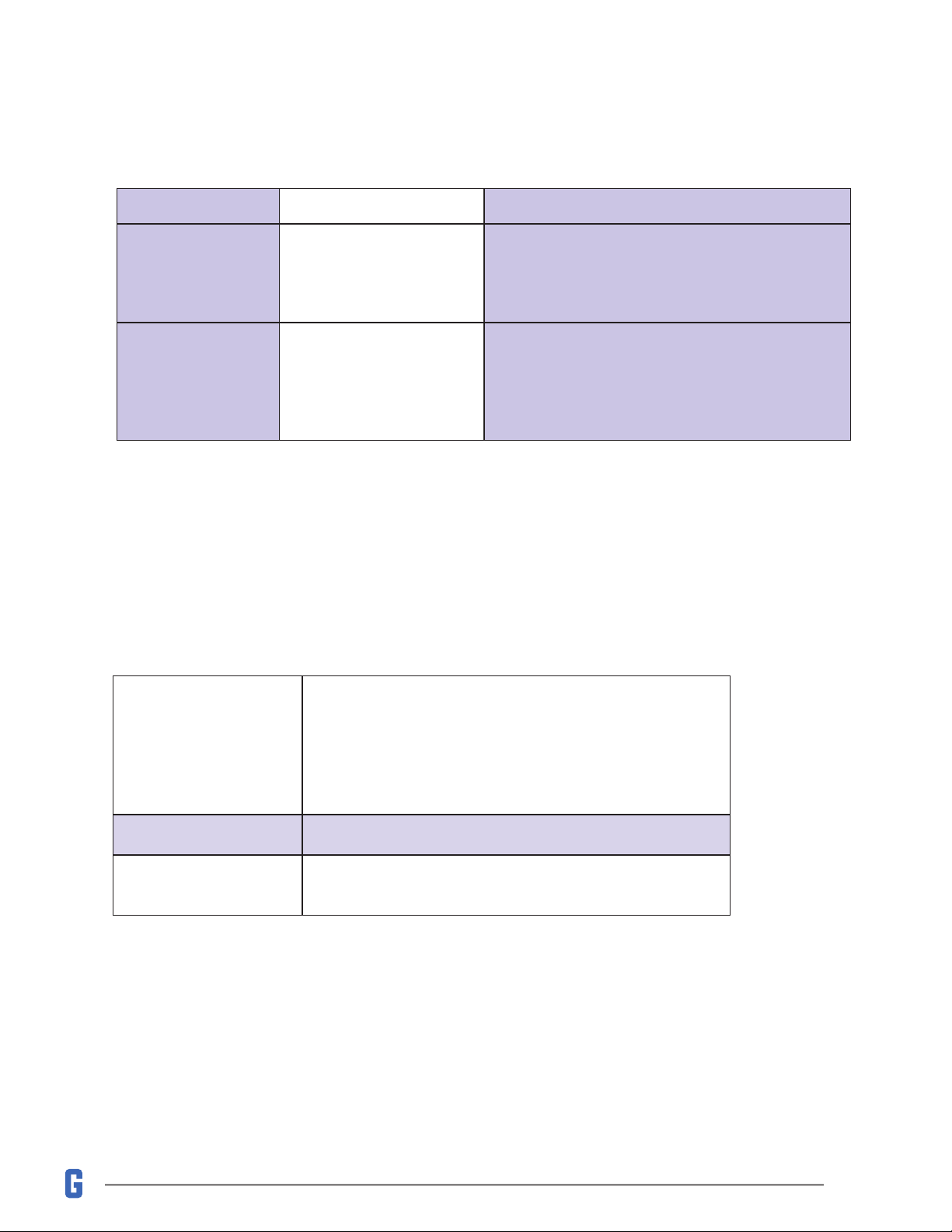
LED Behavior This happens when…
First LED (Z-Wave)
1st LED Blinking in 500ms Guardian Bridge isn’t in a Z-Wave Network
1st LED Turned Off Guardian Bridge is included in a Z-Wave
Network
1st LED Flash 1st LED will ash every time that a
Z-Wave transmission happens.
Second LED
(Power) LED is On Guardian Bridge is Powered On
Third LED
(Guardian RF) LED Flashes 3rd LED will ash every time that a
Guardian RF transmission happens.
LEDs Behavior
Page 9
Guardian Bridge Advanced User Manual
Button Behavior
BY ELEXA
LED Behavior This happens when…
First LED (Z-Wave)
1st LED Blinking in 500ms Guardian Bridge isn’t in a Z-Wave Network
1st LED Turned Off Guardian Bridge is included in a Z-Wave
Network
1st LED Flash 1st LED will ash every time that a
Z-Wave transmission happens.
Second LED
(Power) LED is On Guardian Bridge is Powered On
Third LED
(Guardian RF) LED Flashes 3rd LED will ash every time that a
Guardian RF transmission happens.
Action Condition Result
Push Button
3x within 1,5
seconds
Always Guardian Bridge will enter in Learn Mode
(Add/Remove from a Z-Wave Network)
Press and Hold
for 10 seconds Always
The Guardian Bridge memory will be erased to
factory settings excluding all Associations. This
procedure also sends a Device Reset Locally to
AG01 - Lifeline notication.
Association Groups (AGs)
The Guardian Bridge supports up to 5 Node IDs on AGs. Please see be-
low a description of all available Association Groups:
Association Group 01
Lifeline
This AG sends Binary Report when happens a Valve
Open/Close action.
It also supports a Device Reset Locally.
When any Guardian Leak Detector is wet, the Device
will send a Leak Notication
Association Group 02 This AG supports a Open/Close Basic Report
Association Group 03 This AG supports a Sensor Multilevel Report contain-
ing the Temperature information every 60 seconds
Button Behavior
Page 10
Guardian Bridge Advanced User Manual
Compatible Command Classes
BY ELEXA
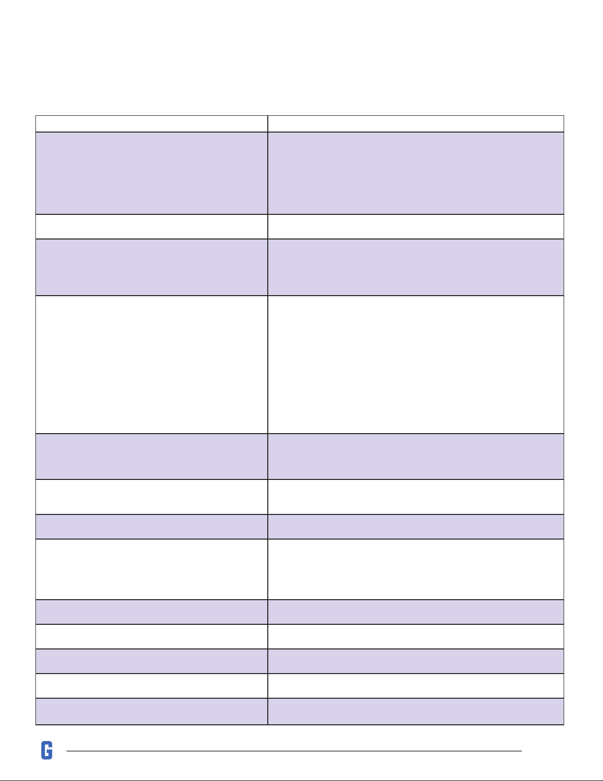
Command Class Notes
COMMAND_CLASS_VERSION V2 (86)
Returned Value: 03 04 3D 01 01 01 00
Z-Wave Library Type: 03
(Enhanced Slave)
Protocol Version: 04 3D
Protocol Sub-Version: 01 01
Application Version: 01
Application Sub-Version: 00
COMMAND_CLASS_BASIC V1 (20) -
COMMAND_CLASS_SWITCH_BINARY V1 (25)
Binary Switch commands will open/close the valve. Reports are used
to communicate valve opening/closing
Valve Open: FF
Valve Closed: 00
COMMAND_CLASS_SENSOR_MULTILEVEL V11 (31)
The Multilevel CC is used to communicate the temperature recorded
by the Valve Controller in the Guardian system. This is only reported
to association group 3.
Returned Value: 01 XX XX
Sensor Type 01 (Temperature)
Precision/Scale/Size (Celsius) 01 (Precision = 000; Scale = 00; Size =
001)
Precision/Scale/Size (Farenheit) 01 (Precision = 000; Scale = 00; Size
= 001)
Sensor Data 00 ~ FF (-125 ~ 125 in Degrees Fahrenheit or Celsius)
COMMAND_CLASS_MULTI_CHANNEL V4 (60)
The Multi Channel Command Class is used to distinguish commands
to/from the Valve Controller endpoint (endpoint 1) and the Leak De-
tector endpoint (endpoint 2).
COMMAND_CLASS_ASSOCIATION V2 (85) Group 1
Group 1 is the “Lifeline” group, which can hold ve devices.
COMMAND_CLASS_ASSOCIATION_GRP_INFO V3 (59) -
COMMAND_CLASS_MANUFACTURER_SPECIFIC V2
(72)
Returned Value: 02 1F 01 02 03 04
Manufacturer ID: 02 1F
Product Type: 01 02
Product ID: 03 04
COMMAND_CLASS_DEVICE_RESET_LOCALLY V1 (5A) -
COMMAND_CLASS_POWERLEVEL V1 (73) -
COMMAND_CLASS_SUPERVISION V1 (6C) -
COMMAND_CLASS_FIRMWARE_UPDATE_MD V4 (7A) -
COMMAND_CLASS_CONFIGURATION V1 (70) See ““Conguration” Command Class Parameters”
Compatible Command Classes
Page 11
Guardian Bridge Advanced User Manual
Compatible Command Classes
BY ELEXA
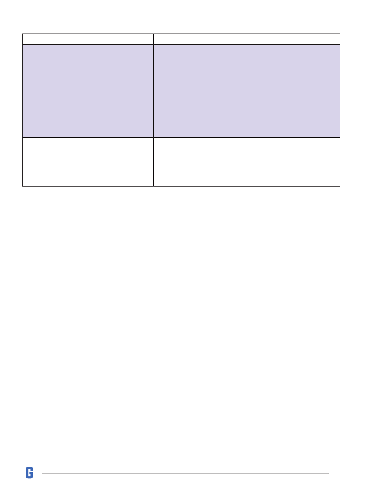
Command Class Notes
COMMAND_CLASS_NOTIFICATION V8 (71)
The Guardian Bridge sends a notication report to association group
1 when any Leak Detector in the system senses moisture.
Returned Value: 00 00 00 FF 05 XX 00 00
V1 Alarm Type 00 (Unsupported)
V1 Alarm Level 00 (Unsupported)
Notication Status FF (Unsolicited Reporting is Enabled)
Notication Type 05 (Water Alarm)
Leak Detected Event 02 (Water Leak Detected, Unknown Location)
Leak Removed Event 00 (Event Inactive)
Sequence/Reserved/Event Parameters Length 00
Notication Event Parameters 00 (No Event Parameters)
COMMAND_CLASS_ZWAVE_PLUS INFO V2 (5E)
Returned Value: 01 05 00 15 00 15 00
Z-Wave Plus Version: 01
Role Type: 05
Node Type: 00
Installer Icon Type: 15 00
User Icon Type: 15 00

Page 12
Guardian Bridge Advanced User Manual
“Conguration” Command Class Parameters
BY ELEXA
Configuration parameters are sent using a standard syntax to ensure interopera-
bility between all manufacturers’ products. All values are represented using the
hexadecimal number system.
Typical syntax is as shown below. Note that the value sent must be the exact size,
in bytes, as accepted by the setting. The “extra” spaces should be filled with zeros
(see the “value” column below.)
Example Configuration Parameter: 02 02 00 0A
Param # Size Value
02
(Param #2)
02
(2 Bytes)
00 0A
(10)
“Conguration” Command Class Parameters
Size Name Available Values
Default
Value
01
This parameter sets the Temperature scale. Is possible to choose between Celsius and
Farenheight.
01 Temperature Scale 00 - Farenheight
01- Celsius
00

Page 13
Guardian Bridge Advanced User Manual
Troubleshooting
BY ELEXA
:A Under Development
Troubleshooting

Page 14
Guardian Bridge Advanced User Manual
Warranty & Support
BY ELEXA
If you have questions, our trained Customer Service
Department is happy to assist you 24 hours a day, 7 days a
week. Contact Elexa Customer Service as follows: • In North
America dial: 1-855-249-1754 • Email Elexa at support@
getguardian.com
DO NOT RETURN THIS PRODUCT TO THE STORE OR
WEBSITE FROM WHICH IT WAS PURCHASED
If you believe the product is defective, has a missing or
broken part or are having difficulty with it please contact
Elexa as listed above for a quick and efficient solution to
the problem.
Legal Notices: This device complies with part 15 of the FCC
rules. Operation is subject to the following two conditions
(1) This device may not cause harmful interference, and (2)
this device must accept any interference received, including
interference that may cause undesired operation.
Note: This equipment has been tested and found to comply
with the limits for a Class B digital device, pursuant to part
15 of the FCC Rules. These limits are designed to provide
reasonable protection against harmful interference in a
residential installation. This equipment generates, uses
and can radiate radio frequency energy and, if not installed
and used in accordance with the instructions, may cause
harmful interference to radio communications.
However, there is no guarantee that interference will not
occur in a particular installation. If this equipment does
cause harmful interference to radio or television reception,
which can be determined by turning the equipment off and
on, the user is encouraged to try to correct the
Interference by one or more of the following measures:
Reorient or relocate the receiving antenna; increase the
separation between the equipment and the receiver; connect
the equipment into an outlet on a circuit different from that
to which the receiver is connected. Consult the dealer or an
experienced radio/TV technician for help.
This device complies with Industry Canada license-exempt
RSS standard(s). Operation is subject to the following two
conditions: (1) this device may not cause interference,
and (2) this device must accept any interference, including
interference that may cause undesired operation of the
device.
Elexa Consumer Products, Inc. (”ECP”) warrants to the
original retail purchaser (”Purchaser”) that the Guardian
Bridge (the “Product”) will be free of defects in materials or
workmanship under use for one (1) year from the date of
purchase (the “Warranty period”).
For the Purchaser only, if the Product fails to perform as
specified during the Warranty Period due to defective parts or
faulty workmanship, ECP will repair or replace the defective
or damaged parts of the Product. Normal wear and tear
is not covered nor is abnormal use, misuse, mishandling,
faulty installation, improper shipping, damage caused by
disasters such as fire, flood or earthquake, neglect, accident
or tampering. This warranty covers only normal use in the
United States or Canada.
To obtain warranty service during the Warranty Period,
call Elexa Customer Service (1-855-249-1754) or email:
damaged parts and documentation for a Return Material
Authorization (RMA). Products returned to ECP for repair
or replacement without authorization will be returned at the
sender’s expense. All warranty claims must be accompanied
by a legible copy of the original receipt showing date and
details of purchase. The RMA number must be clearly
written on the side of the shipping container in which you
return the Product or defective parts. Unless otherwise
instructed by ECP, the Product must be sent freight pre-paid
to the following address:
Elexa Consumer Products, c/o Promac,
1153 Timber Dr., Elgin, IL 60123
ECP will repair or replace the defective parts and return them
at ECP’s cost by a shipping method selected by ECP. When
contacting ECP to obtain an RMA, Purchaser may request
expedited return shipping at Purchaser’s expense.
THIS WARRANTY IS NOT TRANSFERABLE, AND, TO THE
MAXIMUM EXTENT PERMITTED BY APPLICABLE LAW IS
IN LIEU OF ALL OTHER WARRANTIES, REPRESENTATIONS
AND CONDITIONS, EXPRESSED OR IMPLIED, STATUTORY
OR OTHERWISE, INCLUDING BUT NOT LIMITED TO THE
IMPLIED WARRANTIES OF MERCHANTABILITY AND
FITNESS FOR A PARTICULAR PURPOSE. NO OTHER PERSON
OR REPRESENTATIVE IS AUTHORIZED TO MAKE ANY OTHER
WARRANTY ON BEHALF OF ECP OR ASSUME FOR ECP ANY
OTHER LIABILITY IN CONNECTION WITH THE SALE OF THIS
PRODUCT. IN NO EVENT WILL ECP BE LIABLE FOR ANY
DAMAGES, INCLUDING BUT NOT LIMITED TO INCIDENTAL,
SPECIAL OR CONSEQUENTIAL DAMAGES ARISING OUT OF
THE USE OR INABILITY TO USE THE PRODUCT, INCLUDING
DAMAGES DUE TO ECP’S NEGLIGENCE.
THIS WARRANTY GIVES YOU SPECIFIC LEGAL RIGHTS, AND
YOU MAY ALSO HAVE OTHER RIGHTS WHICH VARY FROM
STATE TO STATE AND COUNTRY TO COUNTRY.
This marking on the product, accessories or literature
indicates that the product and its electronic accessories
should not be disposed of with other household waste.
To prevent possible harm to the environment or human
health from uncontrolled waste disposal, please separate
these items from other types of waste and recycle them
responsibly to promote the sustainable reuse of material
resources.
Household users should contact either the retailer where
they purchased this product, or their government office, for
details of where and how they can take these items for
Environmentally safe recycling.
Business users should contact their supplier and check the
terms and conditions of the purchase contract. This product
and its electronic accessories should not be mixed with
other wastes for disposal.
This marking on the battery, manual or packaging indicates
that the batteries in this product should not be disposed of
with other household waste. Where marked, the chemical
symbols Hg, Cd or Pb indicate that the battery contains
mercury, cadmium or lead above the reference levels in EC
Directive 2006/66. If batteries are not properly disposed of,
these substances can cause harm to human health or the
environment.
Warranty & Support
Table of contents


