manuals.online logo
Brands
  1. Home
  2. •
  3. Brands
  4. •
  5. Status Instruments
  6. •
  7. Transmitter
  8. •
  9. Status Instruments SEM710 User manual

Status Instruments SEM710 User manual

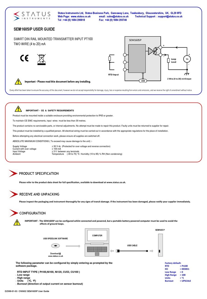
IMPORTANT- CE & SAFETYREQUIREMENTS
ProductmustbeDINrailmounted,insideasuitableenclosureprovidingenvironmentalprotectiontoIP65orgreater.
TomaintainCEEMCrequirements,input wires mustbelessthan30meters.
Theproductcontainsnoserviceableparts,orinternaladjustments.noattemptmustbemadetorepairthisproduct.Faultyunitsmustbereturnedto
supplierforrepair.
Thisproductmustbeinstalledbyaqualifiedperson.Allelectricalwiringmustbecarriedoutinaccordancewiththeappropriateregulationsforthe
placeofinstallation.
Beforeattemptinganyelectricalconnectionwork,pleaseensureallsuppliesareswitchedoff.
ABSOLUTEMAXIMUMOPERATINGCONDITIONS(Toexceedmaycausedamagetotheunit):-
SupplyVoltage ±30VDC (Protectedforovervoltageandreverseconnection)
Currentwithovervoltage ±200mA
InputVoltage ±5V betweenanyterminals
InputCurrent ±100mAbetweenterminals7&10
Ambient Temperature(-30to75)°C Humidity(10to95)%RH(Noncondensing)
SEM710 USER GUIDE
HEAD MOUNTED TRANSMITTER
UNIVERSAL TEMPERATURE INPUT
TWO WIRE (4 to 20) mA OUTPUT WITH
DISPLAY
Every effort has been taken to ensure the accuracy of this document, however we do not accept responsibility for damage, injury, loss or expense resulting from errors and omissions, and we reserve the right of amendment without notice.
Important - Please read this document before installing.
PRODUCT SPECIFICATION
RECEIVE AND UNPACKING
CONFIGURATION
SEM710
M-CONFIG SOFTWARE
USB CABLE
Disk or download @
www.statinst.com
COMPUTER
The following parameter can be configured by simply entering as prompted by the software
package.
· Input type (K, J, E, N, T, R, S, Pt100)
· Low range
· High range
· Units (°C, °F)
· Burnout (direction of output current on sensor burnout)
· User Trim (ON / OFF) [option to lock out trim function]
Display mode Input (°C / °F) or Output mA
Factory default:
Input type = P
Low Range = 0
High Range = 100
Units = °C
Burnout = UPSCALE
User Trim = ON
Display = °C
Input
3
2
1
+
-
PT100
2 Wire (4-20) mA Output
SEM710
+
-V
s
Loop
Load
US
B
+
-
100.0
IMPORTANTTheSEM710canbeconfiguredwhileconnectedandpowered,but aportablebatterypoweredcomputermustbeusedtoavoidtheeffects
ofgroundloops.
-
Status Instruments Inc, PO Box 548, 456 Park Avenue, Scotch Plains, NJ 07076
Web Page: www.statinst.com Tel: (800) 700-3272 Fax: (800) 700-5468 email: [email protected]
Pleaserefertotheproductdatasheetforfullspecification,availabletodownloadatwww.statinst.com.
Pleaseinspectthepackagingandinstrumentthoroughlyforanysignsoftransitdamage.Iftheinstrumenthasbeendamaged,pleasenotifyyoursupplierimmediately.
SEM710_User_GuideUSA_5_09
USER TRIM
Power Supply (24VDC)
Input Simulator
User trim function allows manual adjustment of the output current, this
is useful for minor calibration adjustment or trimming out any sensor
error, ± 5% of range adjustment is available at both offset and span.
Raise and lower buttons are provided on the back, of the transmitter,
accessed using a 3 mm flat blade screw driver. Insert the screw driver
into the appropriate slot to operate the button. The button has a click
action.
METHOD
1.0 Ensure the SEM710 is correctly configured. Connect transmitter to
a suitable input simulator or sensor. Connect output to a 24V dc
supply. Turn supply on, set input to either offset or span calibration
point.
2.0 During normal operation the SEM710 Display reading is calculated
from the output current drive not directly from the input, therefore the
display may be used to monitor trim adjustment. If required the output
current may also be monitored with a current meter.
3.0 If the input falls outside the ranged output the SEM710 will enter
burnout condition on the output, but will continue to display the
temperature. The SEM710 will indicate this by alternating the display
to show 'OuER' or 'uND' depending on the burnout direction of the
input reading.
4.0 Trim output current by pressing either the raise or lower button,
single click to step advance , or press continuously to auto advance.
The SEM710 unit will automatically detect the correct trim point.
+
-
+
-
SEM710
The transmitter will auto-
matically detect the correct
trim point (offset or span)
based on the output current
drive. Offset will be trimmed
when the current is be-
tween (3.8 to 6) mA, span
when the current is between
(18 to 22) mA. No trim
action occurs at any other
current.
offset
span
3.8 6 18 22
mA
or Sensor
SUPPLY (Vs) = (11 to 30) VDC
MAX LOAD Ohms = (Vs - 11) / 0.021
OUTPUT
2 Wire (4-20) mA
Max cable length 1000 meters
Use twisted pair cable > 30 meters
+
-
Pt100
Ø 3 mm
ELECTRICAL INSTALLATION
Screw Driver
Shielded Cable
TC Compensation Cable
Shielded
TURN OFF SUPPLY BEFORE WORKING ON ANY ELECTRICAL CONNECTION
T/C Vs
Loop
Load
USB
+
-
3
2
1
+
-
Twisted Pair
100.0
SEM710
+
Pt100
DISPLAY
DISPLAY ERROR MESSAGES
ERR u Sensor or system error
. (dec. pt. ) u Configuration powered by USB
OuER (over 105.0) u Output over range (flashes actual
I/P measurement then Error Message)
uND (under -0.5) u Output under range (flashes actual
I/P measurement then Error Message)
USB
LOWER
RAISE
+
3
2
1
-
_
INPUT CONNECTION
For cable lengths < 3 Meters shielded or twisted pair is not
required.
For cable length > 3 Meters and < 30 Meters shielded or
twisted pair is required.
Cable lengths > 30 Meters are not recommended.
Pt 100 Inputs of all three wires must be equal length
(resistance).
T/C Inputs must use the correct compensation cable.
T/C
MECHANICAL INSTALLATION
SEM710_User_GuideUSA_5_09
+
-
Pt100
T/C 3
2
1
-
Trimming The Output Of An SEM710 Indicating Temperature Transmitter
A –In order to setup the SEM710 connect a USB
port on your computer to the USB port on the
SEM710 using a USB type-A / Mini USB 4-pin
cable. Start the Status Instruments USB LINK
Software and setup the temperature range that
you want the 4 to 20mA output to be. Also
make sure the TRIM feature is turned on.
Back of SEM710 Indicating Transmitter
B -In order to TRIM the output of an SEM710 Indicating Temperature Transmitter you must use a
temperature sensor simulator and do the following:
1. Connect your temperature sensor output from your temperature sensor simulator to terminals
1, 2, & 3 as soon below for a thermocouple or an RTD:
Thermocouple:
Connect positive lead to terminal 1.
Connect negative lead to terminal 2.
RTD:
Connect two same color leads to terminals 1 & 2.
Connect odd colored lead to terminal 3.
2. Connect the power leads from your temperature sensor simulator to the “+” and “—“ terminals
shown on the above drawing.
3. Enter the “TRIM” mode of the SEM710 Transmitter by holding down the “RAISE” button for
more than 2 seconds (when in the trim mode the “C” or “F” LED on the front of the unit will
flash).
4. Now set the temperature equivalent of the 4mA output on the transmitter and read the output
current on your sensor simulator. If it is above 4mA press the “LOWER” button until it is at 4mA,
if it is below 4mA press the “RAISE” button until it is at 4mA (you can also read the low
temperature of the output range on the transmitter indicator on the front of the transmitter).
5. Next set the temperature equivalent of the 20mA output on the transmitter and read the output
current on your sensor simulator. If it is above 20mA press the “LOWER” button until it is at
20mA, if it is below 20mA press the “RAISE” button until it is at 20mA (you can also read the high
temperature of the output range on the transmitter indicator on the front of the transmitter).
6. Once the TRIM is complete allow 30 seconds with no button presses for the transmitter to store
the settings and return to normal operation.
USB
LOWER
RAISE
+
3
2
1
_

Other Status Instruments Transmitter manuals

Status Instruments SEM1605/P User manual

Status Instruments

Status Instruments SEM1605/P User manual

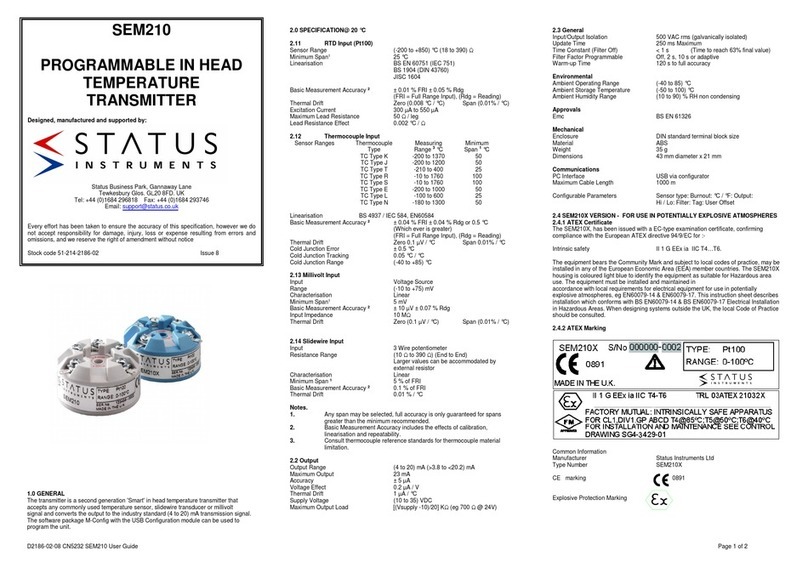
Status Instruments SEM210 User manual

Status Instruments

Status Instruments SEM210 User manual

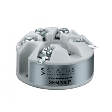
Status Instruments SEM206/P User manual

Status Instruments

Status Instruments SEM206/P User manual

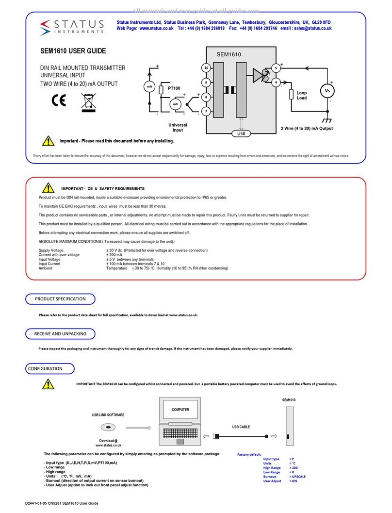
Status Instruments SEM1610 User manual

Status Instruments

Status Instruments SEM1610 User manual

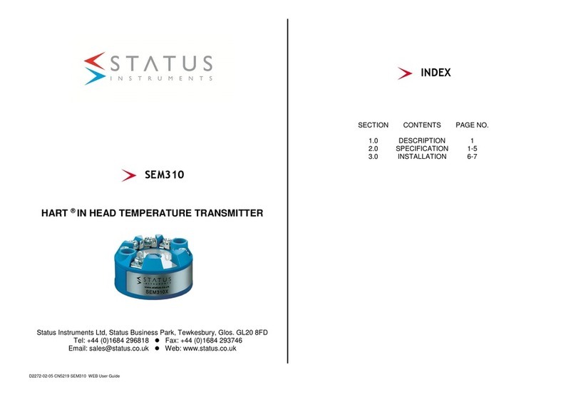
Status Instruments SEM310 User manual

Status Instruments

Status Instruments SEM310 User manual

Status Instruments SEM203P MKII User manual

Status Instruments

Status Instruments SEM203P MKII User manual

Status Instruments SEM210X Installation instructions

Status Instruments

Status Instruments SEM210X Installation instructions

Status Instruments SEM203/TC User manual

Status Instruments

Status Instruments SEM203/TC User manual

Status Instruments SEM1610 User manual

Status Instruments

Status Instruments SEM1610 User manual

Status Instruments SEM110 User manual

Status Instruments

Status Instruments SEM110 User manual

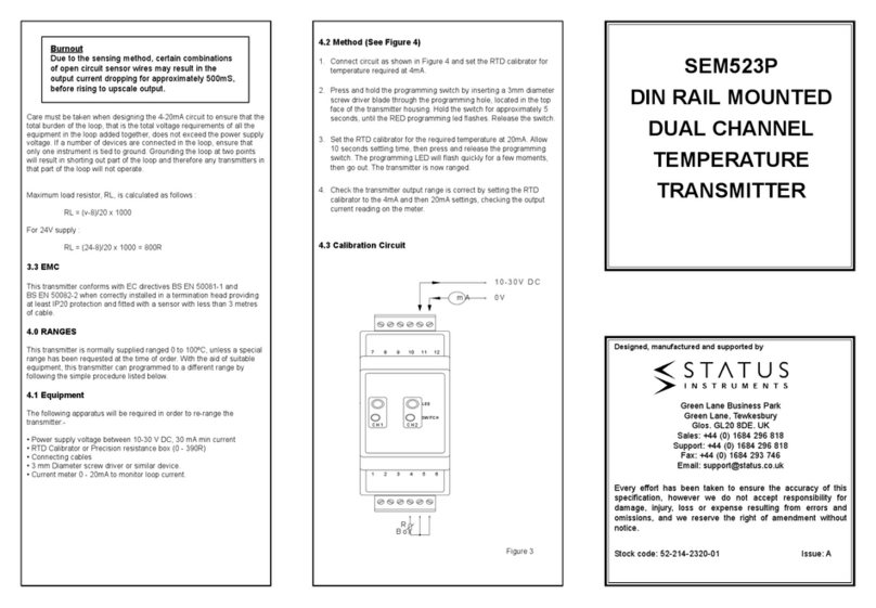
Status Instruments SEM523P User manual

Status Instruments

Status Instruments SEM523P User manual

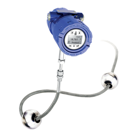
Status Instruments WTX700 Series User manual

Status Instruments

Status Instruments WTX700 Series User manual

Status Instruments SEM310 User manual

Status Instruments

Status Instruments SEM310 User manual

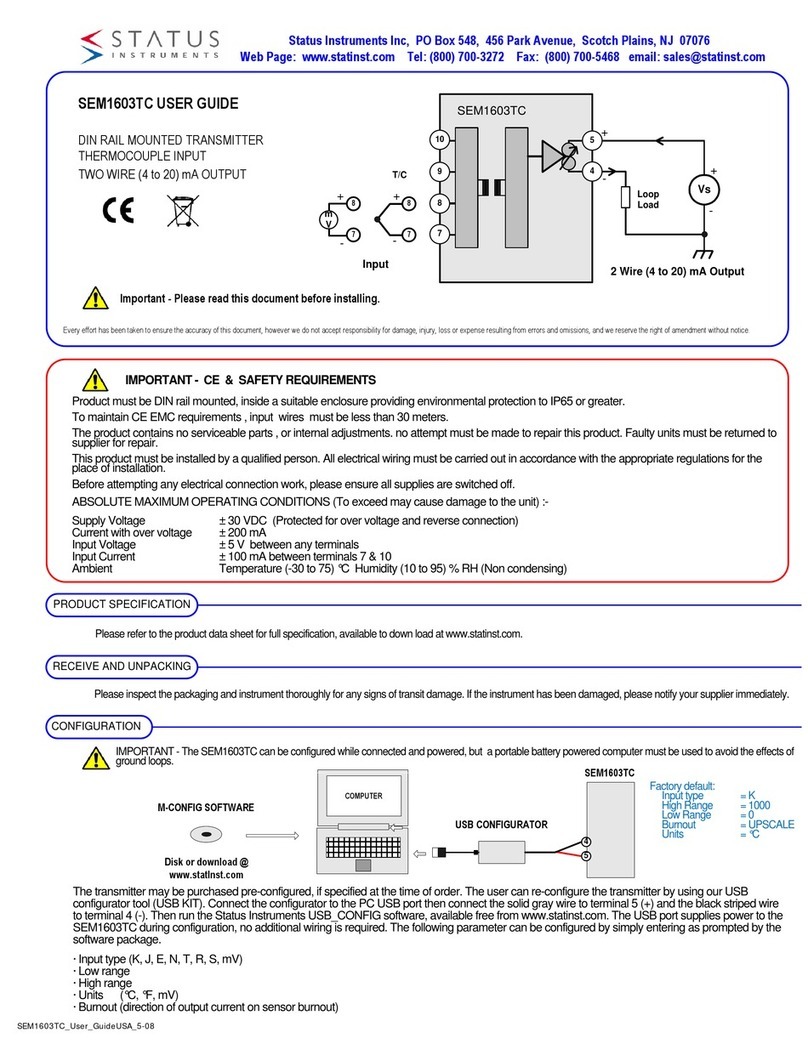
Status Instruments SEM1603TC User manual

Status Instruments

Status Instruments SEM1603TC User manual

Popular Transmitter manuals by other brands

JTS IN-64TH instruction manual

JTS

JTS IN-64TH instruction manual

MTS Systems LevelLimit Level Plus Operation manual

MTS Systems

MTS Systems LevelLimit Level Plus Operation manual

Williams Sound Hearing Helper T800 Manual and user guide

Williams Sound

Williams Sound Hearing Helper T800 Manual and user guide

Jula MarQuant 924-830 User instructions

Jula

Jula MarQuant 924-830 User instructions

NIVELCO NIPRESS DRD-6 Series user manual

NIVELCO

NIVELCO NIPRESS DRD-6 Series user manual

Anywave TRN-U1D quick start guide

Anywave

Anywave TRN-U1D quick start guide

Audiovox S1BTXA Programming guide

Audiovox

Audiovox S1BTXA Programming guide

Salcom 20-62 product manual

Salcom

Salcom 20-62 product manual

Endress+Hauser HART iTEMP TMT142B operating instructions

Endress+Hauser

Endress+Hauser HART iTEMP TMT142B operating instructions

Turbines FIC712-2 Installation and operation manual

Turbines

Turbines FIC712-2 Installation and operation manual

Cooper Security Scantronic 735r manual

Cooper Security

Cooper Security Scantronic 735r manual

Hampshire Controls TT Series operating instructions

Hampshire Controls

Hampshire Controls TT Series operating instructions

BWI Eagle AIR-EAGLE FM2 43-1000N4W-120VAC Product information bulletin

BWI Eagle

BWI Eagle AIR-EAGLE FM2 43-1000N4W-120VAC Product information bulletin

Siemens SITRANS L Series operating instructions

Siemens

Siemens SITRANS L Series operating instructions

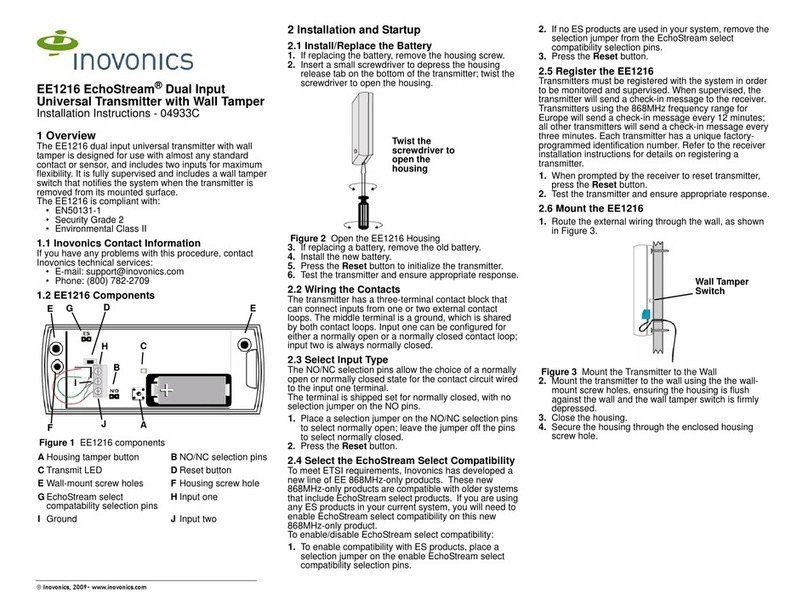
Inovonics EE1216 installation instructions

Inovonics

Inovonics EE1216 installation instructions

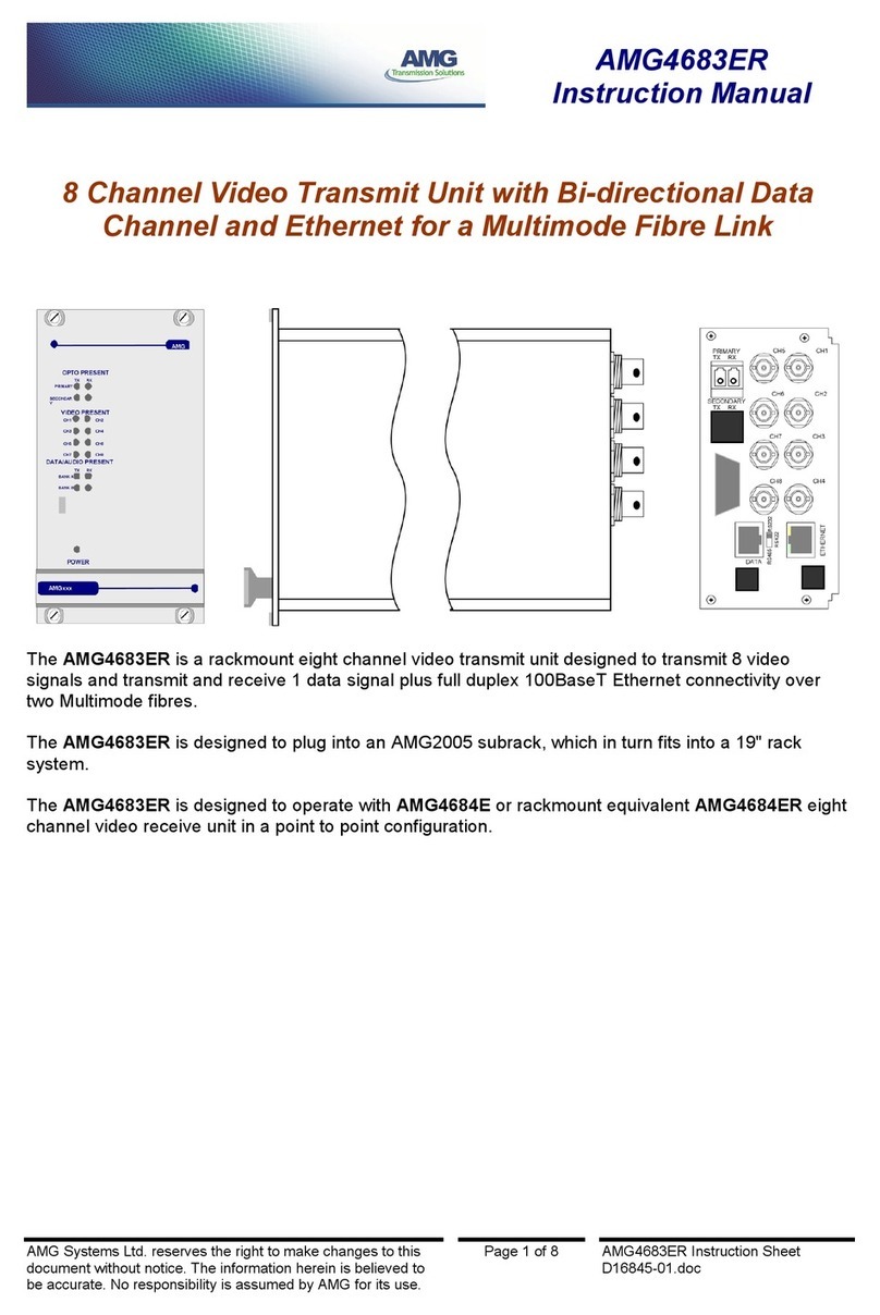
AMG AMG4683ER instruction manual

AMG

AMG AMG4683ER instruction manual

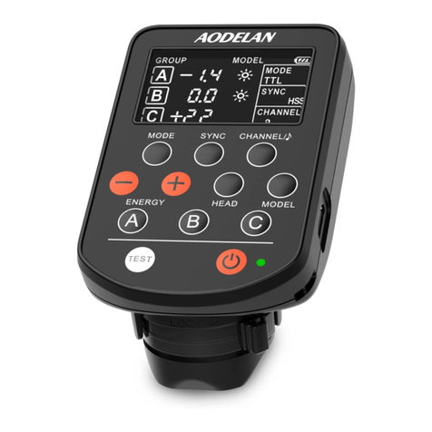
AODELAN E4 user manual

AODELAN

AODELAN E4 user manual

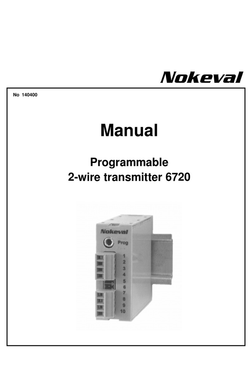
Nokeval 6720 manual

Nokeval

Nokeval 6720 manual

manuals.online logo
manuals.online logoBrands
  • About & Mission
  • Contact us
  • Privacy Policy
  • Terms and Conditions

Copyright 2025 Manuals.Online. All Rights Reserved.